Electronic Gear Hobbing was discussed during yesterdays’ Zoom meeting of the Society of Model and Experiment Engineers Digital Group.
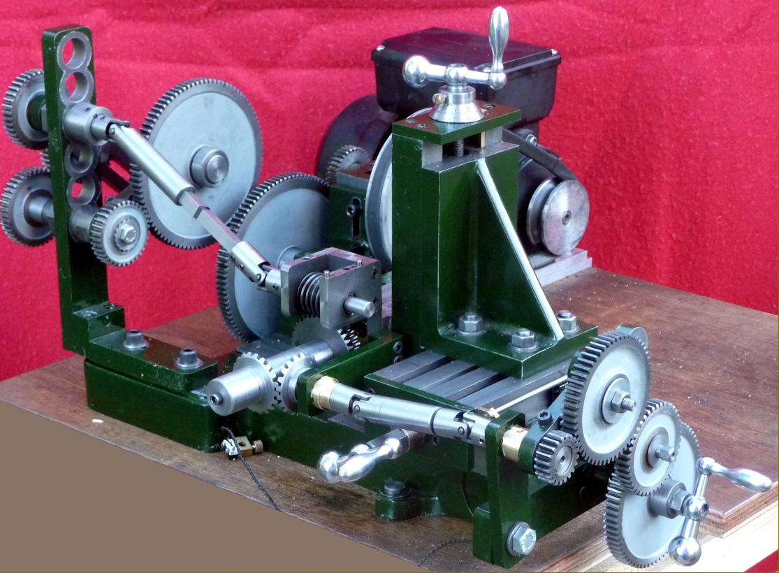
Gear Hobbing is more challenging than an Electronic Lead Screw; as I understand it an ELS only needs to create a single gear ratio whilst a hobber needs two or more. Example picture is of the Jacobe Gear Hobber described on the most excellent lathes.co.uk, loads of gears!
In a digital ELS a computer or conventional logic circuit, measures the lathe’s spindle speed, does a simple calculation, and sends a stream of pulses to a stepper or servo motor driving the lead-screw. Thus the lead-screw can be turned at any reasonable ratio relative to the spindle, and the electronics replace the change gears. There are a bunch of gotchas, notably the lead-screw and spindle have to stay in sync requiring the spindle speed to be measured accurately, and the electronics and lead-screw motor fast enough to keep up.
The advantage of a computer is that complex logic can be programmed and altered, which is generally quicker and easier than building the equivalent circuit from discrete components, which in turn is quicker and easier to develop than a complex mechanical design. But computers are slower than hard wired circuits, and electronic solutions introduce new problems: unlike a mechanical gear train they don’t stay in sync automatically.
The question was asked: which microcontroller is most suitable for this application? The group assumed that calculating speed would be the limitation, along with accumulating error due to calculating in floating point. Avoiding these problems implies a fast microcontroller, with high precision floating point executed on a built in Floating Point Accelerator (FPA). That eliminates most of the Arduino range, but the Nucleo is a possibility. Clough42’s successful ELS, uses a fast 32bit Texas Instruments microcontroller, which is less well known, at least to me!
Last night I looked at Clough42’s code and the Texas Instruments data-sheet:
The maths is short and sweet. Clough42’s code allows it to be done it either floating point or integer maths, I guess because integer will work on a cheaper TI microcontroller that doesn’t have a FPA. Anyway, the maths makes no provision for accumulating error, and is so short it can’t be a significant bottle-neck.
The TI microcontroller is designed for this type of application. In an ELS, the lathe spindle turns a rotary encoder, probably emitting 400 pulses per rotation, so the computer has to track over 13000 events per second at 2000rpm. An Arduino struggles with this because each pulse triggers an interrupt function that keeps track of position, speed and direction. The function is time-critical and uses a lot of processor time – a massive bottleneck. The TI controller avoids this bottleneck by continually decoding up to two rotary encoders in hardware: position, speed and direction do not have to be tracked by the processor, the information is read when needed. Much simpler and faster.
The TI microcontroller (F280049C) is a 100MHz 32-bit specialist that leaves an 8bit 16MHz in the dust for this requirement. That it only supports two rotary encoders in hardware may be a problem for an Electronic Gear Hobber, though it could support more in software in the same way as an Arduino.
Some Nucleo boards also appear to have a hardware rotary decoder, but I wasn’t able to find any details last night. Might be hard to use because the mbed development environment doesn’t support the hardware directly, and low-level programming is hard work.
So, the TI chip is now the most suitable that I know of for an Electronic Gear Hobber, but I don’t understand how many spindles it needs to measure, how many ratios and motors are needed, or how fast the computer needs to go. Anyone able to give a steer on that?
The Digital Group also discussed the advantages of a hardware solution based on phase locked oscillators. I understand the principle well enough to know the approach is feasible, but it’s outside my skill-set. Another technology I’m interested in, but mostly ignorant!
Surely an encoder based system would be more feasible for an electronic gear hobber. Constantly monitoring the rotation of the hob and knowing its position will allow you to calculate the correct required position for the gear blank at any point. This is the principle used in some electronic leadscrews so should be a good starting point for this. I think Clough42 did demonstrate this with his set up at some point. As the chuck was rotated by hand the carriage moved backwards or forwards to stay aligned with the thread groove.
The picture of the Jacobs looks a little different from normal I think. The bracket on the left is a bit more elaborate than normal but still could add the differential needed for prime gears.
Interesting that you mention PLLs in your last paragraph. As I was reading I was thinking of the similarity with digital PLLs for which (40 years ago) we had a dedicated chip using a “swallow counter” to correct the errors every few cycles. Errors were important as it was multiplied up to 18GHz and the correction glitches in the waveform added background noise.
Did you mention to the group the threads on here (unless it was the HSM forum) started by John Stevenson. He started with a 2000 slot encoder and a doubler to 4000 (might have been binary equivalent) so that it worked with a hardware binary divider chip. The high count might have been because of the 40:1 worm drive.
Later he reported that someone had made him a processor based solution but never gave details of the software writer or implementation.
I have hobbed gears using an optical encoder (Avago, 1000 cycles per rev) on the hob shaft and a “Syncron” elctronics unit supplied by Richard Bartlett of Coventry. Signal from the electronics activates a NEMA 23 stepper motor and drive package which drives the workholding Shaft via a 5:1 gear reduction. I only vaguely understand what’s going on in the electrics/electronics but, thanks to the information made available by Richard Bartlett and John Pace (article in MEW 193), it all works as it should and I have successfully cut several gears. My input has been to design and make the direct drive encoder mounting and the stepper motor / workholding shaft unit which, as it happens, is a modification of my Compact Dividing Head recently featured in MEW. My main difficulty in hobbing gears has been in loosing synchronisation between work and hob when power needs to be shut off for example to measure progress.
I would be interested to hear SOD’s comments on this set-up. As far as I can tell only one encoder and one stepper motor drive are involved.
One of the assumptions here (and, to avoid any misunderstandings, I was one of the participants in yesterday’s online discussion) is that the traditional gear hobber approach is taken. That is, the cutter spindle is motor-driven and then geared to rotate the gear being cut. However, if one were starting from scratch, one could tear up some aspects of the existing (e.g. Jacobs) approach and use the microcontroller to drive both cutter spindle and workpiece spindle. No encoder needed as the controller knows the exact position of both spindles at all times. Maybe servo (as is used for quite a few CNC lathes and mills, for example, so it’s familiar technology) or maybe a stepper would be enough. My choice is smallish servo, but that’s without serious analysis – just gut feel. Easy enough to accelerate both spindles synchronously when starting up. If the cutter spindle is not under direct control, then its speed needs to ramp up at a rate that the workpiece spindle can follow it – although the workpiece speeds are low enough here that I doubt that it matters too much. ELS systems seem to manage adequately.
Biggest issue seems to be avoiding cumulative errors when cutting awkward numbers. If the number of teeth on the gear is not a factor of the number of steps (or microsteps) available from its spindle driver then there will be approximations involved. This is where the Bressingham or similar algorithm comes in. Again, not breaking new ground here.
One aspect that was not discussed yesterday is that a third axis is also needed so that the cut, so to speak, moves across the face of the gear. Easy enough to do with a microcontroller – step across once per workpiece revolution. Not sure how the Jacobs handles that – is that the job of one of the handles in the image above? Then maybe add depth of cut on an additional axis, unless cutting full depth in one pass?
Your remark re. cumulative errors is a bit worrying as I don’t know the detail of how Richard Bartlett tackled it in my Syncron unit. I just assumed it wasn’t a problem so are you saying that there is no known system where it isn’t ? I haven’t noticed anything like this in the gears I have cut but they have all been with rather small numbers of teeth. By the way personally it is all new ground so I’ll be investigating Bressingham and Bresenham et al. as soon as I have finished here.
Regarding your third axis remark, in my case I feed along the x axis by hand. If the head of a vertical miller (which is what I use) carrying the hob is inclined at the hob helix angle there is no linking between the x feed and hob rotation – or perhaps I haven’t grasped your point.
There are ways of using integer arithmetic but not getting a cumulative error. Frances mentions Bressenham’s. Floating point is asking for trouble, a stepper motor is an integer device
Chris – if you haven’t noticed any problems, maybe there aren’t any! There are, perhaps, two things that mitigate against errors. One is a high step count per workpiece rev. For example, a typical stepper motor using 8x microstepping gives an effective step count per rev of 1600. The situation becomes even better when you are driving through a dividing head with, say, a 60:1 ratio. The problem is exactly similar to using a dividing head in the usual manual fashion – only certain tooth counts are possible. With direct indexing, you can only cut tooth counts which match the number of holes in the index plate but the worm and wheel in a dividing multiplies the available tooth counts considerably. When hobbing, you actually want finer movement than tooth-by-tooth, of course, as the ideal case is continuous movement. However, exact positioning still implies an integral number of “steps” per tooth.
However, using simple if unrealistic numbers to make the arithmetic easier, consider a system that can only manage 200 steps per workpiece rev. 40T, 50T, and a number of others can be cut with an exact number of steps. But what about 30T? Each tooth needs 200/30 = 6.666 steps – which is not possible. So, we cut the first tooth, advance by as close as we can get to 6.666 steps which is 7, and take the next cut. However, if we advance another 7 steps for the next cut, we shall be at 14 steps from the start rather than the “best estimate” of 2×6.666 = 13.333, rounding to 13. Ideally, we then advance 7 steps to give 20 from the start, which is exact. The Bressenham algorithm addresses the way in which we can calculate the best integer estimate to an exact decimal number. In practice, it’s all a bit more complicated as for hobbing, we are looking at an approximation to continuous motion but at heart, it’s the same problem.
As for advancing for each cut – my feeling was that if you were starting from scratch, you might as well motorise the X axis as well; the software extension to drive it is pretty trivial. It’s the equivalent of the electronic leadscrew moving only the saddle while depth of cut is put on manually. A CNC lathe automates both motions.
In the case of encoders you can make use of index pulses to ensure you start each rotation at the correct point. If there is an encoder on the hob shaft and an encoder on the blank shaft you can reset each rotation of the blank to the same start point each time. If needed you could retract the hob from the workpiece after each rotation of the blank and re-home both to the index pulse before commencing another pass.
Thanks for that. The danger is that once the power has been turned off the hob shaft could be accidently moved. Less so with the stepper motor because of the cogging due to magnetic effect. What you suggest would be ideal although the associated electronics would be challenging for an electronics ignoramus such as myself. For instance does the homing imply the ability control power to both the hob shaft and stepper from a centre control ? If so this would need quite a tear up of the current arrangement of variable speed hob and independant stepper drive. For now anyway I’ll just have to be very careful.
Thanks for that. The danger is that once the power has been turned off the hob shaft could be accidently moved.
If you use servo motors, equipped with absolute encoders, you can switch off the power, rotate any axis in any direction and position them in exactly the same place when powered on. These kind of servo’s are pretty common nowadays and just a bit more expensive than a standard servo.
When I use the servo to cut threads on the lathe, I reverse the servo to the starting position after each pass. Not only to avoid accumulating rounding errors but to avoid overflow of the axis position variable in the controller. That variable is 32 bit (31 bit + 1 sign bit) for firmware compiled using GCC compilers that are used for a lot of Atmel AVR processors.
Having both spur gear and helical gear mechanical hobbers I can tell you that for cutting a spur gear you need only time the hob to the blank and feed the cutter across the blank at whatever rate seems fitting. You can make multiple passes to cut a spur gear without issue.
For cutting a helical gear in more than one pass you will need to synch the hob rotation to both the blank rotation and the travel start point that was used for the first pass (or pick up that position as it travels by). If you don’t then you’ll cut the second pass differently. The differential in the helical hobber takes care of this automatically by winding back the diff when you travel the hob slide back towards the start point. Your other option is to always cut helicals in a single pass.
SOD your mention of 2000rpm in post #1 is excessive for all but the smallest hobbing cutters cutting brass. My spur gear hobber reccomends 975rpm for such cutting with a 10mm bore hob.
BTW you don’t NEED perfect synching for hobbing, just a very small error. Most 4-gear trains for hobbing helicals are calculated to 5 decimals or better.
The spindle encoder had a zero channel, so once it’s rotating the gubbins knows where it is. When the stepper isn’t rotating it will be held very firmly unless it is disabled, even then you’d struggle to back wind the worm drive (assuming there is one). From reading other articles it appears that the main problem is driving the stepper fast enough, perhaps a worm of a lot less than the usual 60:1 is called for. I’ve got a 15:1 pair if anyone is interested in having a go, it’s quite small, came off a Parvalux motor. I think I’ve got a 20:1 somewhere as well. I’ll never use them
This may be off discussion, but I cut (have done as an experiment) helical gears using an end mill style gear cutter. It is not as fast as a gear hob, but you only need a CNC rotary table and one CNC axis of the mill.
If you have a CNC mill, milling an end mill style gear cutter is “no more” complicated than milling any other product.
Nice videos Jason. The first one shows that really it’s just like cutting a thread with infinite pitch, for which you need a rotating cutter. I guess these machines are using industrial grade CNC controllers which probably are using either DSPs or FPGAs in their motion controllers.
Also worth mentioning the method used by Gearotica, which can generate spur gears using a straight-sided end mill on a blank in a rotary axis by “shaving” facets. I believe Sir John S had a hand in it.
On the call I think I mentioned that I’d spent some time way back thinking about a hardware approach which to me seems the best route for a “home” solution as it avoids tricky real-time software. I’ve written a little note which is here: https://www.model-engineer.co.uk/members/johnhaine32865/mediapress/hobbing/
…just to capture the thoughts. I might get round to making something is there’s any interest…
1) Nobody remember the Base-Circle article in Model Engineer about gear cutting on a shaper with a “V” tool?
From the ’50s or so. No electronics back then. I’ve got a scanned copy (and maybe the original still) if nobody knows what I’m talking about. I’ve owned 2 shapers, always wanted to “Base-Circle” but never did it, now shapers gone to others. 😐
2) Sam – LinuxCNC is so powerful as you keep showing us – I remember Andy Pug’s gear generation work from about 10? years ago. Unfortunately, one either is comfortable with computing, or is not. Those not comfortable with computing tend to shun it, because a simple all-in-1 unit is easy for 90% of the work. It’s the remaining 10% that is where the real fun is, as the SMEE are finding out.
(bias here: my 3 CNC machines (including a KX1 from China that got John Stevenson in a bit of a tizzy) are all LinuxCNC based, with old Intel 32-bit boards, and they have been working flawlessly. The 2 mills have 4th axes plugged in when required)
Regards to all – a fun topic that I’m glad to be reading here, so please keep going! – Another JohnS.
The principle is simple enough, you have a straight sided tool in the shaper, and before it starts each cut the gear blank is rotated a small amount and the table shifted sideways by the correct amount. Start with the cycle with the table shifted sideways so that the tool corner just touches the blank, and finish when it clears the other side of the tooth. Then the table shifts back to the start position and it starts on the next tooth. That should be easier to control with the CNC. It’s slow, but you can just leave it running and get on with something else. Sunderland gear planers worked on a similar principle, but had multi tooth cutters, watching one makes your head hurt.
1) Nobody remember the Base-Circle article in Model Engineer about gear cutting on a shaper with a “V” tool?
From the ’50s or so. No electronics back then. I’ve got a scanned copy (and maybe the original still) if nobody knows what I’m talking about. I’ve owned 2 shapers, always wanted to “Base-Circle” but never did it, now shapers gone to others. 😐
2) Sam – LinuxCNC is so powerful as you keep showing us – I remember Andy Pug’s gear generation work from about 10? years ago. Unfortunately, one either is comfortable with computing, or is not. Those not comfortable with computing tend to shun it, because a simple all-in-1 unit is easy for 90% of the work. It’s the remaining 10% that is where the real fun is, as the SMEE are finding out.
(bias here: my 3 CNC machines (including a KX1 from China that got John Stevenson in a bit of a tizzy) are all LinuxCNC based, with old Intel 32-bit boards, and they have been working flawlessly. The 2 mills have 4th axes plugged in when required)
Regards to all – a fun topic that I’m glad to be reading here, so please keep going! – Another JohnS.
Speaking of the other John Stevenson… the clumsy bastard.. He ended up using Linuxcnc for his gear hobber. It was the only thing that he was able to get to work. (he kinda hated linuxcnc)