Smart & Brown Nut

Advert

Smart & Brown Nut

Home Forums General Questions Smart & Brown Nut

Viewing 21 posts - 1 through 21 (of 21 total)
  • Author
    Posts
  • #49452
    Brian Davies
    Participant
      @briandavies19472
      Hi All
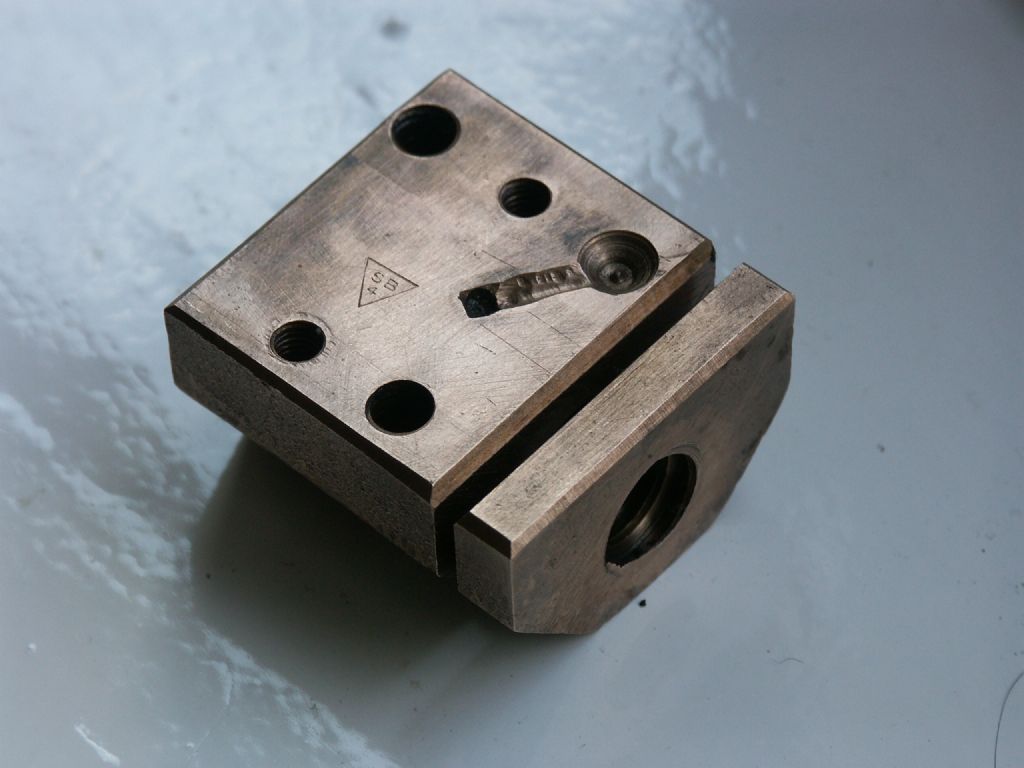
      I’m in the position of having to make a replacement nut for the cross slide on my Smart & Brown lathe.  I am puzzled as to the purpose of the slit at one end that penetrates halfway across the thread.
      Any ideas?

      Regards

      Brian G3oyu.
      Advert
      #21682
      Brian Davies
      Participant
        @briandavies19472
        #49453
        Keith Long
        Participant
          @keithlong89920
          Hi
           
          If you mean the full width slot at 90 deg to the thread axis – is there any provision for applying pressure the the “unsupported” bit to close it up and adjust the backlash – or possibly to insert a backlash “eliminator”? For the angled short slot – a lubrication path maybe?
           
          Keith
          #49458
          Jeff Dayman
          Participant
            @jeffdayman43397
            I’m not sure, but this may be a passive backlash eliminator. the thin end after cutting at the factory could have been given a press or bash to slightly deform it toward the main part of the nut. This would result in a very slight deformation of the thread pitch. When assembled to the leadscrew the thin end would spring back to conform with the thread pitch, but the interference force would take up some backlash. This would be rather rough on the leadscrew, but maybe they used a hardened leadscrew.
             
            On other antilbacklash systems in different machines separate springs and other devices do the same thing.
             
            The angled slot on top is an oilway as Keith mentioned.
            #49462
            Brian Davies
            Participant
              @briandavies19472
              Thank you all for your suggestions, it is much as I thought.  No there is no means of applying pressure to the thin end of the slot once the nut and screw are assembled into the cross slide.  I think the suggestion that a good wack with a hammer to slightly deform the nut prior to assembly is the correct one.
              Regards
              Brian
              #49464
              Keith Long
              Participant
                @keithlong89920
                If you’re making a new nut, is there room to drill and tap 1 or 2 holes parallel to the main screw axis, say 45 degrees up either side form the screw, and insert some smallish machine screw ,csk heads probably, so you can put a bit of squeeze or spread on the bit that’s partially split off to give yourself some backlash adjustment. Another thought if you’re copying the split as well is to make a loose piece that goes in there with a shim to pack it to the size of the slit, and again hold it in place with some small csk screws. Cut the thread in the nut, including the loose piece, then by adjusting the shims you can move the loose piece to and fro in the slit and alter the backlash that way – possibly?
                Keith
                #49472
                Steve Garnett
                Participant
                  @stevegarnett62550

                  I’m intrigued now. Which Smart and Brown is it? On our 1024, the cross-slide backlash is adjustable, and I find it difficult to believe that a firm who produced what is quite a good toolroom lathe with the correct means of adjustment would resort to a ‘bash it’ solution on another one…

                  #49481
                  Brian Davies
                  Participant
                    @briandavies19472
                    Hi
                    Many thanks for the reply and thoughts.  I too have doubts about S&M making something that needed a wack to set it up!  My machine is a Model A and is otherwise a fine machine.  It already performs well on brass and free cutting mild steel.  The problem became apparent when I tried machining silver steel, because it is rather tough the cross slide clearly started to move around on the backlash.
                    I am looking at modifying the new nut to incorporate some backlash adjustment but just how to do this satisfactorily has yet to be decided.  Something similar to your suggestion Keith seems a good possibility.
                    The other thought is to provide a way to lock the cross slide so that it cannot move when traversing along the bed.
                    Brian
                    #49485
                    Steve Garnett
                    Participant
                      @stevegarnett62550
                      The Model A cross-slide looks similar to the 1024 one, but the only cutaway diagram of it I could find shows that it is significantly different underneath, although there is no detail shown of the nut itself – just a solid block.
                       
                      If I recall correctly (it’s a long time since I had it to bits), the 1024 adjustment consists of an extra bit of tapped nut on the end of the nut proper, and it has two radial slots in it so that it can be turned, and then locked in place with a couple of cap head screws. So in theory you could turn rotate it up to the point where the threads bound if you wanted, although ours never quite did that, even right at the end of the slot travel. The other thing about it that I seem to recall is that the extra bit of nut isn’t made of steel, although I’d really have to check that to be sure of what it is.
                       
                      We manage to turn small grooves in stainless tube with the 1024 without too much of a problem, as long as you do it all in one hit, and it doesn’t really give any grief at all once you have the technique sorted.
                      #49492
                      Brian Davies
                      Participant
                        @briandavies19472
                        Thanks for the comments Steve.  I’ve been doing some further research this morning and find that beneath some crud there is a socket head grub screw, in the top of the cross slide, with a cone shape at the bottom that when screwed in does in fact act on the slit thereby opening it out.  This will take up some backlash but how much I don’t know. 
                        So no ‘bash’ with a heavy hammer needed!
                        I am rather confused about the leadscrew dimensions however.  This measures up at exactly 1/2 inch diameter and 8TPI.  Reading Advanced Machine Work it seems that for 1/2 inch the TPI should be 10.  I’m sure it doesn’t matter what the TPI is providing it matches the leadscrew.
                        Fortunately the book goes into the thread shape in great detail as well as the correct shape to grind the cutting tool too.
                        I have an enquiry out for a suitable lump af phosphor bronze and once I have that I will be able to make the replacement.  However I am going to look at the possibility of creating a modified backlash eliminator (I don’t trust my machining too much!)
                        Brian
                        #49517
                        Steve Garnett
                        Participant
                          @stevegarnett62550
                          I’m not at all convinced there’s any absolute standard at all when it comes to leadscrews; diameters, thread pitches or even the thread profile can vary according to manufacturers’ whims, and also according to whether you have a metric one or not. Okay, that seems to be a bit unlikely on a model A… As you say, having the correct pitch for the nut, regardless of what it actually is, is rather more important!
                           
                          As far as the thread itself is concerned, you should check carefully that the thread shape/profile given in that lovely old American publication (that can now be downloaded for free, along with the companion ‘Elements’ book) is actually the same as the UK-manufactured leadscrew’s is; I wouldn’t put it past a UK manufacturer to adopt a slightly different profile as well as ‘non-standard’ TPI!
                          #49518
                          Brian Davies
                          Participant
                            @briandavies19472
                            Thanks for that Steve, I will take care to get the profile as accurate as I can.  I do have a shadow graph machine that at present is not working.  It will pay me to sort this out and then I can take  profile off the leadscrew and be certain that it is right.
                            Brian 
                            #49597
                            Steve Garnett
                            Participant
                              @stevegarnett62550
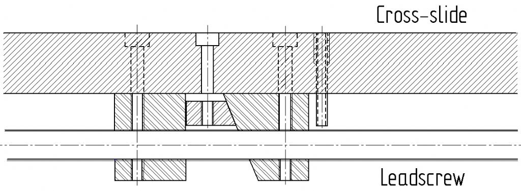
                              Turns out that my memory of the cross-slide backlash adjuster wasn’t quite correct. The one I described is how it works on the top slide, not the cross slide. But since the cross slide one is slightly more interesting, I did a very quick drawing of it, just so you get the idea. This isn’t my idea of a good machine drawing, incidentally – just quick and dirty to show the principle, and with all sorts of things like bolts left out (the bit on the right that I forgot to label and is irrelevant anyway is the oiler hole):
                               

                              The bolt in the centre hole pulls the wedge block towards the cross-slide, forcing the threaded nut blocks either side of it apart – instant backlash elimination.

                              #49603
                              Steve Garnett
                              Participant
                                @stevegarnett62550

                                What I forgot to add was that I much prefer this version of a backlash eliminator to the one that distorts the nut, simply because there is an even axial force on the leadscrew, rather than a potentially distorting one that will cause uneven thread wear in the long run. I don’t know about you, Brian, but if I was going to fabricate a new nut, I would have thought that a version like this would not be too difficult at all to make. Looking back through the thread, it would appear that doing it this way is very similar to Keith Long’s suggestion – only adjustable in situ – always an advantage!

                                #49878
                                Brian Davies
                                Participant
                                  @briandavies19472
                                  Many thanks for all the replies, I’m sorry I was unable to reply sooner but last Monday week I was rushed into hospital with a suspected heart attack.  As it has turned out it wasn’t one but the test done have thrown up a problem that will need sorting.  I managed to escape yesterday and am only now managing to work through several hundred emails!
                                   
                                  I now have a lot of information about cross slide nuts and will digest this in due course and once my problem is solved and I’m back in the workshop I’ll make a decision on how to proceed.
                                   
                                  Kind regards
                                  Brian G3OYU 
                                  #49917
                                  Steve Garnett
                                  Participant
                                    @stevegarnett62550

                                    Best wishes for a speedy full recovery, Brian.

                                    #49923
                                    Brian Davies
                                    Participant
                                      @briandavies19472
                                      Many thanks for that Steve.
                                      Brian 
                                      #50295
                                      Richard Shute
                                      Participant
                                        @richardshute14275

                                        Good evening all,

                                        I’m new here, but a regular on various other fora. I was prompted to respond as I have, some Smart & Brown lathes and a fairly intimate experience of messing about with them. Firstly you may like to consider the Yahoo Smart & Brown group dedicated to these lathes. It is friendly and active and an Operators Manual and Parts Lists are available for free download once you have subscribed, although the details of the feedscrew nut are not very explicit. 

                                        You might also consider talking to Bracehand Ltd near Hitchin (Google it), Chris, the proprietor, was an employee of S&B’s and he bought the S&B name and remaining spares and all their old drawings when they went under. It is not inconceivable he may have a new or ‘good used’ nut and/or feedscrew.

                                        Brian, you have correctly deduced the backlash adjustment on the Mdl A, the taper tipped screw opens the split to reduce the clearance. Make sure that you adjust the nut on an unworn part of the screw or it will bind when you do move to an unworn area. It is probable that most of the backlash can be adjusted out, but any remaining will be due to wear in the scew, not the nut. This will manifest itself as a variation in the backlash over the range of movement. If this is unacceptable, it is the screw more than the nut that needs replacement.

                                        You are pretty much committed to the 8 TPI when you consider the 0~125 graduations on the handwheel. It has caught me out and my chum who’s Mdl A I serviced last year, but unless you change the handwheel as well you are in for some major confusion!

                                        The two part nut that Steve described is used in the top compound slide of both the Mdl A and 1024 as well as some of their other machines. I agree that I prefer either of the two part nut arrangements to the tortured nut on the MdlA, but the original has lasted 60 odd years so it can’t be too bad.

                                        Backlash would not normally give rise to the carriage floating about in use, have you checked the gibb strips for correct adjustment? It might be worth a look.

                                        Rgds

                                        Richard

                                        #50298
                                        Brian Davies
                                        Participant
                                          @briandavies19472
                                          Hi Richard
                                          Many thanks for the info, I have applied to join the S&M group on Yahoo.  I already have a copy of the manual, coutesy of Tony at Lathes.co.uk.
                                          I will certain call Bracehand today and see what they may have available.

                                          The existing gib strip adjusting screws leave a lot to be desired and I am in the process of considering how to improve them.  What I would like to do is replace them with suitably long socket head grub screws but to date I have been unable to find any long enough.
                                          One thing the service manual does not say is the correct proceedure to adjust the gib strip and I’m not sure of the way to do this to realize the best end result.  Perhaps others on this forum could advise me?
                                          Kind regards
                                          Brian
                                          #50301
                                          Richard Shute
                                          Participant
                                            @richardshute14275
                                            Posted by Brian Davies on 31/03/2010 09:18:27:

                                            <…>
                                            One thing the service manual does not say is the correct proceedure to adjust the gib strip and I’m not sure of the way to do this to realize the best end result.  Perhaps others on this forum could advise me?
                                            Kind regards
                                            Brian

                                             Brian,
                                            The tricky part of adjusting the gibbs is the rather irritating locking rings. You need a mildly special tool to deal with them easily – essentially a hollow screw driver. I made tool from a 1/2″ long piece of 5/16 silver steel. Drill an instrument screwdriver diameter hole up the middle and mill the end to leave a 1/32nd wide ridge (inverted groove, but I can’t think of a good word) to engage with the slots in the locking rings. I also put a hex on the other end so I could tighten them. You can then use the tool described to nip up the locking rings whilst holding the adjusting screw with a small screwdriver up the middle.

                                            The way I adjust the gibbs is to set the cross slide to an unworn area of the saddle and tighten all the screws reasonably tight, by hand. Tight finger-tight if you like. This will lock the slide, but will ensure the gibb strip is fully seated as it needs to be pulled down the dowels at the ends. Then successively release each screw and re-tighten it until you just feel it seat and no more. That as such will probably be OK, but if you use the locking rings, you will have to back off the adjusters slightly as the locking rings will take up any clearance in the locking screw threads and tighten the adjustment further. If the saddle is badly worn, you may want to slightly tighten the gibbs some more and accept that it tightens up a little in the unworn area.
                                            Richard

                                            #50302
                                            Brian Davies
                                            Participant
                                              @briandavies19472
                                              Richard
                                              Many thanks for that, yes the locking ring is a pain I had already decided to knock up a hollow driver to deal with the ring, your suggestion looks good and of course it can be hardened and tempered afterwards.
                                              I’ve been onto Bracehand and they are going to get back to me.
                                              Regards
                                              Brian 
                                            Viewing 21 posts - 1 through 21 (of 21 total)
                                            • Please log in to reply to this topic. Registering is free and easy using the links on the menu at the top of this page.

                                            Advert

                                            Latest Replies

                                            Home Forums General Questions Topics

                                            Viewing 25 topics - 1 through 25 (of 25 total)
                                            Viewing 25 topics - 1 through 25 (of 25 total)

                                            View full reply list.

                                            Advert

                                            Newsletter Sign-up