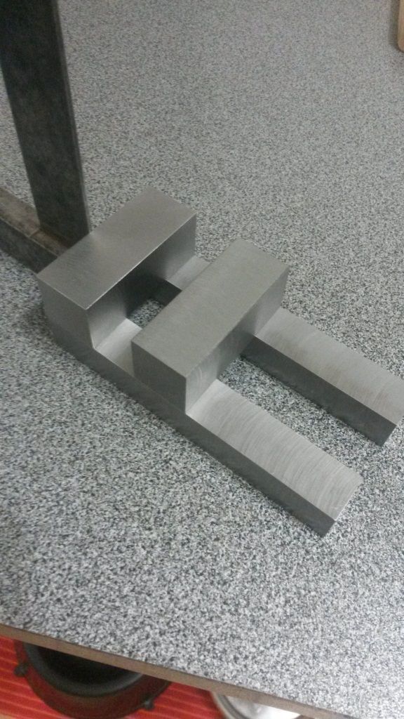
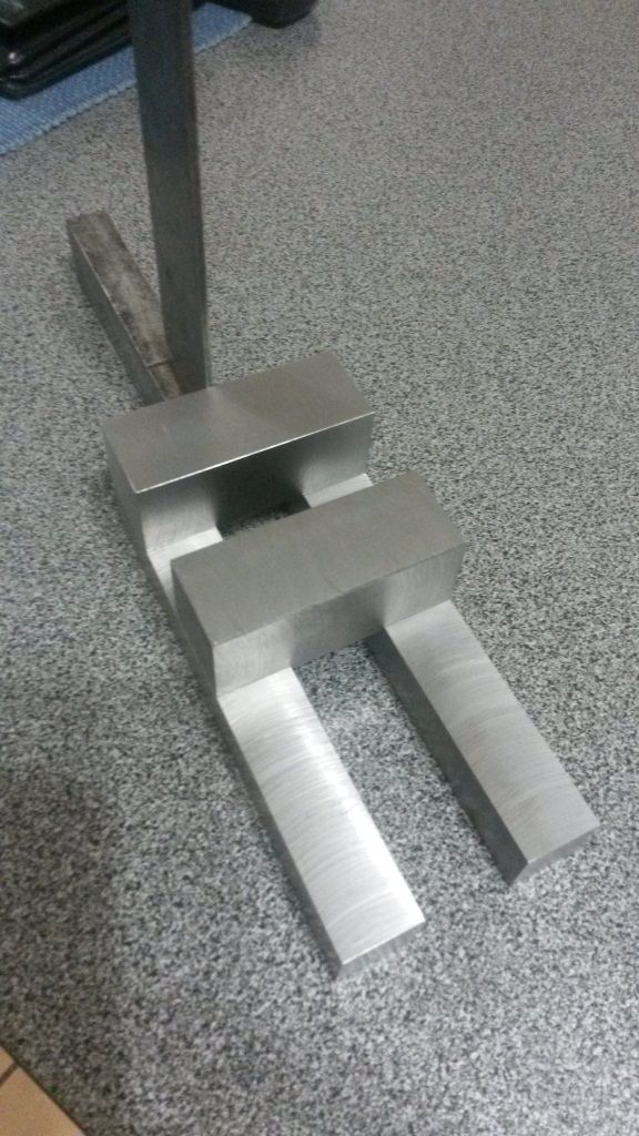
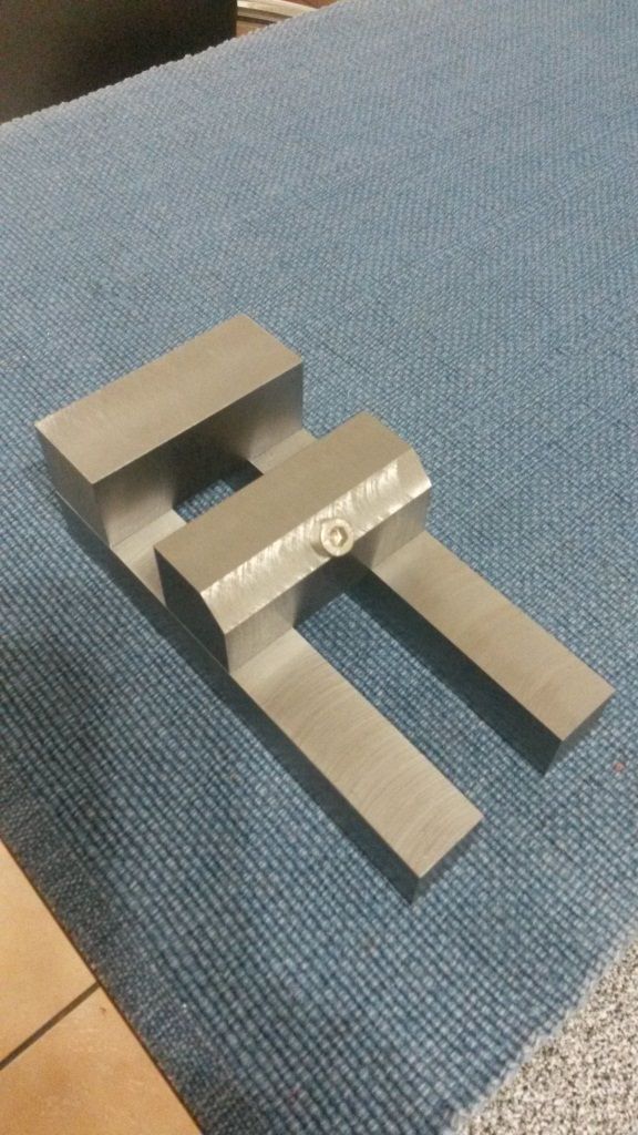
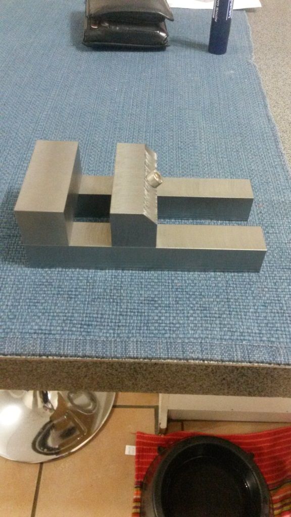
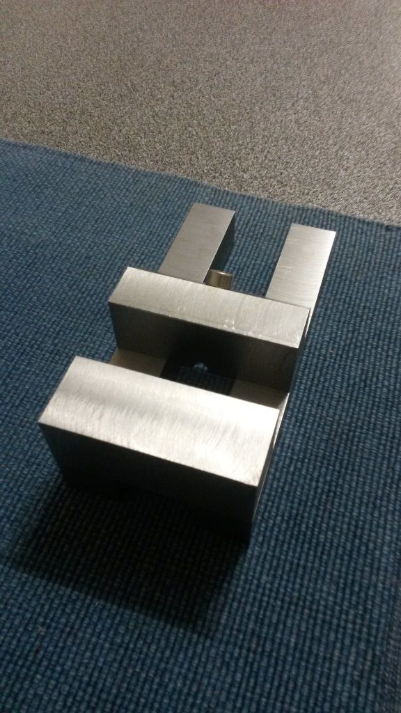
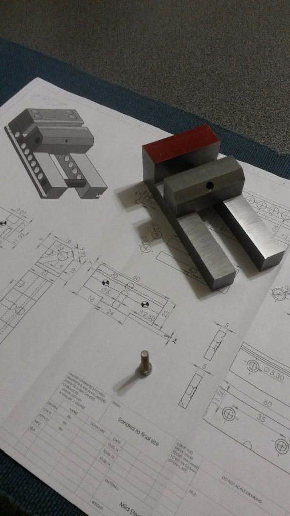
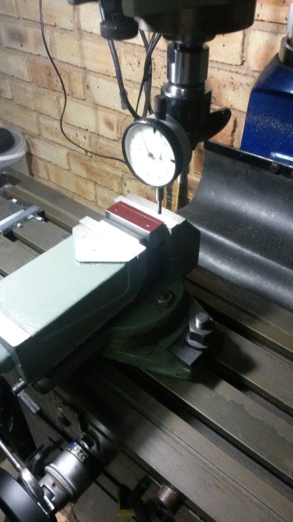
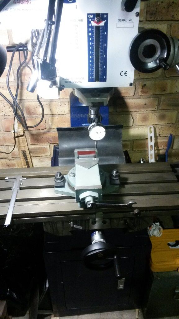
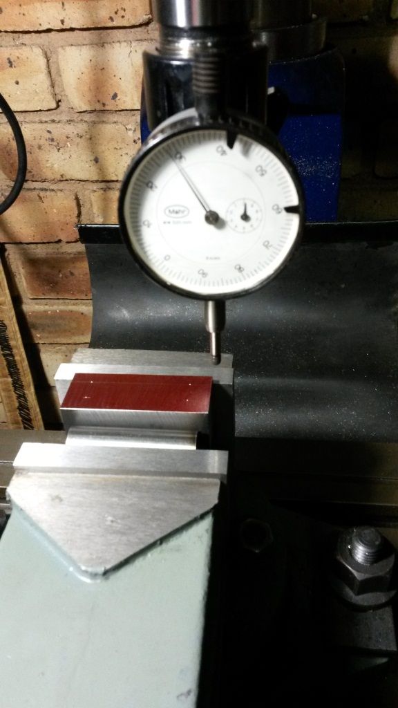
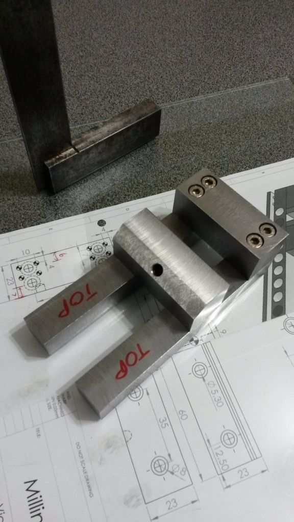
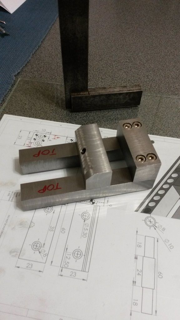
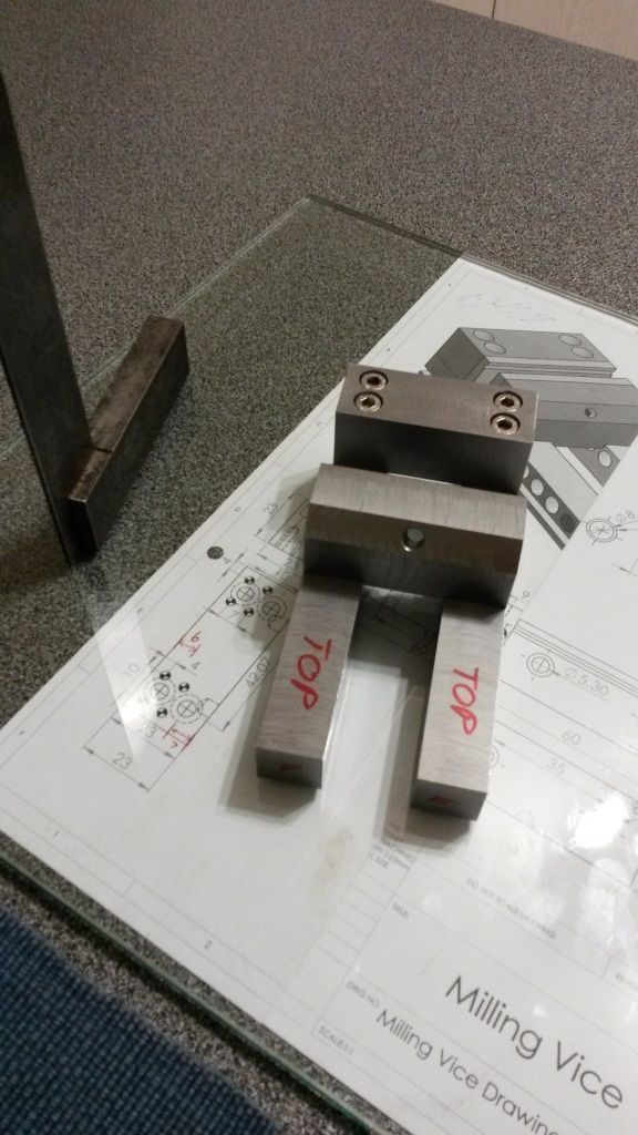
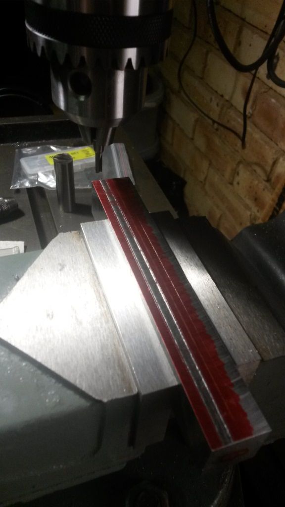
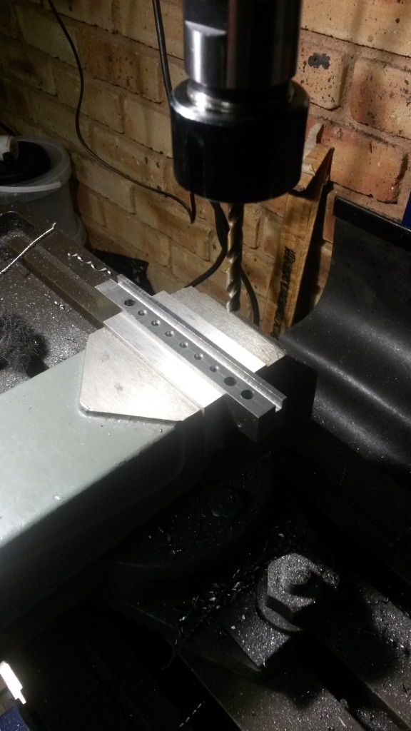
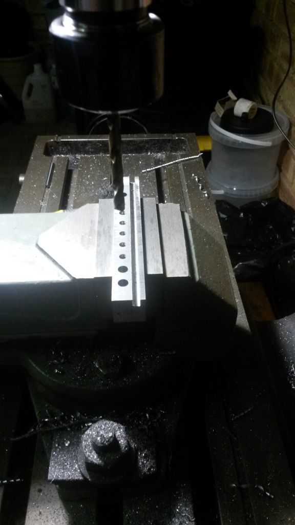
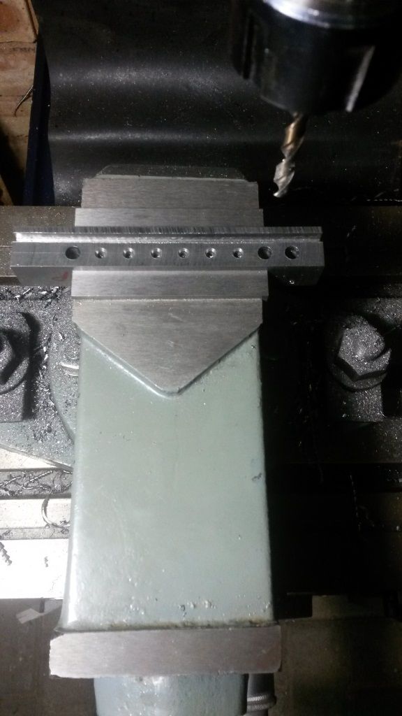
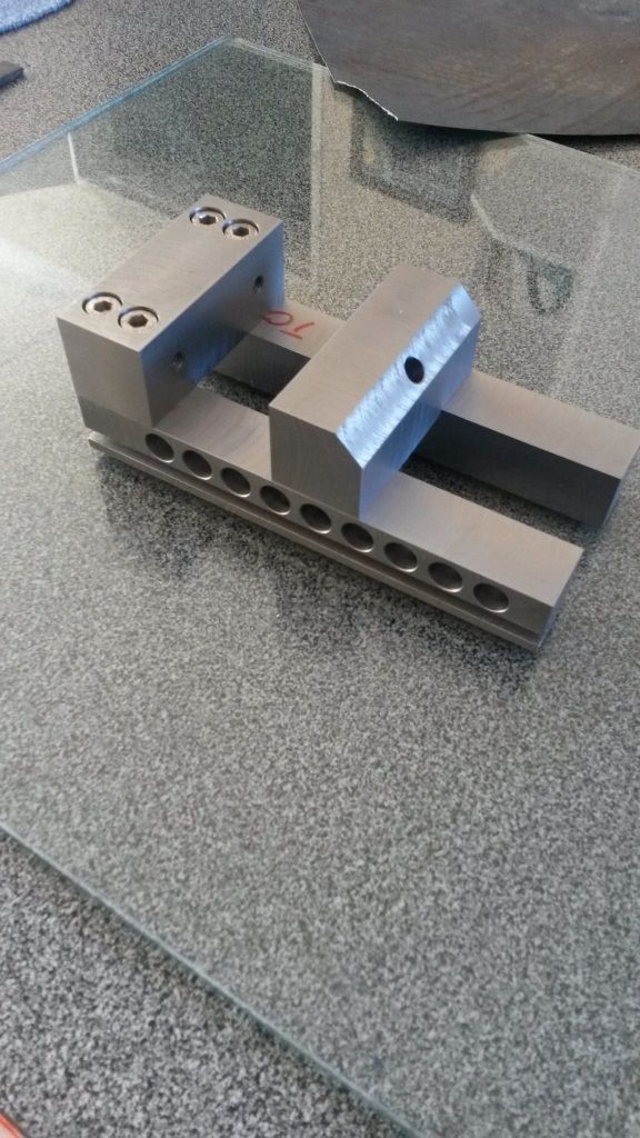
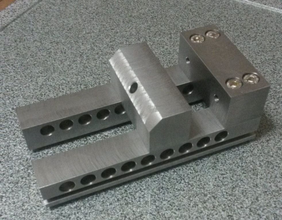
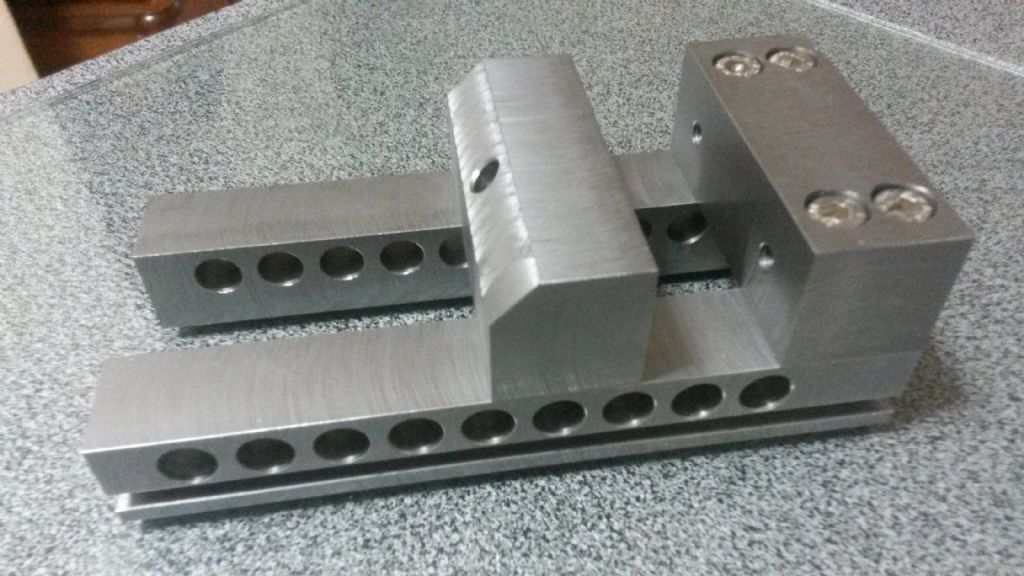
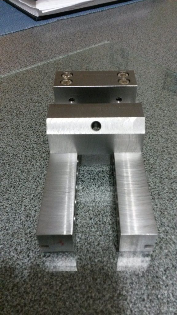
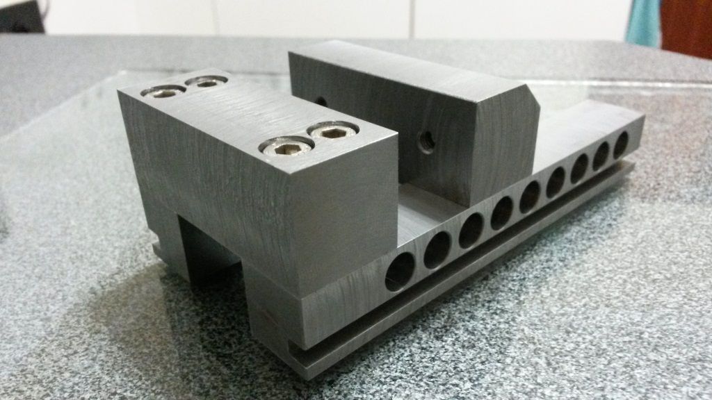
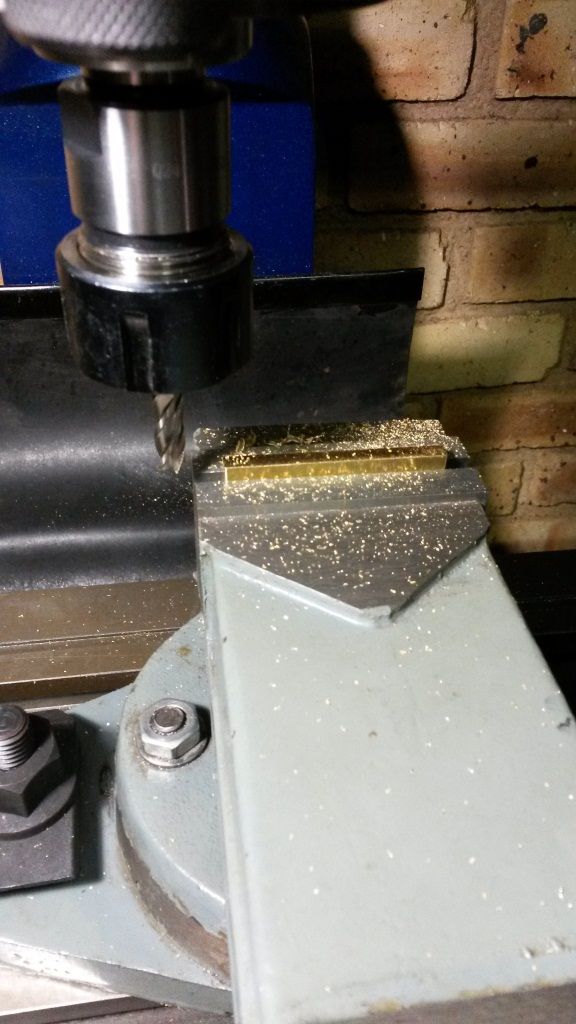
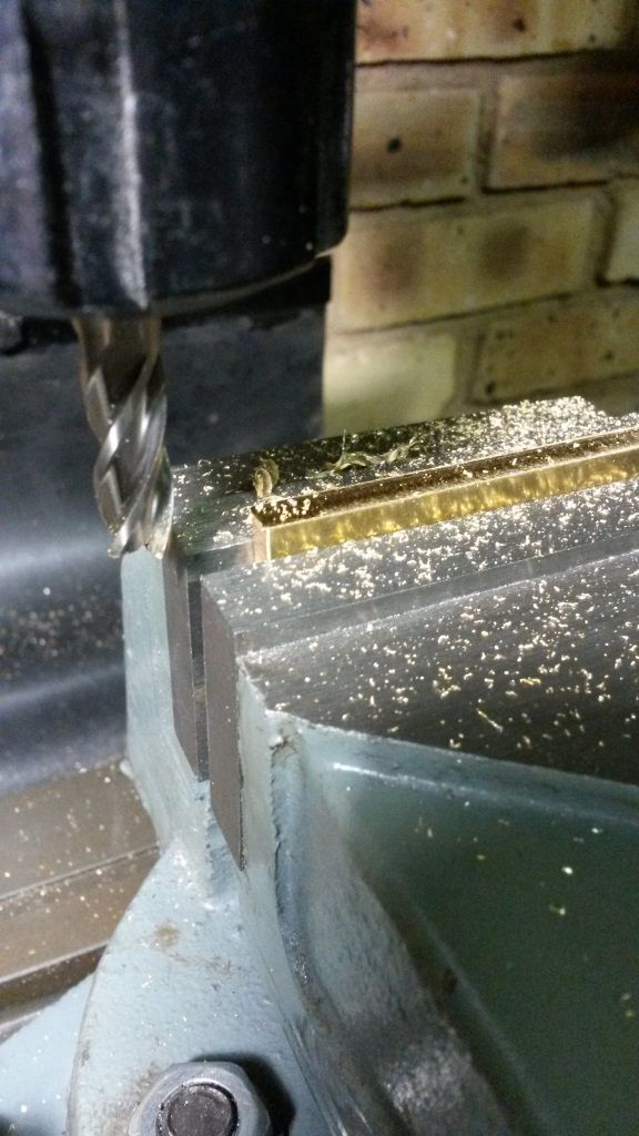
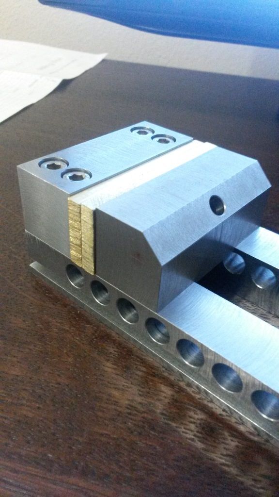
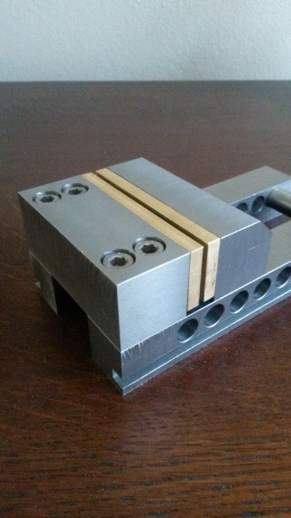
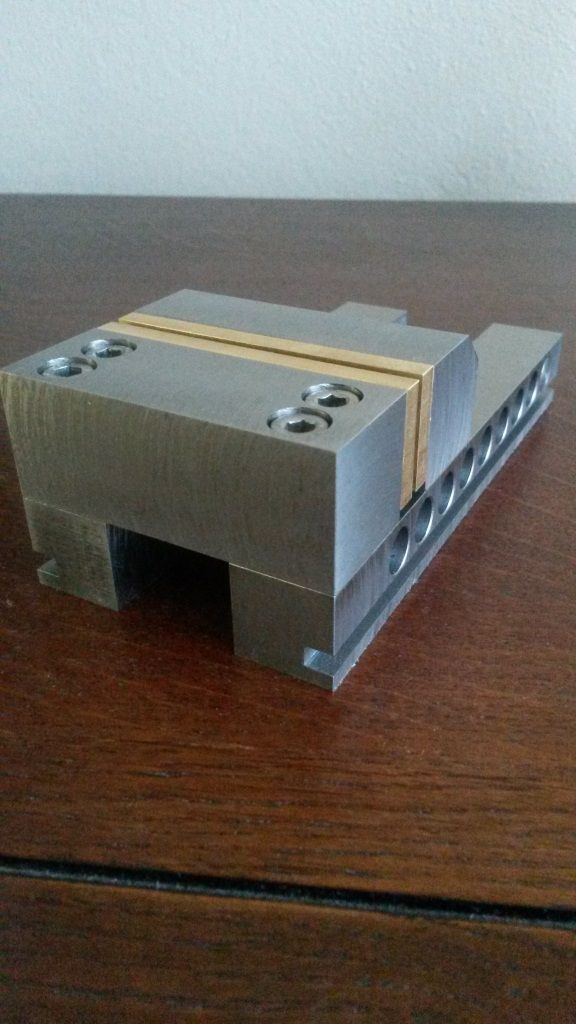
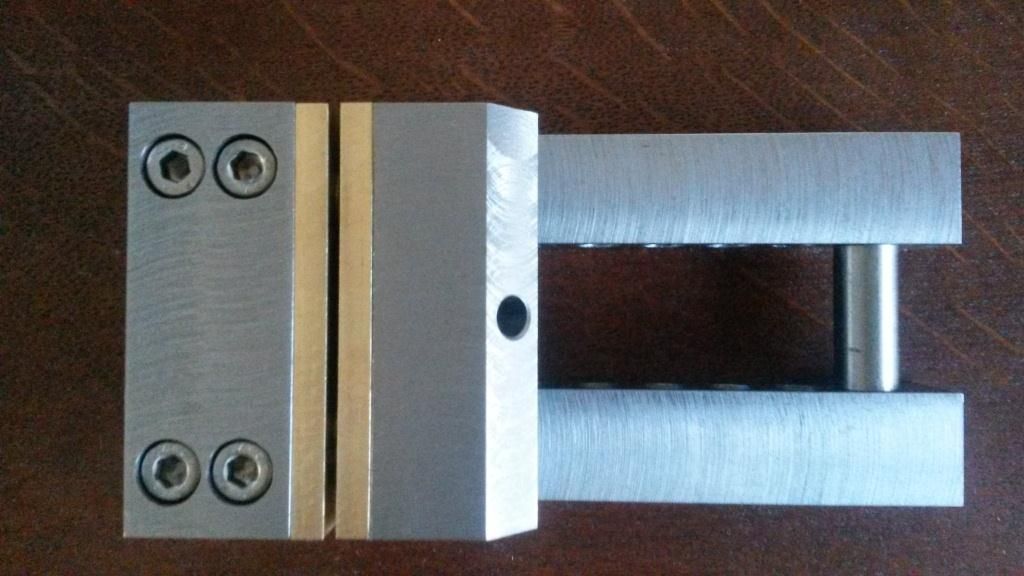
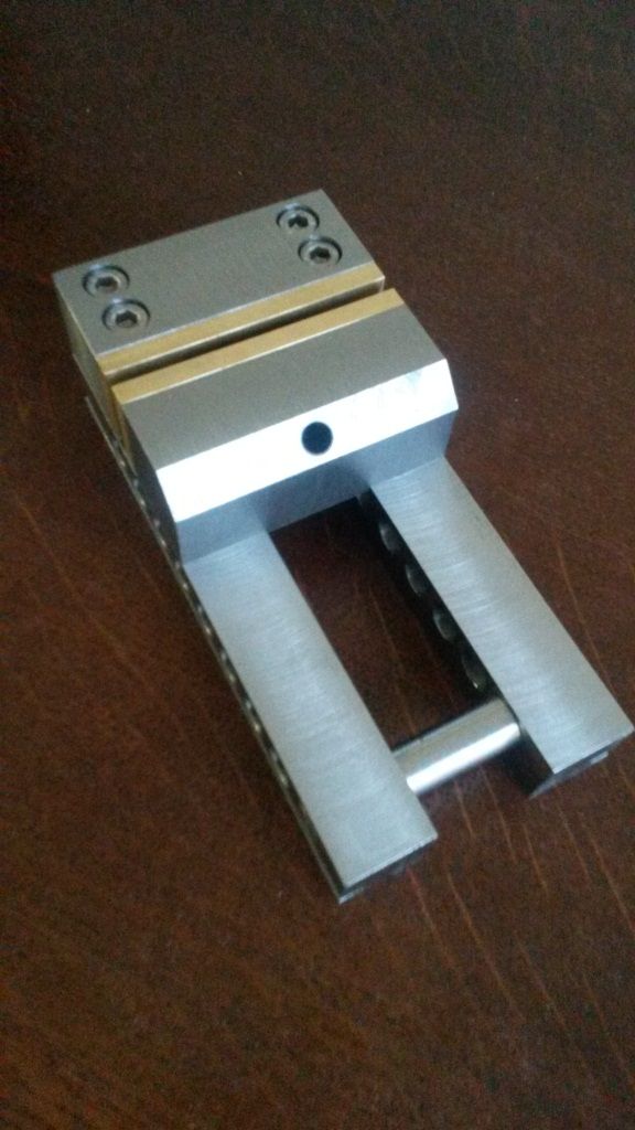
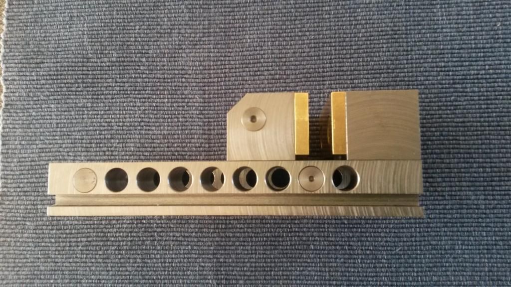
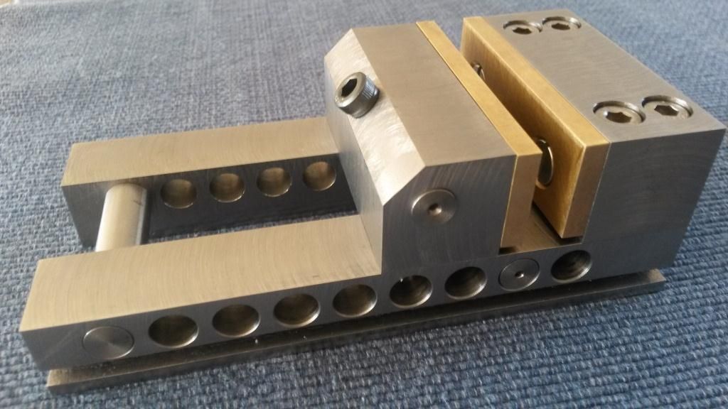
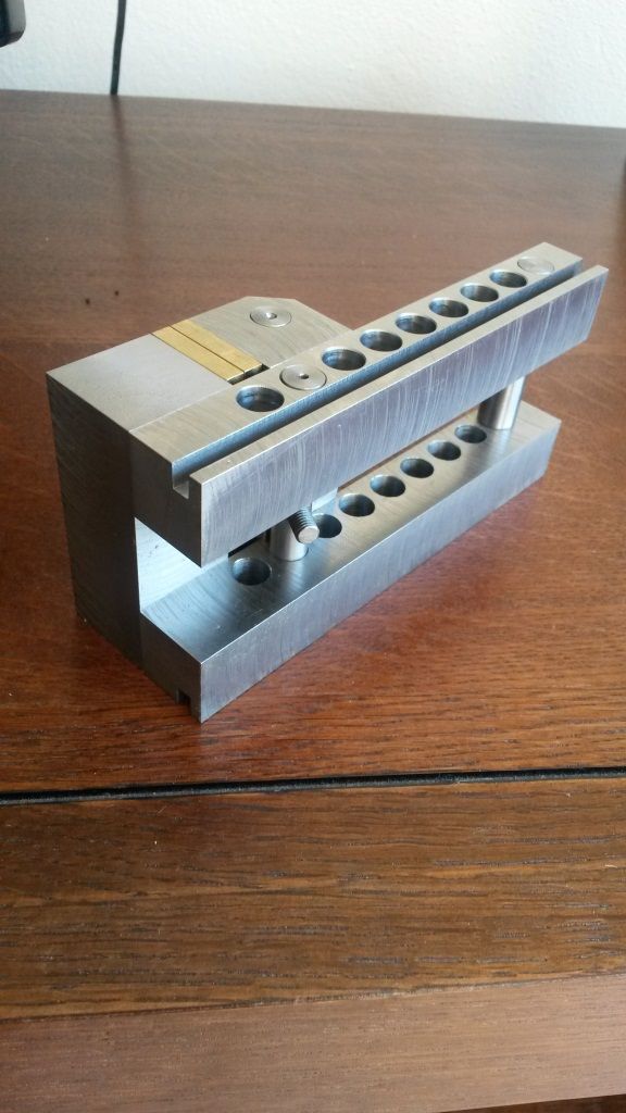
The brass jaws are fixed in place with c/s machine screws and are replacable. One could use copper for softer jaws or hardened jaws as required.
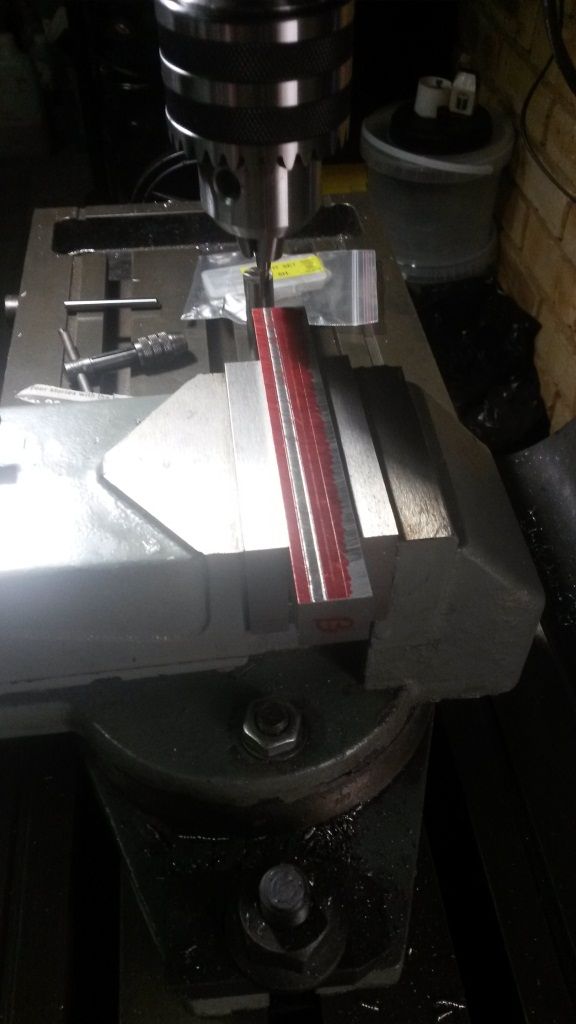
I am afraid that I did not take any photos of the rest of the machining. The moving jaw was set in the four jaw on the lathe and the cross hole drilled for the cross bar.
The cross bars for the moving jaw, the base spreader and the moving lock bar were machined from 10mm silver steel and or 8mm 304 stainless steel depending on the size required.
One fault I did find in the design is the hole in the top of the moving jaw. With the pivot at the cross bar, the jaw did not originally have enough movement forward and backward making the vice useless. At first I relieved the underside of the moving jaw as other designs show. This did not work due to the pivot being lower down than the top of the hole in the moving jaw. Modern vices of this design have a hemispherical washer at the top which pivots in a round bottomed hole allowing large movements in both directions.
As this is not the case here, the hole was enlarged at 45 degrees from the top improving matters dramatically.
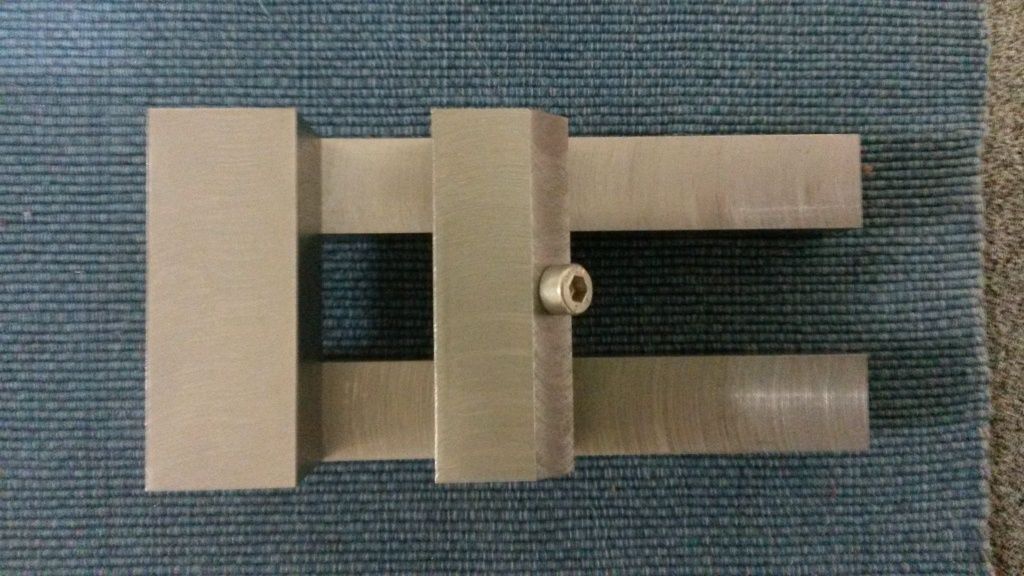
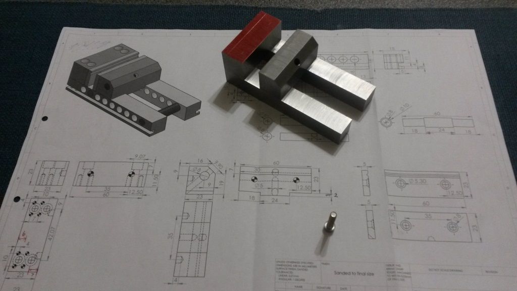
See the photos below.


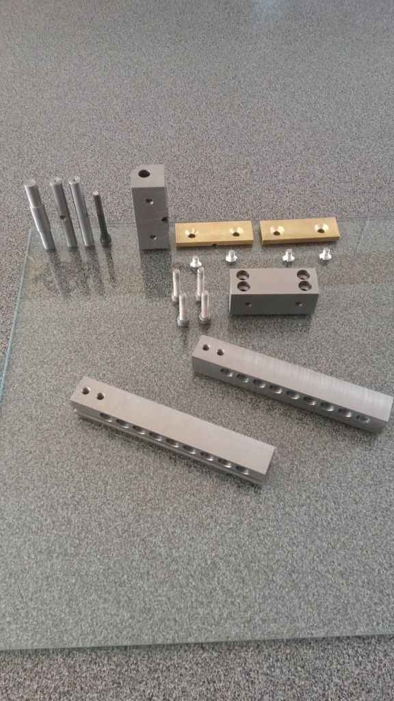
Above is a photo of the entire vice disassembled.

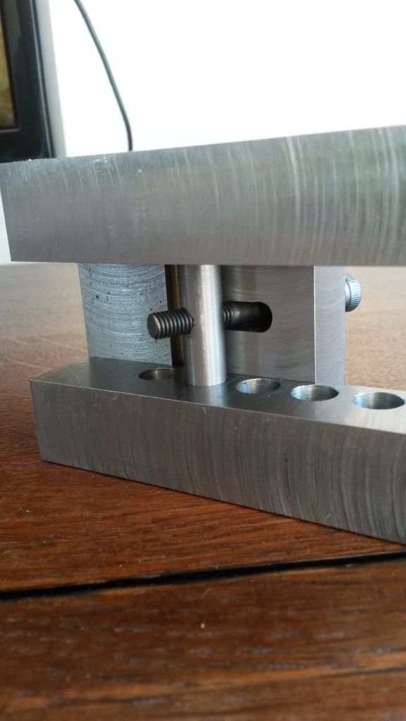
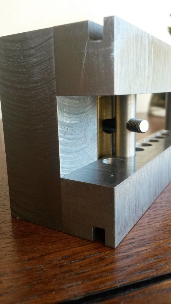
The hole at the bottom of the moving jaw, machined to allow more movement. (This did not help much and was a waste of time).

Here you can see how the vice is locked, using a machine screw through the movable cross bar.

“Bill Hancox”.


