Single wire capacitive sensors.

Advert

Single wire capacitive sensors.

Home Forums Electronics in the Workshop Single wire capacitive sensors.

Viewing 8 posts - 1 through 8 (of 8 total)
  • Author
    Posts
  • #580955
    Robin Graham
    Participant
      @robingraham42208

      I have had an unusual request from a 'performer' in my town. She wants to adapt a sort of robotic toy horse for a piece of theatre. If interested you can see the toy horse doing its thing here and an example of the proposed theatre here.

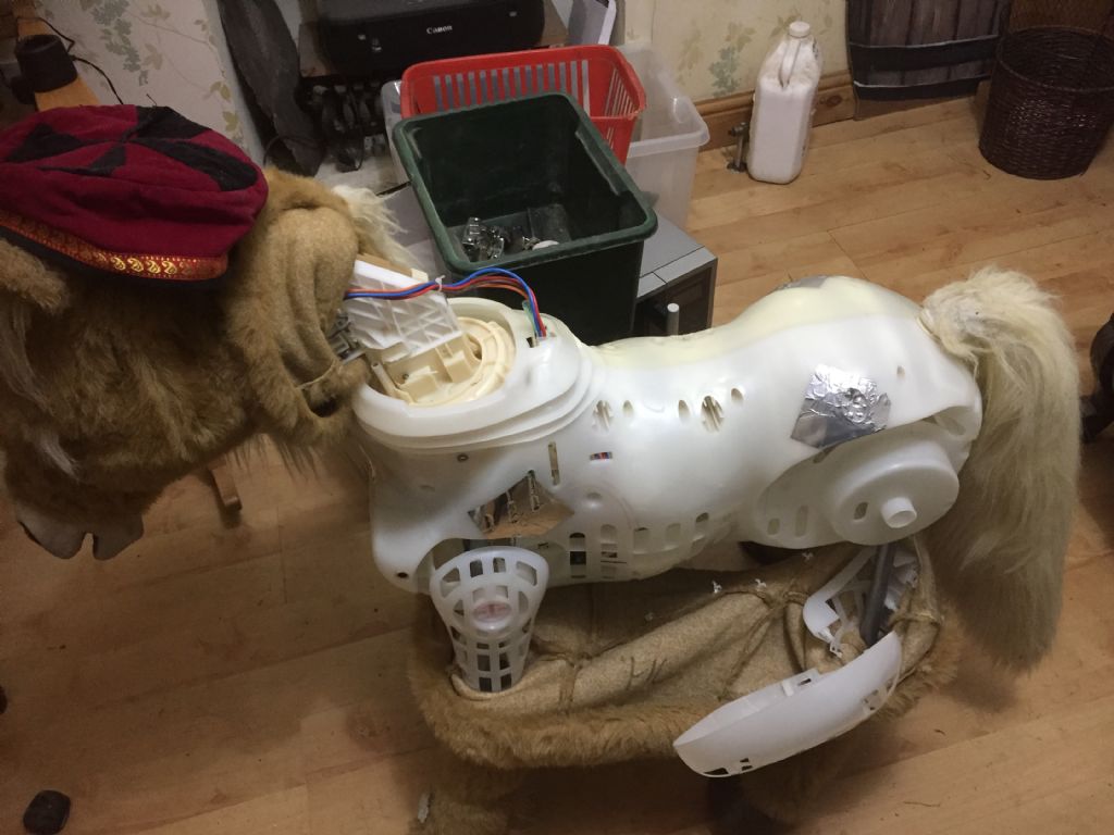
      The toy responds to sensors on various parts of its body. These are simply aluminium foil patches connected by single wires to the control board in the body:

      butterscotch2.jpg

      I assume that these must be capacitive sensors. For practical purposes it probably doesn't matter too much, as I can just move the sensors to where the client wants in a new framework. But how do they work? Can any of the electronics boffins on here explain?

      Robin.


      Edited By Robin Graham on 18/01/2022 00:51:43

      Advert
      #32232
      Robin Graham
      Participant
        @robingraham42208
        #580958
        Joseph Noci 1
        Participant
          @josephnoci1

          Robin,

          Cannot be said definitively as there are dozens of ways of doing that..two most likely options are a 'mains-hum' detector – lots of AC mains 50hz noise about, picked up by our bodies, and when your hand is brought near the foil, a high gain amplifier with possibly a 50hz bandpass filter amplifies this hum, which is then detected ( diode type envelope detector, sort of like am AM radio audio demodulator).

          2nd possibility is more complex and a bit more reliable – the wire and foil is part of an RF oscillator such that when you contact or come near the foil, the oscillator is de-tuned and either the change in frequency or amplitude is detected. More reliable since if the performances are given in a rural setting, maybe there is not enough AC hum 'in the air'…This along the line of the Therimin musical instruments.

          The more modern technologies use many techniques – such as measuring capacitance change as you touch the sensor area – there are IC's that do all that in a small package – often used for touch sensitive keyboards, home appliance panel touch keys, etc.

          As to moving the sensors and keeping the sensing result, I would suspect you have a good chance of success.

          Try to make sure there is no metallic object behind the area you you wish to fit the foil – likewise, don't route the wire near metal bits, etc. Should be easy to test.

          If you want to know more about what you have, try trace a little of the circuit from where the foil wires attach to the board – probably through a capacitor and then to either a transistor amplifier of op-amp amplifier I would think..I suspect this setup will be the mains hum detection type of setup.

          Joe

          #581123
          Robin Graham
          Participant
            @robingraham42208

            Thanks for your reply Joe. I knew about the RF oscillator thing, but I doubted that this toy was that sophisticated. I didn't know about the AC hum thing though.

            Before posting I did a bit of research and found a circuit which uses a simple voltage divider and a Schmitt trigger. I wondered if that might be the way it worked – it is here . I also found a recipe for an Arduino based sensor here . Both of these are DC as far as I can see.

            Can you shed any light on how these work?

            Best regards, Robin.

            Edited By Robin Graham on 19/01/2022 01:11:55

            #581139
            John Haine
            Participant
              @johnhaine32865
              #581141
              Joseph Noci 1
              Participant
                @josephnoci1

                Robin,

                the first link ( schmitt trigger) falls in the category of the 'hum detector' except it detects any voltage transient level – most often your body with develop detectable levels of static electricity and that will trigger the schmitt. Removing finger contact will cause the capacitor in that circuit to discharge, removing the voltage on the schmitt input, and the output will then fall back to its inactive state.

                That circuit will generate a 50Hz pulsing output if you are in proximity of a strong AC field and you touch the pad – that 50Hz signal will appear on the schmitt input an the output will pulse. How that signal is/can be used depends on the electronics in the control board.

                That arduino implementation is more complex. A digital output pin generates a fixed pulse train. An input pin feeds a timer/counter. If the two pins are connected together, the timer will count a number of processor clocks, which equate to the time interval between the pulses on the output pin.

                So if you vary the period of the output pin pulses, the counter value will vary as well.

                Now connect the output pin to the input pin through a large value resistor, and place a capacitor ( the sense pad or foil) on the input pin. Now you have an RC network which delays the arrival of the pulse on the input pin, allowing the counter/timer to clock up a larger value. Add more capacitance ( your finger, a capacitive increase through your body to the air and ground) and the pulse is delayed further, and the count value increases more. That count is read and the finger contact detection computed…

                The link John Haine attached is in the category of IC sensors I mentioned in my first post – there are many of that type available – However, I guess for your purpose you don't really want to start experimenting with other types as it may have influence on the interface with the controller board.

                As a test, just connect a wire to one of the pads, and extend the wire say 200mm to another spot on the torso and add another foil pad to the wire end and try it – I am sure it will work.

                #581145
                John Haine
                Participant
                  @johnhaine32865

                  It was just that the link had some explanatory text, and it's quite likely that the unit uses that sort of device.

                  #581304
                  Robin Graham
                  Participant
                    @robingraham42208

                    Joe – many thanks for taking the time to explain in detail the two circuits I linked to. My knowledge of practical electronics is rudimentary but I have enough general physics to follow your explanations and I think I now understand how they work. Following your suggestion (sort of) I stuck a 250mm length of self-adhesive copper tape (just because I happen to have a roll and it was easy) to one of the sensor pads, and touching the strip anywhere works fine – despite the layer of adhesive. I'm now pretty confident that I can make this work.

                    John – thanks for the link to the Adafruit site. Very interesting, but as as Joe guessed I'm not, at the moment anyway, planning to replace the control board, just redistribute the sensors on a new frame. It's a tempting prospect though! My reason for starting this was just curiosity about how these things work.

                    I'll probably have further questions when I get the animal 'on the slab' to extract the processor.

                    Robin.

                    Edited By Robin Graham on 20/01/2022 00:24:33

                  Viewing 8 posts - 1 through 8 (of 8 total)
                  • Please log in to reply to this topic. Registering is free and easy using the links on the menu at the top of this page.

                  Advert

                  Latest Replies

                  Viewing 25 topics - 1 through 25 (of 25 total)
                  Viewing 25 topics - 1 through 25 (of 25 total)

                  View full reply list.

                  Advert

                  Newsletter Sign-up