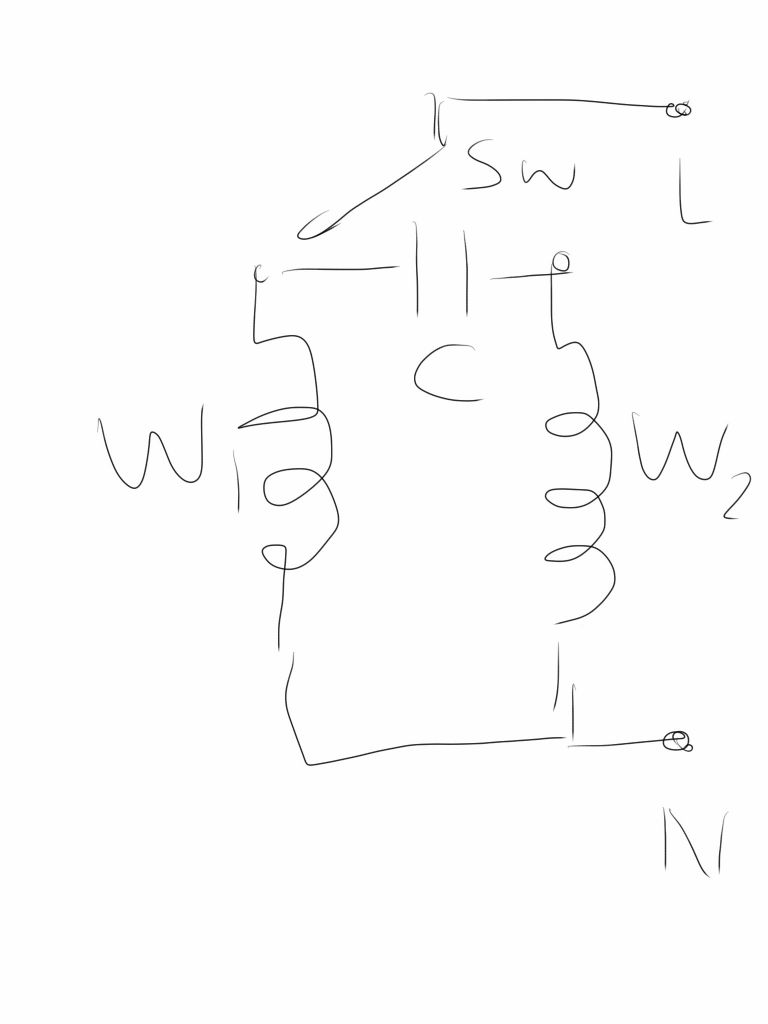
Single phase induction motor speed control
Single phase induction motor speed control
- This topic has 11 replies, 6 voices, and was last updated 30 January 2018 at 10:40 by
John Haine.
Viewing 12 posts - 1 through 12 (of 12 total)
Viewing 12 posts - 1 through 12 (of 12 total)
- Please log in to reply to this topic. Registering is free and easy using the links on the menu at the top of this page.
Latest Replies
Viewing 25 topics - 1 through 25 (of 25 total)
-
- Topic
- Voices
- Last Post
Viewing 25 topics - 1 through 25 (of 25 total)
Latest Issue
Newsletter Sign-up
Latest Replies
- Diving in to ATC?
- What Did You Do Today 2025
- Measuring a double Vee lathe bed Vee position
- Please direct me to where I can find an engineer to do some bespoke work
- Making Unimat DB/SL Steadies
- Bad design, or am I missing something?
- Lidl castors
- Hopeless…Alibre Ass
- Polishing compounds for stainless steel (mild abrasives))
- Alternative to ARC


