Simpling / Starting Valve Help Sought

Advert

Simpling / Starting Valve Help Sought

Home Forums Traction engines Simpling / Starting Valve Help Sought

Viewing 10 posts - 1 through 10 (of 10 total)
  • Author
    Posts
  • #2950
    Nigel Graham 2
    Participant
      @nigelgraham2
      Advert
      #492827
      Nigel Graham 2
      Participant
        @nigelgraham2

        Compound Engine for a Hindley steam-wagon – no drawings available just 100+yo advertising photos, of which several suggest the regulator was an ordinary gate-valve bolted to the boiler top, and one suggests the simpling-valve was on the outside of the HP valve-chest.

        Can anyone please tell me how these things are actually meant to work?

        I cannot find any general principles for these fittings.

        I can find only scant drawings and information suggesting various basic forms. The drawings are only cylinder sections showing complex multi-port plug-cocks within tangles of untraceable cavities and passages in the cylinder casting.

        Assuming I have identified the controls correctly, the photo I have suggests the alleged starting-valve is formed in the elbow connecting the live-steam pipe to the valve-chest wall, and may open a take-off / restrictor that dives into the mysterious innards, presumably to the LP valve-chest.

        That seems inadequate though.

        That alone would theoretically give a double-high setting, but negated by putting live steam back against the HP exhaust. Yet this engine seems to have just this single tappet-valve operated by a short lever, on the outside of the unit. (Unless it is actually the regulator – so why the prominent gate-valve upstream of it?)

        There is also a curious fitting on the bottom corner of the HP valve-chest, apparently a valve on a pipe that vanishes round the corner of the engine case. If it is a valve it has no obvious handle or control-link, though might be a drain-cock independent of the linked cylinder-drains.

        '

        I would expect at least two valves for basic double-high working: one feeding HP steam to both cylinders with a restricted flow to the LP, while the other diverts the HP cylinder's exhaust straight to the main engine exhaust. (The restrictor is necessary for approximately equal piston forces in D-H working.)

        By two valves, I mean either literally that, linked by a control-rod, or a single piece of metal amid appropriate ports and passages.

        SO….

        Whilst I still have some grey hairs, I would be very grateful if someone can tell me the basic layouts of double-high valves.

        I know what they do… I need to know how they do it!

        #492839
        Anonymous

          This has been discussed at length recently on the TractionTalk forum:

          **LINK**

          Although I believe you have to be a member to be able to read posts. In summary it's not simple (pardon the pun) as every manufacturer did something different, often on different engines.

          My simple understanding is as follows. A starting valve allows boiler pressure steam, from before the regulator, to be applied to the low pressure cylinder. On a DCC engine this allows it to be started when the HP cylinder is on dead centre. External starting valves are quite small with restricted pipes so wouldn't be able to run the LP cylinder at full power for sustained periods.

          As you say a simpling valve is internal to the cylinder and connects the HP exhaust to the chimney. For running as two singles in parallel one needs both a starting valve and simpling valve to be operated.

          On my SCC there's a starting valve, although I prefer to call it a singling valve as if the engine is on dead centre applying steam pressure to the LP cylinder won't help to start the engine. I'm told that this valve (and presumably a proper starting valve) is used in quick bursts to provide some torque for manoeuvring in tight spaces. Note that the valve bypasses the regulator so the valve can be used with the regulator closed. Presumably something one would do if space was limited.

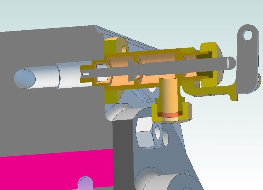
          This is a sectional CAD model of my design of singling valve for the Burrell, based on full size:

          singling valve assembly.jpg

          Hope that at least helps in part.

          Andrew

          #492852
          John Olsen
          Participant
            @johnolsen79199

            Like most things, there are more than one way to do this. The simplest is just a valve that lets you put a shot of HP steam into the LP cylinder. As you say, this will put back pressure on the HP, but since that was presumably on dead centre, that won't matter, the LP will kick the engine over and off you go. That is what I have done on my steam launch.

            The other approach is a more complex valve to divert the HP exhaust to the stack (or condenser) and apply HP steam direct to the LP cylinder. This would be a better approach for an engine that has to start and pull a heavy load, maybe up a grade for some time, like a traction engine or a locomotive. It does need a much more complex valve arrangement. That could affect the steam flow at high speeds, but that is not likely to be a concern on a model, which is not going to be looking for maximum power at high speed for long periods. In simple mode it will of course give greatly increased steam consumption, but since it would only be used when going slow, that should not be a problem.

            John

            #492867
            duncan webster 1
            Participant
              @duncanwebster1

              Wardale in his book about the Red Devil refers to Herdinger? starting valves, which I seem to remember injected live steam half way along the bore, but of course that was a simple expansion engine, he was trying to artificially increase the rather short maximum cut off. I can dig it out if it is of interest

              #492869
              duncan webster 1
              Participant
                @duncanwebster1

                Thinking about it some more that's not what you want for kicking a compound over dead centre, ignore me

                #492961
                Howard Lewis
                Participant
                  @howardlewis46836

                  Not a steam man, but I thought that De Glehn compounds, (Locos ) used the simpling valve to admit steam to the LP cylinder, so that both cylinders took steam from downstream of the regulator, to provide extra torque for starting. Once the loco was moving, the simpling valve was closed and the engine then ran as a compound.

                  Howard

                  #493051
                  Nigel Graham 2
                  Participant
                    @nigelgraham2

                    Thank you chaps.

                    There certainly was quite a variety of these things. One maker, Foden I think, provided three different modes: double-high, LP-only as a single-cylinder, and normal compound!

                    It was the extra torque for starting from rest I was thinking about, and I must admit I had not considered the dead-centre problem. On the Hindley wagon the flywheel is exposed but below the floor and well inside the chassis so you can't use the overtype driver's dodge of manually pulling it round a bit.

                    Andrew – thank you for the drawing but I'm afraid it still leaves me puzzled because whilst that shows the valve itself and the main part is clear enough, I don't know the steam flows when it's in either of its positions, or what that arrangement on the valve's tail does.

                    John – to the best of my knowledge, compound traction-engines and locos were never intended to be worked in double-high for more than enough to get them moving, and indeed to take them off dead-centre. They were designed to give their rated power output in compound mode.

                    Also, the enclosed, inverted-vertical engine on my wagon is designed to run fast in compound mode for normal driving for long periods. It was up to 400rpm on the full size, though what my third-size replica might do is anyone's guess!

                    Nevertheless, I think what you say is the way to go – a control that turns the engine into twin simple-expansion mode by a live-steam feed to the LP valve-chest and HP exhaust diverter. That's presumably 2 valves (physically separate or one-piece) I'd think respectively On/Off and Either/Or, the latter removing the back-pressure problem. However, when I try drawing such a thing I cannot help thinking the original ones must be simpler (even if inside very complex cored castings).

                    #493138
                    Anonymous

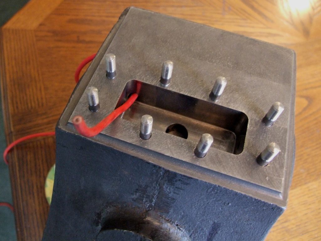
                      The steam flows from the regulator chest (bypassing the regulator) through passageways in the cylinder to the back of the valve. As per the red wire:

                      singling valve inlet.jpg

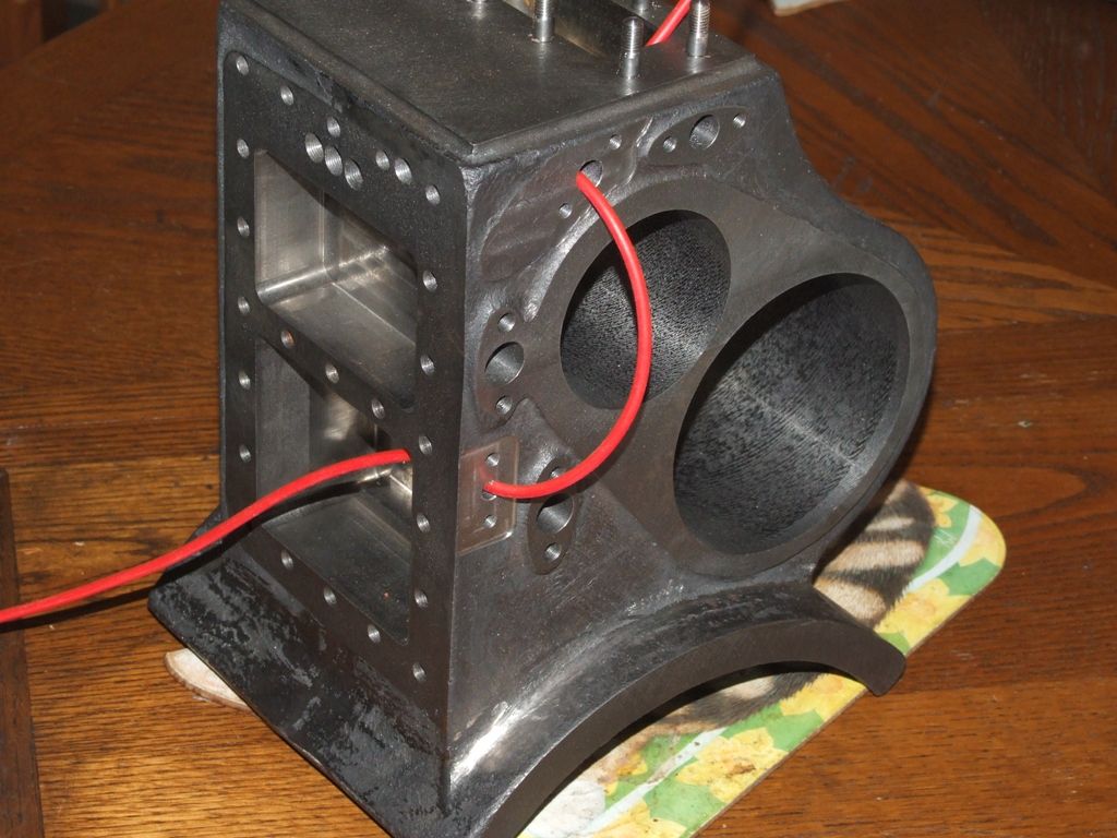
                      In the CAD model the valve is shown closed. When open the steam flows through the valve to the downward facing union to a pipe. The pipe then connects to a flange on the cylinder rear face and a hole that goes into the LP valve chest, again follow the red wire:

                      singling valve outlet.jpg

                      Although not shown in the CAD model the valve is spring loaded shut. On the fullsize engine the pipe from the valve outlet to the LP valve chest is 3/4" OD, which has a small area compared to the normal flow through the valve passageways.

                      The singling valve is operated by a push button on the regulator assembly; the brass knob in this picture:

                      regulator_me.jpg

                      Again, although I haven't made it yet the push button is spring loaded against the rod bushing top right, on the spectacle plate. In use it is intended that the valve is used with quick 'blips' of the operating button, usually with the regulator closed. If nothing else the passageways are not large enough for sustained running of the LP cylinder at nominally full steam pressure.

                      Andrew

                      #493270
                      Nigel Graham 2
                      Participant
                        @nigelgraham2

                        Thank you very much Andrew.

                        So effectively it momentarily runs the engine as a single-cylinder, with the LP cylinder doing the work but with a restricted feed, enough to get things moving.


                        The photo below was one taken by the manufacturers, looking onto the back of the inverted-vertical engine with the HP cylinder on the offside end.

                        The steam take-off on the boiler is the dark-shaded elbow followed by a globe-valve I take to be the regulator, not obvious on this picture but shown by the bolted flange. From that the steam enters the upright column rising from the rear face of the HP valve-chest, with a displacement lubricator above.

                        What I take to be the sampling or starting-valve is the fitting on the valve-chest face itself,. with the short, vertical lever that on the original would have been to the driver's side. (The curved lever below seems to be the reverser.)

                        The cylinder drains are clear enough but the object on the lower outer corner of the LP valve-chest is something of a puzzle.

                        The flywheel is partially visible, down below the driver's seat.

                        The two small covers on the engine's main cover-plate (which is "quickly detachable" it says in the catalogue) are clearly extensions to give room for the expansion-links, but what the little "periscopes" on them do, is anyone's guesshindley engine.jpg!

                        Edited By Nigel Graham 2 on 28/08/2020 22:39:47

                      Viewing 10 posts - 1 through 10 (of 10 total)
                      • Please log in to reply to this topic. Registering is free and easy using the links on the menu at the top of this page.

                      Advert

                      Latest Replies

                      Home Forums Traction engines Topics

                      Viewing 25 topics - 1 through 25 (of 25 total)
                      Viewing 25 topics - 1 through 25 (of 25 total)

                      View full reply list.

                      Advert

                      Newsletter Sign-up