Simple PCB layout software

Advert

Simple PCB layout software

Home Forums Electronics in the Workshop Simple PCB layout software

Viewing 25 posts - 1 through 25 (of 34 total)
  • Author
    Posts
  • #629623
    John Haine
    Participant
      @johnhaine32865

      A question for the other electronically reminded. I build a number of electronic assemblies and I usually end up using Veroboard just like I started out 50 years ago! It isn't ideal and I would prefer to make simple PCBs, as I have the means to make them by isolation routing on the CNC mill. I've used DesignSpark PCB in the past to try to do this and was successful but it's a bit tortuous. I've also used KiCAD for schematic capture which is nice to use but often one finds that there isn't a library component that matches what I need. For example there's only a limited number of Arduinos. And the process to generate a new element is almost impossible to even find out how to start!

      So does anyone have any recommendations for a suitable tool / toolchain please? I think my requirements are…

      • A good selection of standard components in the library (CMOS/TTL, transistors and the usual passives, processors)
      • The ability to add standard footprints like pin-numbered DIL to which one can connect, so at least it would be possible to generate a schematic
      • Auto-layout would be nice but my circuits are generally simple to manual layout wouldn't be too much of problem
      • Output to Gerber files is fine as there are post-processors to turn those into g-code, but if that was internal it would be a bonus
      • Ideally freeware!

      Thanks in advance for your suggestions!

      Advert
      #32312
      John Haine
      Participant
        @johnhaine32865
        #629626
        Bountyboy
        Participant
          @bountyboy

          Hello John,

          I've not used it but I've heard good things about

          Fritzing

          Maybe worth a look.

          #629643
          John Hinkley
          Participant
            @johnhinkley26699

            John,

            There is a program called Eagle produced by Autodesk which allows a personal use free download in the style of Fusion 360 from the same stable. The web site states :

            " EAGLE free download is a limited version for hobbyists including 2 schematic sheets, 2 signal layers, and an 80cm2 (12.4in2) board area."

            I have no idea what any of that means, but it might be worthy of further investigation. The target market for the unfettered version is presumably commercial so will no doubt have the bells and whistles that you are after.

            John

            #629650
            Stuart Smith 5
            Participant
              @stuartsmith5

              John

              I have used Eagle on and off for a few years. Like you, I usually use veroboard but if I want something to look better it really needs a pcb. I too have recently bought a small 3018 cnc router mainly to drill the pcb holes but also to do isolation routing. I have tried Kicad but as you say struggled with the lack of components, so I have been trying to get to grips with Eagle again (the free hobby use one).

              Eagle seems quite easy to use except for the component library part which seems unnecessarily convoluted to use. I have persisted though and managed to design and make a small pcb. You can download additional component libraries from manufacturers websites, RS, Farnell etc. You can also create your own components from scratch and modify existing ones. You can create your own custom library and this is what I have started to do, so I will add to it every time I use a new component.

              You can generate gcode by installing an add in to Eagle but I found it didn’t work that well. Instead I export the Gerber and drill files and use Flatcam to generate the gcode for the isolation, drilling and also to generate an outline to cut out the pcb. The gcode may need editing a bit to suit your router, but nothing major.
               

              Eagle is free, so it is worth a try.

              Stuart


              Edited By Stuart Smith 5 on 16/01/2023 11:50:42

              Edited By Stuart Smith 5 on 16/01/2023 11:51:06

              Edited By Stuart Smith 5 on 16/01/2023 11:51:46

              #629684
              Joseph Noci 1
              Participant
                @josephnoci1

                Kicad is rather good and very popular and is well supported in the open source fraternity

                DesignSpark likewise, slightly less in stature than Kicad.

                #629692
                Peter Bell
                Participant
                  @peterbell11509

                  I've been occasionally making PCB's since the Dalo pen era and find it quite rewarding to prove a layout on vero etc and then make a PCB.

                  With the advent of half decent computers I spent ages playing around with most of the free programes with varying degrees of success but the recommendation from an ebay PCB miller I used was that I really needed to improve as he was virtually re-doing my PCB’s before he could work on them!

                  He used Sprint-Layout and although it cost 40Euro’s suggested it would be a good investment on the time saving front alone. I took the advice and doing PCB’s has never been easier as it generates Gerber files and outlines for milling as well and the Chinese PCB makers turn a board around from the files generates very quickly if you want to go that way.

                  So I’m pleased I spent the money—sort of encourages you when something works as it should without fighting back!

                  Peter

                  https://www.electronic-software-shop.com/lng/en/electronic-software/sprint-layout-60.html

                  #629694
                  An Other
                  Participant
                    @another21905

                    John,
                    I have been working exactly on this problem for some time. I started with all the layout software I could lay my hands on, and eventually came to the conclusion that none were satisfactory – all seem to have either a long, steep learning curve, or some 'quirk' in the usage that I disliked. (pause for storm of contradictionlaugh). My feeling was that I had no interest or time to learn how to use a screwdriver, I wanted to make PCBs – it had to be easier. In addition, I gradually realised that all the available software apparently is not designed for 'isolation' cutting. This seems to be due to the algorithm used to autoroute tracks (A* or A Star).

                    After a few false starts, I found that I could use LibreOffice Draw to design my PCB layouts, in the style of 'etched' PCBs. Draw is easy to use, and has the faciltiy to draw lines/circles (tracks and pads) in various widths, and at controlled angles. It also has multiple layers, so multi-sided boards were possible, and it could import images, useful as patterns. I had many years before used a PCB design app which used much the same process, which I found quite acceptable. (Before anyone knocks it, try it)

                    Once I had a design, it was then easy to use the Gcode extension available in InkScape to generate the Gcode (See the Internet), but later I felt that this was more complex than it need be, so I wrote my own small application to parse the SVG image files, and convert them to Gcode. This (currently) is a fast and dirty effort in Gambas BASIC, although I am working on writing it in Rust.

                    It allows me to set up traverse and plunge velocities, milling and drilling depth and some other parameters, then converts the SVG files to Gcode, taking into account these settings. It runs very quickly – it converts a 70K image file to Gcode in less than a second.It also allows me to produce a drilling pattern in Gcode (I see no need for Gerber at all).

                    The above applications are all available free to use or Open Source, and cost nothing.

                    In my case, I then use the Visualizer function in Camotics to do a 'dummy run' of the Gcode produced to check for any problems, then I feed it to the GRBL 1.1h controller of my router using either UGS or Candle2. (see the Internet for these tools, also free or Open Source). I use Linux, and I believe all the tools mentioned here are also available for Windows free to use or Open Source.

                    So for me, net cost from design to board is zero. (except for the cost of the raw board!) It takes me about 4 hours to design and produce a reasonably complex double-side board (e.g. Heating controller with TFT display, Arduino Nano and ESP32 plus relay drivers, sensor inputs on board)

                    Currently, I can mill isolation 'tracks' to a width of 0.5 to 0.75mm reliably using a thin conical cutter. The problem here is that no router has a perfectly flat worktable perpendicular to the mill spindle, and few PCB boards are flat, resulting in slightly varying cutting depths causing slight track width variations using a conical cutter. Both UGS and Candle2 mentioned above have rudimentary mapping functions to compensate for this, but I consider neither is fully acceptable, so I am looking at actively tracking the board surface close to the tool, and using this information to 'modulate' the mill-spindle Z height, so as to produce a constant depth cut. Again. work in progress.

                    As I mentioned earlier, it will also produce drill pattern Gcode. I usually manually edit the drill code onto the end of the track code, so it will first cut tracks, then drill holes. This means I have to add a short pause routine between the two sections to change tools, but I am adding the ability to do this pause into my own software, to reduce 'hands-on' time.

                    John – I think this meets your criteria of free, and no Gerber. I have found it very easy to build up a footprint and component library – design it once in LO Draw, and save the file, then you can cut and paste any time you need it. Inn practise, I find I rarely do this, I just design it 'on the fly'. There is no autorouting, but I don't find this a big deal since the process is very fast, with little 'learning time'. I'm looking at ways auto-routing could be implemented on LO Draw, possibly using its built-in Basic – all I lack is time!

                    If you care to PM me, I can try to answer any questions you may have, and try to provide more information, if any of this interests you.

                    An

                    #629695
                    John Haine
                    Participant
                      @johnhaine32865

                      Thanks for the suggestions – always happy to receive more! I've installed Fritzing and paid my €8 and will give that a go. Though KiCAD is free I have invested too much of my time in that with a lot of frustration so will park it for now. I tried Eagle in the past – actually I think DesignSpark PCB may be a derivative? Next stop Sprint-Layout of Fritzing doesn't work I think.

                      More suggestions welcome!

                      #629709
                      IanT
                      Participant
                        @iant

                        I've never got around to learning PCB layout s/w I'm afraid John – so I can't help in that area I'm afraid. I did think about it at one time (using Fritzing) but in many ways, the need to do so is going away…

                        I've always used proto-boards for small one-offs but increasingly commercial 'modules' are available that are not only very compact but also often cheaper than I can buy the individual components for. Since Arduino and it's shields, many have a 'standard' pin-out – and now with the Pico and my (Pico-based) 'Mites' I can use a backplane and just plug & play with them.

                        I do order PCBs from China, as various kind folk have made their designs (e.g. gerbers) available for use. These guys are lot more experienced than I am ever likely to be and frankly I get a very professional product with very little effort or cost. It might be useful to say that I've used JLCPCB on several occasions and their quality and pricing are excellent. The latest five PCBs (I ordered on the 9th Jan) are already in Park Royal sorting office – and possibly the Royal Mail will be the slowest part of the process.

                        However, I guess my bottom line is that for the kind of thing I generally do, I'm often just linking pre-made modules, plugging them into something or using an existing design that some clever guy has kindly made available for Dummies like me download.

                        Regards,


                        IanT

                        Edited By IanT on 16/01/2023 16:26:22

                        #629718
                        John Purdy
                        Participant
                          @johnpurdy78347

                          John

                          I have also used Eagle but the one I have used the most for many years and like the best is "ExpressPCB". Its free and also includes a schematic drawing program. It has an extensive library of components and footprints and it is relatively easy to make up your own if not in the library. The schematics and pictures of boards i have sent you were done with it.

                          John

                          #629720
                          An Other
                          Participant
                            @another21905

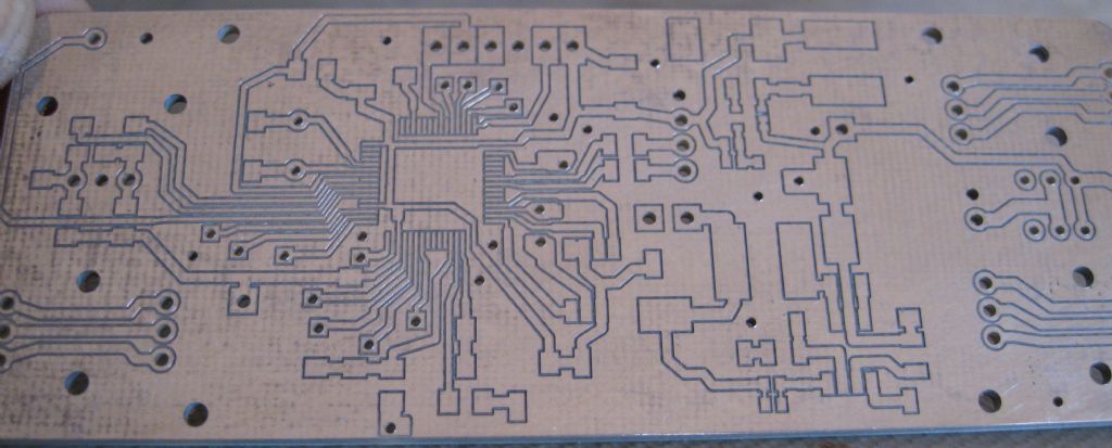
                            This PCB was made using the techniques described in my rather long post above, with freely available software as mentioned. The board is 160mm x 100mm and took about 2 hours to design, and an hour to mill – total cost = Board + zero.

                            I notice in the original post, John mentioned production of 'isolation routing' – I take this to mean that instead of etching (or routing) tracks as in the 'traditional' type of PCB, usually involving removal of relatively large amounts of copper, isolation routing simply removes a thin 'track' of copper between conductors – as per my photo below.

                            In this case, I had no necessity to make tracks the same width, or 'symmetrical', but this can easily be done using LibreOffice Draw.

                            I have never been able to find any available software which can be used to design this type of board, despite playing with the software mentioned in this thread, and others (but I guess it may exist somewherequestion). This was one reason I went the route I did, to avoid having to remove large copper areas – particularly noxious if you do it using old-fashioned etching methods, and harder (but not impossible) if you use a router.

                            Sorry about the quality – never was any good with a camerasad

                            An

                            2023-01-16-193703.jpg

                            #629770
                            duncan webster 1
                            Participant
                              @duncanwebster1

                              Ian,

                              The only time I got pcb from China I finished up paying carriage, tax and a handling charge, which took the cost of the boards from less than £10 to nearly £50. The supplier wouldn't send them China Post. If you get away without this daylight robbery please let us know. I didn't mind the tax and carriage, but the £18 handling was just a rip off. Still cheaper than I could get them in UK.

                              #629785
                              Martin Kyte
                              Participant
                                @martinkyte99762

                                I suggest you persevere with KiCad. Upgrading makes sure you have the latest libraries and generating your own is not as hard as you think. Follow a YouTube tutorial to get the general idea and you will pick it up in an hour or so.

                                regards Martin

                                #629788
                                IanT
                                Participant
                                  @iant

                                  Hi Duncan,

                                  Well these latest boards cost $9.32 for Qty 5, plus $6.35 for shipping, plus $3.06 Custom & Taxes – so a total of $18.76. I paid using PayPal and the cost in Sterling came out at £16.58 – or £3.32 a board.

                                  The finished product is fully tested, screen printed etc – it's as good as any commercial product (it is a commercial product in fact) and certainly far better than I could do myself (even assuming I had time to learn to do so). This route/method may not suit every application (such as An Os' ) but I know other people who use JLCPCB and they are also happy customers.

                                  Regards,


                                  IanT

                                  Edited By IanT on 17/01/2023 09:28:19

                                  #629793
                                  Howi
                                  Participant
                                    @howi

                                    For those still ussing veroboard – WHY!

                                    There are a number of alternatives available that are much better suited to todays electronics.

                                    Various sized boards in fibreglass with the standard hole spacing and plated dots at the hole positions.

                                    Point to point wiring is then done with a wiring pen (mine is nearly 40 years old, bought when TTL was all the rage.

                                    Spools of insulated wire are available in multiple colours and this method is ideal for prototypes where a one off board is not worth the time or cost of poroducing a PCB.

                                    The wire used needs a slightly hgher temperature than normal to burn off the insulation coating, a (variable) temp controlled iron costs very little these days.

                                    With this method you can layout your board how you like without having to think about where the tracks go.

                                    #629803
                                    Tony Jeffree
                                    Participant
                                      @tonyjeffree56510

                                      It's a long time since I used it, but the last PCB layout package I used was "Easy-PC". I seem to remember that it was (as the name implies) fairly easy to use.

                                      #629819
                                      Anonymous
                                        Posted by Tony Jeffree on 17/01/2023 10:33:20:

                                        …PCB layout package I used was "Easy-PC".

                                        I use Easy-PC, good value for money, but even the cut down versions are probably a bit expensive for occasional hobby use. I use it professionally, mostly for 4 and 6 layer boards, which are largely surface mount. It has some limitations but these wouldn't be a problem for the hobbyist.

                                        There are extensive libraries available for Easy-PC, but I prefer to make my own symbols, PCB footprints and components as it allows me to fine tune for schematic capture, PCB layout and manufacture.

                                        I've used autorouters ranging from free to hundreds of thousands of pounds. I'm not overly impressed. Cheaper ones often didn't work and expensive ones leave a mess. The circuit board is an integral part of the circuit so I prefer to layout interactively. With push and shove routers it is pretty quick, although Easy-PC isn't at that level yet!

                                        It's been years since I used Veroboard. I used to do a lot of prototyping with wire-wrap, and there used to be a system by Vero called Speedwire? Basically each pin had slots underneath and you pushed the wire in with a pen and moved on to the next connection. The pin cut into the wire to make contact. Very good for analogue, but expensive.

                                        If I do prototype these days it is always dead bug. I don't prototype complete curcuits, just key analogue sections so dead bug is fine.

                                        Andrew

                                        #629826
                                        Joseph Noci 1
                                        Participant
                                          @josephnoci1

                                          As Martin suggested, do persevere with Kicad – it is not bad at all.

                                          Your last point in the list was – free in possible – with that comes some effort on the users part!

                                          I use Seetrax's Ranger XL – only cause I have used it since 1998/Windows 95.. Now full 64bit/Win10/11 etc – Very good and quick to learn. – 30day free to test, versions that allow 100,300 and 500pins are 200, 300 and 750 pounds. Full version 2.2k pounds

                                          Then I use flatcam to take gerber to Gcode – open source and probably the best around, even in the pay world.

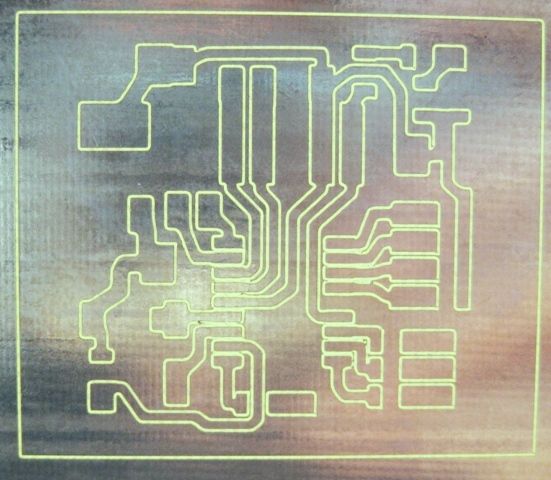
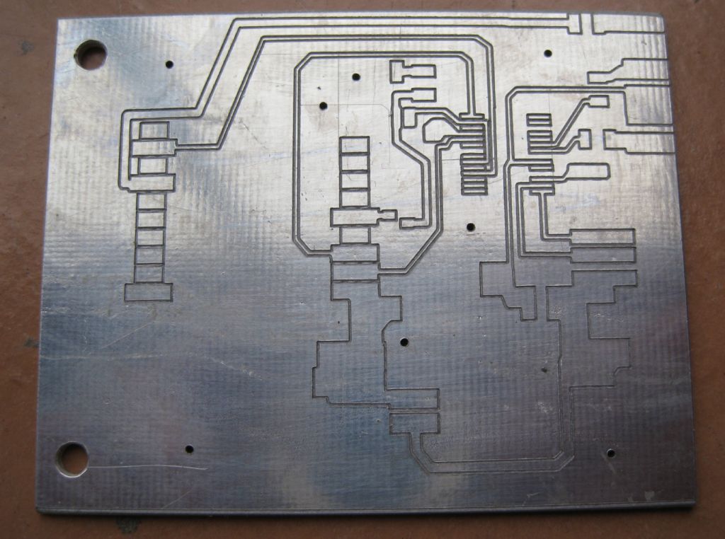
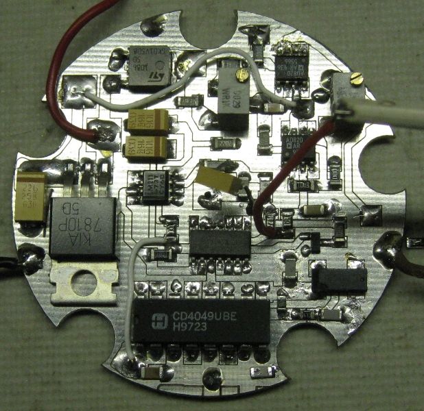
                                          pcb21.jpg

                                          routed pcb 0.5mm pin space.jpg

                                          vhf_rx_control panel.jpg

                                          sens pcb1.jpg

                                          Joe

                                          #629878
                                          Alan Wood 4
                                          Participant
                                            @alanwood4

                                            I would worry that there is no such things as a simple PCB design package unless your need is just for single copper layer PCB designs. Once it gets beyond a single copper layer, unless you are using the package on a regular basis you will find you spend a lot of unproductive time trying to 'remember how you did it last time'.

                                            That being said, Fusion 360 includes an Electronic module that is a fully fledged PCB design package. This has evolved from Autodesk's Eagle product. It has full integration within the Fusion CAD and CAM modules. This allows you to produce very complex PCB designs together with the associated enclosure, Gerber manufacturing files, CAM etc all within one application. It has extensive electronic library as standard and access to third party libraries either as a direct download or using tools such as Library Loader.

                                            In passing, Fusion 360 is currently on a 30% discount for a 1 year licence (~GBP357) but is also free for private individuals albeit with restrictions as regularly debated elsewhere on this forum. (I have no affiliation to Autodesk but admit to being an enthusiastic F360 licenced user bewildered by the value for money that the integrated product offers).

                                            Like Joseph I also use FlatCAM to convert the Gerber files to GCode for CNC milling the prototype board. FlatCAM is a powerful manipulator of PCB manufacturing information.

                                            Alan

                                            #629888
                                            duncan webster 1
                                            Participant
                                              @duncanwebster1
                                              Posted by IanT on 17/01/2023 09:27:48:

                                              Hi Duncan,

                                              Well these latest boards cost $9.32 for Qty 5, plus $6.35 for shipping, plus $3.06 Custom & Taxes – so a total of $18.76. I paid using PayPal and the cost in Sterling came out at £16.58 – or £3.32 a board.

                                              The finished product is fully tested, screen printed etc – it's as good as any commercial product (it is a commercial product in fact) and certainly far better than I could do myself (even assuming I had time to learn to do so). This route/method may not suit every application (such as An Os' ) but I know other people who use JLCPCB and they are also happy customers.

                                              Regards,

                                              IanT

                                              Edited By IanT on 17/01/2023 09:28:19

                                              Thanks, a bit more googling suggests that JLCPCB have got themselves VAT registered and so they charge vat, not the courier, hence no handling charge. I wonder if HMRC has any way of checking? Anyway, if I ever want more boards I know where to go

                                              #629891
                                              Peter Bell
                                              Participant
                                                @peterbell11509

                                                Last batch of 10 boards (double sided) I got from pcbway cost a total of $9.04 including Global Economy Shipping which took a couple of weeks to get them here with no further charges.

                                                Cost seems very reasonable if the boards are less than 100mm x 100mm

                                                Peter

                                                #629903
                                                Andy Stopford
                                                Participant
                                                  @andystopford50521

                                                  I've tried various but overall found KiCAD the best – one source of confusion though is inadvertently following a tutorial for an older version – they've changed it quite a lot.

                                                  For PCB fab, I've used Elecrow (https://www.elecrow.com/pcb-manufacturing.html), they're pretty quick and the prices and quality are good.

                                                  #629906
                                                  Huub
                                                  Participant
                                                    @huub

                                                    I use the Eagle (free version) for 10+ years and make my PCB's using the toner transfer method. I can't/want wait until a PCB arrives from China and I really like making my own stuff.

                                                    Extending the library in Eagle is "easy" if you know how to do it. I expect this applies to all schematic packages. For eagle there are also a lot of public libraries.

                                                    I have tried Kikad because it is open source but it couldn't get along with it, so I stick with Eagle. I am sure, that if I spend more time learning Kikad it will do the job.

                                                    I am going to build a dedicated router to make my PCB's. If PCB milling is your goal, you should select a package (probably a combination of packages) that can do this. Check youtube to find out how complicated it is before deciding what to use and take the time to learn it because, like all CAD/CAM software it takes some effort to learn.

                                                    #629915
                                                    Huub
                                                    Participant
                                                      @huub

                                                      I am going to use the method shown in this video. It uses Eagle and Flatcam.

                                                      PCB milling using Eagle and Flatcam

                                                    Viewing 25 posts - 1 through 25 (of 34 total)
                                                    • Please log in to reply to this topic. Registering is free and easy using the links on the menu at the top of this page.

                                                    Advert

                                                    Latest Replies

                                                    Viewing 25 topics - 1 through 25 (of 25 total)
                                                    Viewing 25 topics - 1 through 25 (of 25 total)

                                                    View full reply list.

                                                    Advert

                                                    Newsletter Sign-up