Sieg C1 lathe autofeed and screw cutting

Advert

Sieg C1 lathe autofeed and screw cutting

Home Forums Beginners questions Sieg C1 lathe autofeed and screw cutting

Viewing 19 posts - 1 through 19 (of 19 total)
  • Author
    Posts
  • #10524
    Rob Athome
    Participant
      @robathome64479

      Sieg C1 lathe autofeed and screw cutting

      Advert
      #504937
      Rob Athome
      Participant
        @robathome64479

        Hello,

        I have been asked if I can help a friend who has a Sieg C1 lathe. He wants to start using it after it has sat in the box ( crate? ) for a good number of years.

        Two things he asked about were single point threading and using the auto feed to produce a good surface finish on the material which will be aluminium or brass.

        AFAIK the C1 lathe has gearing from the main spindle to the leadscrew via a on/off clutch switch so for creating a good finish it is simply a question of engaging the function and letting the machine get on with it. How do you use this function when machining upto a shoulder ? Same goes for threading – if you want to put an M6 thread on the end of a shaft down to a shoulder.

        As there doesn't appear to be a threading dial I assume it is a case of using the reversing switch to get back to the start for subsequent passes.

        Thanks for any info.

        Rob

        #505038
        Howard Lewis
        Participant
          @howardlewis46836

          It is unlikely that there will be a clutch, as such, between mandrel and Leadscrew. More likely a handle that operates the tumbler reverse to allow the feed to be engaged, for Forward, Neutral, or Reverse.

          The technique for machining up to shoulder is to have fantastically quick reactions to open the half nuts, just before the tool hits the shoulder!.

          The practical and sensible alternative is to stop the machine just before the shoulder and then rotate the Mandrel by hand, either pulling the chuck round by hand, or using a mandrel handle.to bring the tool upto the shoulder, stopping JUST short of it.

          Your friend could spend his time well, initially, by making a Mandrel Handle.

          It could save him a lot of broken tools and scrapped workpieces.

          For a fine feed, with the aim of getting a good surface finish, the Leadscrew needs to be geared down so that it rotates as slowly as possible compared to the chuck. If it needs to be said, a small radius on the nose of the tool will improve surface finish.

          The C2 and C3 mini lathes include two 20T gears and 2 x 80T gear, among their changewheld, so a 16:1 reduction is available Probably the C1 does as well.

          With a 1.5 mm pitch leadscrew, this will give a feed rate of 0.09375 mm per rev ( 0.00369" per rev in old money)

          If the lathe is Imperial, the Leadscrew is likely to be either 8 tpi or 16 tpi.

          With a 16 tpi leadscrew this will give a feed rate of 0.00391" per rev.

          For screw cutting, the changewheels are selected to give the required ratio between Spindle and Leadscrew

          So for a 0.5 mm pitch thread, with a 1.5 mm pitch Leadscrew tjhte ratio would need to be 3:1. Probably using a 20T on the Mandrel, and driving via an Idler, to a 60T on the Leadscrew.

          To cut a 1 mm pitch thread the ratio would need to be 1.5:1 so probably a 40T driver to a 60T on the Leadscrew , with an Idler to fill the gap between the gears.

          If your friend is unsure, he needs to buy a couple of books, for a deeper explanation and examples of set ups.

          Martin Cleeve's "Screwcutting in the Lathe" which is No. 3 in the Workshop Practice Series, and Brian Wood's "Gearing of Lathes for Screwcutting" The latter gives table of changewheel set up for a number of lathe, so that probably no calculations would be needed, just set up according to the tables for your particular lathe, or one with a Leadscrew of the same pitch.

          Obviously if cutting an Imperial pitch thread on a Metric lathe, or vice versa, ideally a 127T gear would be needed, but a 63T gear will produce threads with acceptable pitch errors,being a it is low powered, so shallow depths of cut will be the order of the day.

          The manual for the C2 or C3 regards 0.010" (0.254 mm ) as a roughing cut, although many exceed that figure without problems.

          HTH

          Howard

          #505047
          Rob Athome
          Participant
            @robathome64479

            Hello Howard,

            Many thanks for the detailed reply. The Sieg C1 has a mechanical lever to engage the autofeed and a separate switch to set the motor rotation to 'forward' or 'reverse'. There aren't any half nuts as in most mini lathes to dis-engage the saddle from the leadscrew. I checked out a parts diagram/listing for the C1 and what they refer to as a clutch is more of a forked coupling.

            You are quite correct about a radius on the tool being sensible – I use this method myself for finishing cuts – it works well on brass parts but no quite so well on aluminium etc in my experience.

            The manual for the C1 that I tracked down indicates a feed rate of 0.025 or 0.05mm per chuck revolution depending on which of the standard gears you have bolted on. There is also an extra set of gears available that whilst mainly intended to give metric thread pitches of 0.5 to 1.5mm can also function to make a coarser auto feed rate.

            I suspect I should find out how much threading he wants to do and consider if just a tailstock die holder may be better suited.

            Thanks again.

            Rob

            #505088
            Ronald Morrison
            Participant
              @ronaldmorrison29248

              The fact that the lathe motor can be run in reverse makes threading to a shoulder for imperial threads much easier. With the motor running in reverse use a boring bar with a thread cutting end on the backside of the stock , bring it to the shoulder, then engage the "half nut'. Now you cut threads away from the shoulder so you don't have to have lightning reflexes. Making a stop for the carriage lets you set the starting point so the tool never hits the shoulder.

              #506889
              woody1
              Participant
                @woody1

                Threading can sometimes turn into a "bain of your life thing", if I can get away with a die on smaller diameters happy days. On larger diameters I have found roughing with a single point then finish with the die, a far better operation all round, in both speed and finish. My machine is a cl300m I don't know how that compares to a C1?

                Woody.

                #506893
                Rob Athome
                Participant
                  @robathome64479

                  Thanks Woody and Ronald for replying.

                  Rob

                  #506923
                  not done it yet
                  Participant
                    @notdoneityet
                    Posted by woody1 on 11/11/2020 21:38:24:

                    Threading can sometimes turn into a "bain of your life thing", if I can get away with a die on smaller diameters happy days. On larger diameters I have found roughing with a single point then finish with the die, a far better operation all round, in both speed and finish. My machine is a cl300m I don't know how that compares to a C1?

                    Woody.

                    In addition to the above points, threading larger diameters (particularly of coarse threads) can be very hard work if using a die. Also single pointing assures the thread is properly aligned with the material being cut, before finishing with a die.

                    #506931
                    HOWARDT
                    Participant
                      @howardt

                      You could leave the lead screw and nuts engaged and rotate the spindle by hand. Whilst time consuming with small depth of cuts it is one way to cut to a consistent point. Like most I thread with split dies, most of mine are small, M2 etc but I do go up to M16. Some odd pitches will require some additional gears which can be easily obtained.

                      #507086
                      woody1
                      Participant
                        @woody1
                        Posted by not done it yet on 12/11/2020 07:00:37:

                        Posted by woody1 on 11/11/2020 21:38:24:

                        Threading can sometimes turn into a "bain of your life thing", if I can get away with a die on smaller diameters happy days. On larger diameters I have found roughing with a single point then finish with the die, a far better operation all round, in both speed and finish. My machine is a cl300m I don't know how that compares to a C1?

                        Woody.

                        In addition to the above points, threading larger diameters (particularly of coarse threads) can be very hard work if using a die. Also single pointing assures the thread is properly aligned with the material being cut, before finishing with a die.

                        Tell me about it, I machined an entire air rifle block with a thread of 1/2" X 14nps so quite course. Left this until last got lazy didn't rough enough and the tap went in not even remotely perpendicular. 2 days of work lost. It happens but learn from your mistakes and all thatcrying

                        #587121
                        Alf Beharie
                        Participant
                          @alfbeharie22737

                          Hi, I'm new here. I own an Axminster Sieg C1 Micro Lathe, which I bought a couple of months ago on ebay used for £210, and I am currently collecting all the tools and accessories for it I can find, as it literally came with nothing but the tool post and a dead centre in the tailstock…It didn't even have a clutch selector knob fitted! (Luckily I was able to get a new one from Arc Euro Trading).

                          I would like to be able to cut threads with it that are larger than possible with a floating tailstock die or tap holder set. ( I have an MT1 set on the way which comes with three different size die holders) That would of course require a change gear set.

                          In researching C1 change gears I discovered they are available individually from Ar Euro Trading but at about £8.35 each, inc VAT, so they are too expensive for me right now.

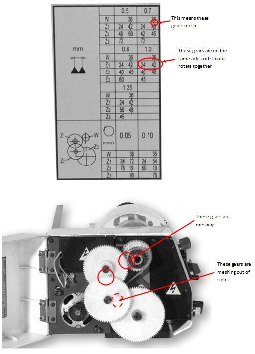
                          The C1 manual shows a total of seven change gears but the change gear table diagram, on page 23 of the manual, makes absolutely no sense at all to me…I can't work out which ones to use or in what combination from looking at the table.

                          I subsequently discovered that I can get a change gear set for the C1 on (Deleted see CofC) with a nine gears, for under £25 too. But as the table only covers up to the standard seven change gears, even if I could make head or tail of it I would still have two gears that would not be on it the table!

                          Any help making sense of the change gear diagram would be much appreciated.

                          Alf.

                          Edited By JasonB on 25/02/2022 06:54:20

                          #587165
                          Martin Connelly
                          Participant
                            @martinconnelly55370

                            sieg change gears.jpg

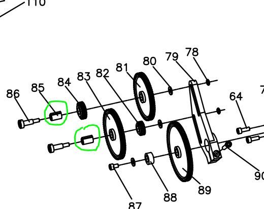
                            The illustration from the manual shows the gear train set up for fine feed of 0.05 mm/rev. There is a means of adjusting the position of Z1 and Z2 to obtain the correct gear meshing, item 79 support plate, usually referred to as a banjo due to its shape on a lot of lathes.

                            Martin C

                            #587232
                            Howard Lewis
                            Participant
                              @howardlewis46836

                              basically, you select a train of gears to give am ratio between the chuck and the Leadscrew.

                              So, if the lathe has a Leadscrew with a 1.5 mm pitch.

                              To cut a 1.5 mm pitch thread, the gears should give a ration of 1:1, and ensure that the Saddle moves towards the Headstock, for a Right Hand Thread.

                              For a 1 mm pitch thread the ratio should 1.5 :1, ie the Leadscrew rotates slower than the chuck, For this you might have a 30 T driver with an Idler (which will not affect the overall ratio, but ensure correct direction of rotation ) with a 45T on the Leadscrew.

                              For a pitch of 0.75 mm the Leadscrew needs to rotate half as fact the chuck, so possibly a 40T driver, Idler, and 80T on the Leadscrew.

                              For a 0.5 mm pitch, the Leadscrew rotates at one third of the speed of the chuck, so possibly a 20driver with a 60T on the Leadscrew

                              To cut Imperial threads, the same logic applies, but the train needs to incorporate a 63T gear (On the Leadscrew )which will give the Imperia thread, but with a small error (A 127T would, give an exact translation from metric to Imperial, or vice versa; hence a 63T introduces a small error in some cases. Sometimes this can be overcome by using gears which do not give an exact ratio to the Leadscrew pitch.

                              Brian Wood's book "Gearing of lathes for Screwcutting" gives examples

                              Another book is Martin Cleefe's " Screwcutting in the Lathe" which is No 3 in the Workshop Practice Series..

                              Using the Leadscrew to give a fine feed, involves setting up the largest possible ratio between chuck and Leadscew. On mini lathes, with a 1.5 mm pitch Leadscrew, this is usually a 20T driving a 80 /20 compund idler, which drives another 80T on the Leadscrew. This will give a feed of 0.09375 mm per rev.

                              In essence, for a finishing cut, you are cutting a very fine thread with a pitch of 0.09375 mm but only ,say, 0.025mm deep.

                              HTH

                              Howard

                              #607824
                              Willem Houweling
                              Participant
                                @willemhouweling20946

                                Hallo you all model engineers I 'm new here and from the Netherlands

                                Just but me a Sieg C1 to replace the old Unimat 3.

                                I 've also got a problem with the threading gears as well the table , see above , states when going for the 1.0 metric thread that gears 40 and 48 are connected on the same axle HOW? thes are lose gears so the 48 will be driven by the 42 gear but the 40 will not since they are not connected? can any one explain The manual cant and I couldn't find special bolts etc on internet . grtz from Holland Willem

                                #607854
                                JasonB
                                Moderator
                                  @jasonb

                                  I thought that the pairs of gears fit onto sleeves that have a key which fits the keyway in the gears so that they rotate as one.

                                  c1 sleeve.jpg

                                  c1 gears.jpg

                                  Edited By JasonB on 30/07/2022 07:04:06

                                  #607857
                                  Howard Lewis
                                  Participant
                                    @howardlewis46836

                                    If you are cutting a thread up to a shoulder, it may be safer to rotate the chuck, by using a mandrel handle.

                                    I made one for my C3. Anyone who wants a picture of it, and the components.can PM me with an E mail address

                                    There have been various other ways of clamping the handle into the spindle, some probaly easier than the method that i used.

                                    For a finest feed rate on a C3, the set up is Spindle 20T, Idler 80T/20T, Leadscrew 80T

                                    For various standard pitches, if taps and Dies are not being used, see the Operator Manual.for changewheel set ups.

                                    If that is not available, Brian Wood's book "Gearing of lathes for Screwcutting" gives tables for mini lathes (And others ) with Imperial or Metric Leadscrews.. To cut Imperial on a Metric machine, or vice versa, a 63T gear will be necessary, which will produce slight errors on some pitches. Probably of little consequence unless long threads are being cut. (And I would not expect a mini or micro lathe to be used to cut long M12 or larger threads!if .

                                    When using Taps and Dies, it is worth using a Sliding Die holder in the Tailstock. This greatly reduces the load on the newly cut thread, since the Tailstock is not being dragged along the bed..

                                    I made a Sliding Tap Holder, for the same reason. Alternatively, the Tap can be located by a male or female Centre in the Tailstock, and the tap rotated by hand, with the Tailstock barrel being advanced at regular intervals to steady the Tap.

                                    Manual rotation may be slower than power feed, but reduces the risk of damaging or stripping the thread that is being cut.

                                    Howard

                                    #607858
                                    JasonB
                                    Moderator
                                      @jasonb

                                      Old thread alert, best just answer the recent question

                                      #609201
                                      Nigel Graham 2
                                      Participant
                                        @nigelgraham2

                                        I'd go with the mandrel handle and hand rotation for many such applications if you use only a relatively simple lathe.

                                        A point though that seems not stressed. If you disengage the change-wheel drive or half-nuts (if the lathe has them) at any point in mid-threading, you do need ensure re-engaging at exactly the right point in the right direction for the next pass. If you miss, it you ruin the thread!

                                        Manually winding the lathe back and forth may be rather tedious if you are making lots of shouldered fittings, or indeed studs, but at least is safe because the drive stays engaged.

                                        (Unless you fail to withdraw the tool enough for its return trip… Yes, I have done that!).

                                        .

                                        I have often used the tailstock centre as a tap guide as Howard describes. A bit of centre-drilled rod held in the drill-chuck will handle centre-pointed taps. I did though buy a spring-centre for taps, for use on the lathe, mill or bench-drill – it's proved a worthwhile investment. They are not very difficult to make and sometimes appear as exercises in the self-teaching literature, but sometimes I prefer to make things, not things to make things! The point is reversible to accommodate either centre-drilled or centre-pointed, taps.

                                        .

                                        On using the lathe in reverse and a tool behind the work: fine but be careful if the chuck is screwed onto the mandrel. I think many of the "mini" lathes have their chucks on studs and nuts, so free of that hazard.

                                        #609256
                                        Howard Lewis
                                        Participant
                                          @howardlewis46836

                                          Nigel mentions winding the Saddle to and fro, or rotating the chuck in the opposite direction..

                                          DON'T forget to wind it back far enough that when you come forward again, all the backlash is taken out!

                                          (That comment applies whether screwcutting or for any machining.)

                                          Howard

                                        Viewing 19 posts - 1 through 19 (of 19 total)
                                        • Please log in to reply to this topic. Registering is free and easy using the links on the menu at the top of this page.

                                        Advert

                                        Latest Replies

                                        Home Forums Beginners questions Topics

                                        Viewing 25 topics - 1 through 25 (of 25 total)
                                        Viewing 25 topics - 1 through 25 (of 25 total)

                                        View full reply list.

                                        Advert

                                        Newsletter Sign-up