Short technique, set-up and problem solving articles for MEW

Advert

Short technique, set-up and problem solving articles for MEW

Home Forums Model Engineer & Workshop Short technique, set-up and problem solving articles for MEW

Viewing 18 posts - 1 through 18 (of 18 total)
  • Author
    Posts
  • #388184
    Clive Foster
    Participant
      @clivefoster55965

      Neil has often said that he could use more short articles in MEW. Articles dealing with isolated tricky machining or set-up problems encountered as part of larger job could be about the right size and possibly of some interest to readers.

      I'm thinking of the sort of superficially simple job that actually turns out to need a fair bit of thinking from more or less first principles to fit it onto your equipment and get done right. Something that would have gone ten times easier if you had an example from someone else to either follow, modify or at least draw inspiration from. Most of us have been there on more than a few occasions.

      A job I'm about to set-up and start cutting metal on got me thinking about things from the perspective of the inexperienced worker.

      The task is to cut a pair of truncated Vee form index slots at exactly 180° spacing to finish off a part for a Clarkson drill and tap sharpener. This component was missing on the one I bought so I had to re-engineer from scratch. Main job is of no interest being simple turning and boring but the business end of the indexing lever has tapered sides so the slots need matching tapers.

      An excellent design for a solid shake free index. Figuring out the machine settings to get an accurate taper on the sides isn't straightforward if you've not done that sort of thing before. I had but it was a long time ago! Taking all potentially reasonable combinations of work holding and cutter strategies there are probably over 20 different way of tackling the job. I figure I have kit for about 10 of them which doesn't really help. Some of the potentially reasonable approaches hide some horrible bear traps which a less experienced worker might not appreciate until too late. Due to its shape this particular part hides a couple of really sneaky traps. The sort you might get away with once or twice if the gremlins are on holiday.

      Do folk think this sort of thing would be of interest.

      Clive.

      Advert
      #38509
      Clive Foster
      Participant
        @clivefoster55965
        #388185
        peak4
        Participant
          @peak4

          Clive, yes I'm sure it would be of interest, particularly to people like me with no formal training or work experience in the field. All the gear, well lots of the gear, but no idea. blush

          Since many of my little jobs are repair/replacement of parts, I've no idea how they may originally have been made. By their very nature they are likely to be one-offs, with no book or magazine articles top provide guidance.

          I'm also curious to know which bit you're making yourself; is it the little lever detent arm above the 0-10 scale shown on the photos in this article.?

          Bill

          #388187
          John Harding
          Participant
            @johnharding75458

            YES! Milling a 90 degree V-slot is simple enough but how do you mill one with other angles and trucated bottom? The traps I found were getting it to the right width and on centre to match its mating prism.

            John

            #388220
            Clive Foster
            Participant
              @clivefoster55965

              Bill, John,

              Thanks for the encouragement. Looks like I'd better get the camera batteries charged up.

              Part I'm making is the top hat shaped collar with two notches in the brim for that lever to drop into. Need to scroll down a long way in Bills' link to find some decent pictures. A fair number of the pictures seem to show homemade versions too.

              Theoretically its just basic trigonometry to figure out the widths, offsets and rotations needed to get such slots right. In practice its very easy to get muddled up if you don't think it through carefully. I find writing down the sequence of operations first and sticking to the list helps greatly. CAD program lets you draw it out right and checks your trigonometry but do the maths first, don't rely on the CAD. Hint. Draw the cutter too if you aren't sure about compensating for its diameter when shifting after rotating.

              Clive

              #388246
              Neil Wyatt
              Moderator
                @neilwyatt

                Hi Clive,

                Yes indeed, this is exactly the sort of machining challenge hat many readers find interesting.

                Neil

                #388258
                peak4
                Participant
                  @peak4

                  Neil, please feel free to move to another thread to save disrupting this one.

                  I've often found that a good way to come up with a solution, is to chuck a few ideas in the pot and let someone else pick holes in them. So long as everyone plays fair and doesn't seek to cause or take offence, it's worked quite well amongst my various friends and acquaintances.

                  Here's one, (that I've never tried), using the basics of my own kit; lathe, V.mill, and rotary table (without any dividing plates).

                  For a photo, click on "2" on my previous link, and scroll down to the 4th photo.

                  I guess I have the advantage/disadvantage of no training on how one should approach a job.

                  The intention is to make the gizmo without needing to also make loads of extra jigs/fixtures, and minimise the maths, as not everyone is comfortable with trig tables.

                  1) Turn the top hat to size on the lathe, index the jaws of the chuck with a suitable stand off from the bed and mark off 2, 3, 4, or 6 lines at centre height using the chuck jaws to divide accurately. (3 or 4 jaw chuck according to how many slots required.)

                  2) Move chuck to rotary table, standing on edge, on V.mill

                  3) Mill slots as required, according to previously marked lines, but slightly undersized. (I couldn't easily get exactly the right angles for the sides of the slots due to lack of dividing plates, just the whole degree scales on the periphery of the table. )

                  4) Transfer back to the lathe

                  5) Grind and hone a bit of tool steel to exactly the same size/angle as the detent lever, by eye if necessary.

                  6) Use your new tool, horizontally in the lathe toolpost, again indexing the chuck jaws on the bed, in the manner of a slot cutter to plane the undersize slots to the correct profile and depth.

                  This should cover most tap, drill, or core drill flutes, but obviously not 5, 7 etc.

                  You could even try a test piece, and a bit of blue on the detent to see if you've honed the angled tool accurately.

                  No trig involved, or scope for miscounting scales on New Year's day morning. blush

                  Please feel free to pick holes in the above; that way we all learn.

                  I've just typed it quickly without fully thinking it through. (other than not using machine tools with a hangover of course angel 

                  Bill


                  Edited By peak4 on 30/12/2018 12:19:36

                  Edited By peak4 on 30/12/2018 12:33:30

                  #388265
                  Bazyle
                  Participant
                    @bazyle

                    I guess you should start by "how to measure the included angle of a little detent". please.

                    edit: and the width, without special tools like digital angle gauges.

                    Edited By Bazyle on 30/12/2018 12:48:14

                    #388269
                    Clive Foster
                    Participant
                      @clivefoster55965

                      Bill

                      Nice try. About where I started before realising just how many ways of getting it wrong there were. Actually this turned out to be one of those time when doing it the right way is actually quicker and easier than diving in knife'n fork style. If you don't count the (painful) time taken in figuring out the right way of course.

                      Bazyle

                      Without special tools eh! I guess that means a gear tooth vernier is out then. Pity, been looking for a good excuse to use mine ever since I got it over 30 years ago.

                      Never mind the poor-boys' bevel protractor substitute will work just fine. Looks like I've got to take the indexing lever off to photograph the set-up even though careful use of a vernier with good knife edge jaws did it for me.

                      Clive.

                      #388323
                      Anonymous

                        The first question should be what angular accuracy is required of the part; then one can put together a machining sequence to meet that requirement.

                        Andrew

                        #388329
                        Ian Skeldon 2
                        Participant
                          @ianskeldon2

                          A couple of very simple tips for absolute beginers.

                          On my bigger lathe I have a QCTP and a conventional TP on the smaller lathe.

                          TIP : My preferred method of setting the tool height is to simply face the work piece, when the small nub has gone tool is at correct height.

                          TIP : I have lots of cheap feeler guage fingers to allow me to get the tool bang on, I can very quickly shim up a tool to get it right using these for final adjustment.

                          I have made brass GIB strips for the older lathe to replace the worn steel ones, the carriage is now slop free but movable.

                          Ian

                          #388348
                          Clive Foster
                          Participant
                            @clivefoster55965

                            Bazyle.

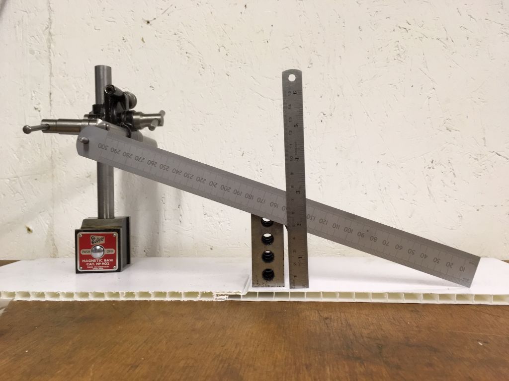
                            Had a spare half hour before tea so I quickly mocked up the Poor Boys Bevel Protractor device for measuring smallish taper angles. Basically two rulers. One supported at the end so it lies alongside the taper to be measured and one held vertically. Make two vertical measurements a suitable distance apart. Subtract small one from larger and divide by the separation measured along the sloping ruler. Result is the sine of the taper angle.

                            If you are careful and have a decent separation between measurements the accuracy is more than good enough for many purposes.

                            I used a magnetic base and one of my "ruff" 1-2-3 blocks for the picture as being immediately to hand but that's absolutely the high end sophisticated version. Especially as there is a weak bar magnet on the 1-2-3 block holding the rulers stable.

                            poor boys bevel protractor r.jpeg

                            Does that meet the without special tools criteria?

                            Clive.

                            #388356
                            pgk pgk
                            Participant
                              @pgkpgk17461

                              I just assumed you guys would just cut the slot to width at depth and file the sides to scribe lines…?

                              ..of course if your filing is like mine then without file guides it'd look like my dog has been chewing at it..

                              pgk

                              #388601
                              Ian Skeldon 2
                              Participant
                                @ianskeldon2

                                Crikey, is that the some old horse etc, etc. That takes me back some 40 odd years. Has anyone used the cheap (around £20) chinese digital angle guages? if so are they accurate?

                                Ian

                                #388603
                                Bazyle
                                Participant
                                  @bazyle

                                  That's rather neat Clive. I like the way you hung the rule using it's hole. Was in Lidl today and they have digital angle gauges at a tenner I think but I prefer things that don't use batteries.

                                  #388614
                                  bricky
                                  Participant
                                    @bricky

                                    The digital angle gauge comes into it's own when you need hands free and one can measure angles with the use of paralells that are not possible with a protractor.

                                    Frank

                                    #388760
                                    Ian Skeldon 2
                                    Participant
                                      @ianskeldon2

                                      I don't think you can go wrong for a tenner as long as it's accurate enough for the intended use, I will have to take a look around for a Lidel, thanks Bazyle.

                                      #388771
                                      Clive Foster
                                      Participant
                                        @clivefoster55965

                                        As Ian says the Poor Boys Bevel Protractor is a very old idea. Probably the grizzled old machinist who showed it to Ian 40 years ago was similarly shown it 40 years further back by a grizzled old …. etc, etc. Odds are that the guys who built the pyramids had a version in their tool kits. Almost certainly more names and variations than could be conveniently counted. Understandably being an ad hoc device made from what you have to hand. My father showed it to me using a pair of folding carpenters rules back when I was hardly tall enough to see over the table.

                                        Can be decently accurate. Consider measuring 30° with nominal 100 mm between vertical measurements. For practical purposes ± 0.5 mm on both spacing and verticals corresponds to ± 0.3 degrees. Not too shabby for an improvised device. Odds are that your errors will be in same direction so probably rather better. Using the depth probe on a vernier is objectively getting silly but better still. After all the thing is basically a sine bar.

                                        One great, and often overlooked advantage of old style analogue instrumentation is that you are largely in control of accuracy. Within reason. You know if quick and dirty will do or if its time to be really careful and do the best you can. Usually possible to figure out errors if need be and work around them. Digital instruments give you what they give you, quickly and repeatably. Which is great but when you get close to the limits you don't know what you have.

                                        In my view the inexpensive angle gauges, Wixley et al, are within 0.5° devices if you just plonk them on. Takes a bit more care to get accuracy and advertised resolution to match. Considering that they work by measuring the movement of a tiddly little pendulum the performance is remarkable. Especially given the very low cost. 0.1° is very little. Almost seems unreasonable that such a small pendulum can move freely and repeatably over such a tiny distance. The bigger and heavier pendulum in my Cowley level does no better, and frequently worse.

                                        Digital does tend to destroy perception of the real size of things. A number on a display is just a number so its very easy to talk about impressive numbers without realising what they mean. Randall Munroe has a good take on this, albeit getting bigger rather than smaller, **LINK** .

                                        The battery life issue becomes very pertinent for rarely used instruments. I have two different types of combination square and a good bevel protractor. Which I wouldn't be without. But I doubt if all three got used more than 10 or 12 times between them last year for angle gauge type measurements. If even that. Probably not an untypical year. So very good chance that an electronic one would have a flat battery. YMMD.

                                        Clive.

                                        Edited By Clive Foster on 01/01/2019 22:30:52

                                        Edited By Clive Foster on 01/01/2019 22:31:39

                                      Viewing 18 posts - 1 through 18 (of 18 total)
                                      • Please log in to reply to this topic. Registering is free and easy using the links on the menu at the top of this page.

                                      Advert

                                      Latest Replies

                                      Viewing 25 topics - 1 through 25 (of 25 total)
                                      Viewing 25 topics - 1 through 25 (of 25 total)

                                      View full reply list.

                                      Advert

                                      Newsletter Sign-up