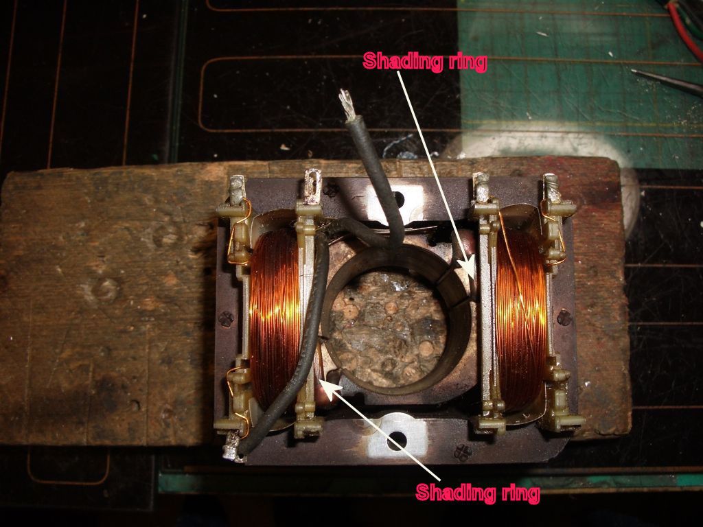
shaded pole motor

Advert

shaded pole motor

Home Forums Electronics in the Workshop shaded pole motor

Viewing 25 posts - 1 through 25 (of 27 total)
  • Author
    Posts
  • #222882
    Lynne
    Participant
      @lynne

      I have an extractor fan motor (not working) where one shaded ring is wired in parallel with the stator windings. An internet search of wiring diagrams does'nt show this, but there are so many I may have missed it. Is this wiring arrangement unusual. I would be interested to know a bit more about it.

      Regards Lynne

      Advert
      #31822
      Lynne
      Participant
        @lynne
        #222895
        john fletcher 1
        Participant
          @johnfletcher1

          Shaded pole motors are cheap as chips. Lots of washing machine pumps and fan heater and as you say extractor fans have shaded pole motors. They have poor starting torque. On some it is possible to dismantle the motor and reassemble it so that it run in the reverse direction, not all though. Usually the shaded pole is a piece of copper (ring) inserted in the main laminations.John

          #222900
          John Haine
          Participant
            @johnhaine32865

            Wikipedia tells you all that is probably worth knowing:

            **LINK**

            If the shaded pole winding isn't just a shorted turn, then it may be connected to things like capacitors in various ways to control e.g. starting torque; of there may be two that can be shorted (one or the other) to reverse the motor. I don't think they would be connected in parallel with the stator winding – as they have much lower inductance this would just blow the fuse!

            #222907
            KWIL
            Participant
              @kwil

              I have never seen a shaded pole motor where the shading ring is connected to anything else. Try removing any linking wires so that you are left with the coil only connectd to the power.

              Reversal can be achieved where you can disemble the motor completely and invert the laminated stator block.

              #222987
              Lynne
              Participant
                @lynne

                Thanks to all who have responded to my post. Having looked again one lead is is attached to a stator coil, however

                the other lead is not , I had thought that there was a link from where the other wire of the coil was soldered, to the tag where the other lead shaded ring was attached , and there is'nt. deteriorating eyesight, age related that is my excuse. There was once a speed control system consisting of potentiometer triac resistor and capacitor, which overheated in a serious fashion, burnt out infact. I am not into electronics sufficiently to put together a replacement.. The resistance through the stator windings is 8 ohms, which seems very low.

                It is going to be an interesting exercise to find a replacement which is dimensionally similar. The extractor assembly is German , as are the rest of the kitchen units, and fitted over 25 years ago

                Regards, Lynne

                #223009
                KWIL
                Participant
                  @kwil

                  If product is German in origin, start by looking at Papst motors as a starting point.

                  #223138
                  Lynne
                  Participant
                    @lynne

                    KWIL, Thanks for the lead.

                    #223153
                    Colin Whittaker
                    Participant
                      @colinwhittaker20544

                      A shaded pole motor is an induction motor. Induction motors use a rotating magnetic field from the stator to drag the rotor around. Once it starts spinning an induction motor no longer needs a rotating field.

                      The simplest induction motor is the three phase where the rotating magnetic field comes from three or six windings and the 120 degree phase difference between phases.

                      Unfortunately the majority of us don't have three phases and some slight of hand is needed to make an induction motor work with a single phase.

                      The most common solution is to use one set of windings connected to the AC supply and a second set of windings connected via a phase shifting capacitor. Usually the capacitor is used just for starting and then disconnected with a centrifugal switch but sometimes the capacitor is left permanently connected.

                      A shaded pole motor saves on the sets of windings, it only uses one. The phase change is obtained by a copper ring circling half of each pole piece. As the flux starts to increase through the pole a current is induced in the copper ring that opposes and delays the build up of flux. This causes the magnetic field to rise first in the unshaded pole and then move to the shaded pole. It's not a high torque from rest so it probably won't work for a compressor but it does find many applications such as a fan.

                      However, if you have two sets of windings then this sounds like a variation on the capacitive start motor where one winding is normal but the second has a significantly higher resistivity. This higher resistivity delays the build up of the current in this coil and therefore delivers a delayed field hence a rotating field. (But please don't call it a shaded pole motor.)

                      #223319
                      Lynne
                      Participant
                        @lynne

                        Colin, thanks for your informative response.The motor does indeed have 2 stator winding, and 2 shading rings, one of which has 2 leads from it which I now am aware was probably connected to a capacitor. There was once a speed controller which gave variable speed (not stepped) and a capacitor which had seen better days, just a sticky mess, , so I could'nt determine any values the rest of the controller had burnt out .The extractor hood assy is German, and a label on the casing states 'motor 230v, 50hz,230w.

                        I have readings through the 2 stator windings, the rotor looks ok , but how would I check?. Capacitor type and values? and wiring it in would be speculative. I would be quite pleased to have the motor run at one speed.

                        The motor has all the characteristics of a ______ from what I have seen of pictures, so what should I call it. I could come up with a few non electrical terms. Regards Lynne

                        #223323
                        John Haine
                        Participant
                          @johnhaine32865

                          Rotors are essentially solid steel and copper, if it rotates freely it is almost certainly OK.

                          As it has 2 shaded poles it will probably run quite happily without a capacitor. How are the stator windings arranged? Can you post some photos?

                          #223578
                          Lynne
                          Participant
                            @lynne

                            John, I have created an album,and there should be a photo of the motor

                            #223581
                            Martin W
                            Participant
                              @martinw

                              Just a quick thought, could that be a connection to a thermal switch/fuse that is bedded in the assembly to protect the windings/motor from overheating?

                              Martin

                              #223589
                              Nicholas Farr
                              Participant
                                @nicholasfarr14254
                                Posted by Colin Whittaker on 30/01/2016 09:09:11:

                                A shaded pole motor is an induction motor……………………………………………………………………………………………

                                (But please don't call it a shaded pole motor.)

                                Hi Colin, I beg to differ, a shading coil can be clearly seen on each pole of Lynne's motor, therefore it is a shaded pole motor.

                                Regards Nick.

                                #223590
                                Nicholas Farr
                                Participant
                                  @nicholasfarr14254
                                  Posted by John Haine on 31/01/2016 11:36:31:

                                  Rotors are essentially solid steel and copper, …………………………………………….

                                  Hi John, the majority are steel laminations and an aluminium embedded squirrel cage, but copper can also be used for the squirrel cage.

                                  Regards Nick.

                                  #223603
                                  Les Jones 1
                                  Participant
                                    @lesjones1

                                    Hi Lynne,
                                    I have never seen any connections made to the shading rings on a motor. I can not see any connections to the shading rings on the side of the motor in your photo. can you post a picture of the other side of the motor showing the connection to the shading rings. Also can you post the schematic of how the motor was originally wired. Was the capacitor you refer to just the low value capacitor (In the region of 100 nF) used in the phase angle speed controller or was it a larger value capacitor.

                                    image020216a.jpg

                                    I have copied your picture into this post so that people do not have to go to your album to see it.

                                    Les.

                                    #223609
                                    Colin Whittaker
                                    Participant
                                      @colinwhittaker20544

                                      Thanks for posting the picture.

                                      Nick, without the picture it had sounded as though there were two sets of coils. I can see now that there is just one set of coils connected in series or parallel so they both see the same phase.

                                      The shading rings will delay the field causing it to rotate anti clockwise as viewed in the picture.

                                      Lynne, I can't see any reason for a capacitor to be included unless it was for power factor correction but that seems a little over the top for a small cooling fan motor.

                                      Variable speed control? Well it will almost certainly be a variable frequency drive with some way of limiting the current as the frequency is dropped. Getting this motor to work at a fixed "semi-synchronous" speed looks achievable. Variable speed operations sounds ambitious.

                                      Nick again, I see your comment about aluminium wired squirrel cages. I had thought all squirrel cages used copper wiring to maximise the rotor volume/area available to the magnetic flux of the steel. However I see from an internet search that cast aluminium is being used. Is this common? I've never seen it and I'm frequently at the electric motor rewinders here in Phuket.

                                      Cheers, Colin

                                      P.S. I was taught electric motor theory by Prof. Eric Laithwaite. That may or may not have been an advantage when hypothesising on motors like this.

                                      #223616
                                      John Haine
                                      Participant
                                        @johnhaine32865

                                        Colin is correct, this is a basic single winding shaded pole motor where the winding is split between the two opposing pole pieces. The extra black wire is odd and if I had to guess it's an extra winding that used to generate a low voltage to do with the crude triac speed control. The two "shade" windings are entirely conventional.

                                        Lynne, I'd suggest stripping off the thick black wire and the motor should work at a single speed off the mains. No need for any capacitors or anything like that. This should get your extractor back on the road.

                                        This motor probably has quite a high resistance rotor and would qualify as a "torque motor". These run at high slip ratio and you can vary their speed by varying the winding current. Used for example as spool drives in reel-to-reel tape decks, where a low current is used when playing or recording, a higher current for fast-forward or rewind. I used to have a Magnavox deck which had two of these for the spools, plus some big resistors switched in and out to vary the torque depending on what you were doing. There was a third more conventional motor driving the capstan at constant speed.

                                        The triac control would just be working like a lamp dimmer, the capacitor probably as a phase shifting component in the gate drive. Horrid.

                                        Modern higher power induction motors use cast-in aluminium windings for their squirrel cage, but all the cheap shaded pole motors I have ever seen have their rotors made of copper rods rivetted through the laminations to copper end rings – the kind of thing that can be done in a jobbing engineering shop.

                                        Edited By John Haine on 02/02/2016 10:44:51

                                        #223644
                                        Muzzer
                                        Participant
                                          @muzzer

                                          Can't help thinking the black wires simply go to a thermal cutout buried down the side of the winding. It also looks as if the free black wire was originally soldered to the spare tag (second from left on top row). I bet if you measure between the black wires you will find an open circuit (non-resettable thermal trip blown) and if you bypass the black wires the motor will run again.

                                          Of course, even if this "fixes" the motor, the cause of the overheating may still remain. Generally the lifetime of a motor like this will be down to the bearings (not shown). Both porous bushes and ball bearings dry out with time, at which point the motor load, winding current and temperature will increase. Unless this is an impedance protected motor, you need a thermal cutout to protect against stalled or overloaded conditions. You might bypass the cutout but if you don't rejuvenate the bearings, you may simply cause a fire next week / month / year.

                                          For motors of this quality, you may be best to throw it in the skip and buy a new one. They aren't really intended to be repaired.

                                          #223803
                                          Lynne
                                          Participant
                                            @lynne

                                            Muzzer. You are correct, the free black lead did go to the tag. Your suggestion that the two were from a thermal cutout buried down the side of the windings, encouraged me to try and extract it, and it did relatively easily, together with the protective shroud. I have put a picture in my album, for as yet I have not sussed attaching pictures to my posts. However I did get a reading of 8 ohms across the two leads, and 18 ohms through the two stator windings, so what does that tell you?

                                            Reasons for overheating. The motor and cyl. type fan, were seriously gunged up with fat, despite renewing filters from time to time. It would be a shame to bin it, as the bracketry and bearings are robust, and incorporate rubber mtgs.

                                            Les. Thanks for the picture upgrade. Wish I were able to do that. No info on wiring arrangement. Capacitor value, no idea. The innards had extruded themselves from the casing, which was a sticky mess, and attempts to clean, resulted in removal of any data that existed. Picture of the other side in my album Sorry.

                                            John & Colin. Thanks for all your input. I guess that if the device is indeed a thermal cut out, it should be retained in the circuitry , that is if the motor ever runs again .

                                            #223806
                                            Muzzer
                                            Participant
                                              @muzzer

                                              Sounds as if the cutout didn't blow – or that it may be some form of PTC (resetting) device if your meter is accurate – have you checked what reading you get with the probes shorted together?

                                              If the bearings are still OK but the fan simply bunged up, it may be possible to reuse it but I'd suggest you keep the thermal protection thing in place. Sounds as if it should work again if you free it up.

                                              #223811
                                              John Haine
                                              Participant
                                                @johnhaine32865

                                                Lynne, you don't need a capacitor, it was part of the triac speed control you mentioned. Shaded pole motors don't use capacitor at all, they get their starting torque from the shaded pole.

                                                You would not expect a very high resistance in the field windings, the supply current is limited by the inductance. Given that the fan seems to get gunged up and perhaps stall in servce, yes perhaps a good idea to retain the thermal cutout, but not sure how it would be connected, presumably in series with the winding? I suppose if the motor overheats and is gunged up with fat, the result could be a fire!

                                                #223859
                                                Ian S C
                                                Participant
                                                  @iansc

                                                  "Shaded pole motors don't use a capacitor", Sorry to disagree but two small 180W shaded pole motors that I use have capacitors, but not for starting, they use them as run capacitors, I think they are about 5uf 350v.

                                                  Ian S C

                                                  #223865
                                                  Colin Whittaker
                                                  Participant
                                                    @colinwhittaker20544

                                                    Ian,

                                                    Let's agree that shaded pole motors don't use capacitors to produce a phase shift in a second coil in order to start the induction motor. The capacitors may relate to power factor correction or some kind of speed control. The following link details the four types of single phase induction motors that can normally be found. (The schematic shows a 4 pole shaded pole motor while the one being discussed here is a 2 pole shaded pole motor.)

                                                    "Run capacitors" is the name normally given to phase change capacitors that are not disconnected with a centrifugal switch, see Wikipedia. I suspect your 5uF capacitors are power factor correction capacitors.

                                                    Best regards, Colin

                                                    #223881
                                                    John Haine
                                                    Participant
                                                      @johnhaine32865

                                                      **LINK**

                                                      OK? Obviously the motor that Lynne has cannot have a run capacitor as the windings are not in space quadrature. Earlier the thread stated that there was originally a triac speed controller and that is very likely to have used a capacitor to provide a phase shift to the gate drive. Given the low power that Lynne's tiny motor would consume in the first place there would be little point in power factor correction!

                                                    Viewing 25 posts - 1 through 25 (of 27 total)
                                                    • Please log in to reply to this topic. Registering is free and easy using the links on the menu at the top of this page.

                                                    Advert

                                                    Latest Replies

                                                    Viewing 25 topics - 1 through 25 (of 25 total)
                                                    Viewing 25 topics - 1 through 25 (of 25 total)

                                                    View full reply list.

                                                    Advert

                                                    Newsletter Sign-up