Senior milling machines

Advert

Senior milling machines

Home Forums Workshop Tools and Tooling Senior milling machines

Viewing 14 posts - 1 through 14 (of 14 total)
  • Author
    Posts
  • #16484
    Antony Cook
    Participant
      @antonycook35332

      Vertical head (old type)

      Advert
      #42244
      Antony Cook
      Participant
        @antonycook35332
         
        I have a Tom Senior M1 milling machine with a vertical head of the old type.  I have had to change the quill bearings and in doing so found a lot of strange things with this head.  It seems that there is no positive shoulder for the end bearings (thrust bearings) to rest against, these just resting against the end caps (which were shimmed).  I have a feeling that this head has been “butchered” in order to use “out of size” bearings and that the eventual shoulders have been removed.  I would like to get hold of the construction drawing(s) for this head and have tried several places but not succeeded.  I must here point out that I have what has been available of documentation and Tony Griffths at WW.Lathes.co.uk was also contacted but to no avail.  Is there anyone who has changed bearings on one of these heads, and could they eventually be persuaded to make a diagram showing how they were put together?  OR  is there anyone who is willing to dismantle a head to find out? and make a diagram?  I can produce a machine drawing from a diagram which I can afterwards distribute  to those who would like this(and to Tony Griffiths of course).
         
        PS I have solved the problem for the moment using a piece of tubing between the bearings in order to get a preload, but it is not a good engineering solution.
        #42251
        Circlip
        Participant
          @circlip
           
            Look at the Tom Senior section.
           
              Regards Ian.
          #42262
          Antony Cook
          Participant
            @antonycook35332
            Hei Ian,
                           No go I’m afraid, as this documentation I already have, and have also talked to Tony Grifftiths on the same subject.  The Senior documentation only lists parts and drawings for the S type head with a movable quill.  The old type fixed head is not mentioned anywhere, which is a pity.  I have an eventual solution to this problem, but would like to know the original construction just in case the problem is one which I haven’t envisaged, and that the body of the vertical head hasn’t in fact been modified. 
            A bit of a mystery I think.
            mvh Antony
            #46261
            Steve Garnett
            Participant
              @stevegarnett62550
              Posted by Antony Cook on 09/07/2009 20:32:10:

               
              I have a Tom Senior M1 milling machine with a vertical head of the old type.  I have had to change the quill bearings and in doing so found a lot of strange things with this head.  It seems that there is no positive shoulder for the end bearings (thrust bearings) to rest against, these just resting against the end caps (which were shimmed).  
               
              Is there anyone who has changed bearings on one of these heads, and could they eventually be persuaded to make a diagram showing how they were put together?  OR  is there anyone who is willing to dismantle a head to find out? and make a diagram?  I can produce a machine drawing from a diagram which I can afterwards distribute  to those who would like this(and to Tony Griffiths of course).
               

              I’ve just come across this post – and last week had exactly the same problem – only perhaps slightly worse. I can confirm that indeed there is nothing in the way of shoulders within the spindle shaft, and that it relies entirely upon the position of the end caps to prevent axial play. And also I can confirm that this total lack of adjustable preload is a pretty poor piece of engineering – almost like an afterthought on what is hopefully (when I’ve rebuilt it) quite a chunky small mill. 
               
              In fact, I’ve still got the head in pieces, as I am also contemplating what to do about it. The difference with mine is that there were/are no shims at all – it appears to be just a carefully made fit. To be fair, I couldn’t detect any play – but there again, this particular example hasn’t been run for a very long time, and I wasn’t running the head. The mill was only used as a horizontal, and not very much, by the look of it; the rest of it’s in pretty good condition considering that it’s an early one.  It’s currently completely in bits awaiting restoration.
               
              I should perhaps add, whilst I’m rambling on about it, that the reason that I took the head specifically to bits was because there was a small (Clarkson I think, but I’m not entirely sure because it was slightly weird) collet chuck jammed rather firmly in the M2 taper. I ended up taking the whole thing to bits just so that I could support the spindle shaft itself without damaging the casting whilst removing it (this took a couple of hours, and I’ve never had anything jammed quite as firmly as that before). If I can ever get this thing sorted out properly, I intend to replace this with an ER32 chuck instead.
               
              If it’s any help, over the next couple of weeks I can take pictures of what I’ve got, which will at least confirm the current build state of yours.
               

              Edited By Steve Garnett on 16/12/2009 00:08:10

              #46280
              Steve Garnett
              Participant
                @stevegarnett62550
                Got an unexpected morning off – and inevitably I spent the rest of the night wondering about the M1 head assembly and how it was supposed to work… it’s amazing how much somebody else having a similar problem focusses the mind!
                 
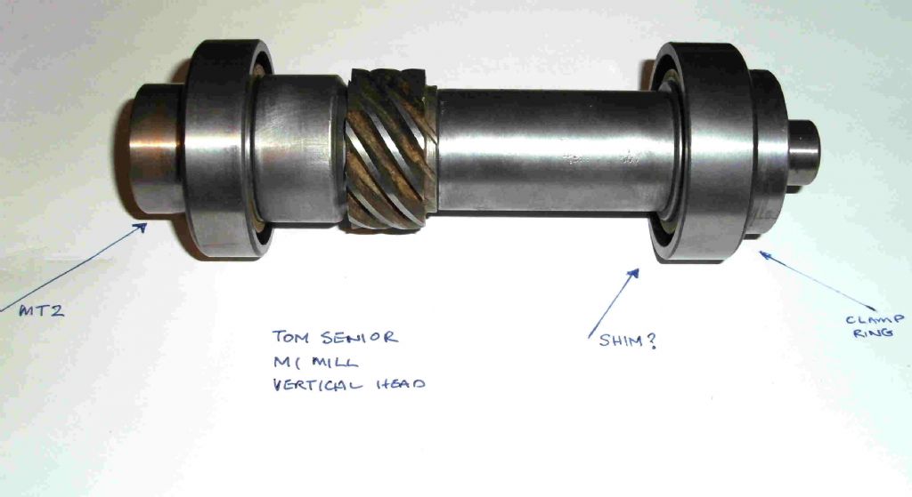
                So, I’ve taken a picture of the shaft as it is at present – assembled, but out of the casting:
                 
                 
                The way I think that it’s supposed to work is that shims shouldn’t be applied to the outside of the bearings at all (which is what you appear to be indicating has happened on yours), but at the point I’ve indicated on the picture. The idea appears to be that you do a trial fit with the bottom end cap in place, and when you screw down the upper cap, you check for end play. Remove the upper cap, release and unscrew the clamp ring, which releases the bearing. Place appropriate shim on the end of the sleeve so that it’s pressing on the bearing inner, replace the bearing, clamp it up again and replace the cap. Then recheck the end float, and probably do the whole thing all over again – possibly several times. Incidentally, the original bearings are Hoffmann thrust bearings, LS10ACD/MS9ACD.
                 
                So, just to be clear, it appears that you adjust the preload by forcing the inner part of the upper bearing more firmly against the upper cap, which has the effect of forcing both bearings apart slightly against both caps. I’m still thinking about where the forces end up with this design, and whether I like it or not. It’s clear that any axial load is taken by the upper bearing  – I can’t see it being any other way. There doesn’t appear to be enough room to double up on the lower bearing as I’d hoped – it would foul the larger drive gear.
                 
                As for a real fix for this, well…
                 
                The thing is that really, the larger sleeve needs to be adjustable in length – with the end caps in place. Whilst you could contrive a sleeve assembly that did this, as there’s plenty of room for it, you’d have to face the prospect of the only way to adjust it being to mill an access point in the side of the casting.
                 
                Of course I’m open to any suggestions about this – none of the above has been confirmed by anybody else; it’s just the results of a sleepless night.

                Edited By Steve Garnett on 16/12/2009 12:08:53

                #46282
                Circlip
                Participant
                  @circlip
                  Don’t ya think that a clamping “Washer” could be fitted between the outer race and the cap??
                   
                      Regards  Ian.
                  #46284
                  Antony Cook
                  Participant
                    @antonycook35332
                    Hello Steve, Found your mail this morning but haven’t had a chance to reply before now.  The bearings on my vertical head were extremely worn (squared balls I think) and I replaced these with the same as you have quoted, so it is obvious that the bore hasn’t been altered at all (I did think at one time time that an eventual shoulder had been removed in order to use another size of bearing).   The state of construction was just as you have described in fact, with a central spacer tube but with the addtion of shims on the top bearing (ie between the outer ring and the end cap).  I thought that this was maybe a “fix” that somebody had made in order to change bearings at some time and thought (as yourself) that this wasn’t  a very good engineering solution.  My attempt to sort this out temporarily, because I needed to mill something quite urgently, was to place a large bore tube between the bearings (with these turned around) such that it pushed against the outside of these.  I cut out a large hole in the middle in order for the main axle to come through.  I was then able to shim up the top end of the axle to give a preload.  This has worked very well, even though the tubing is not retained horizontally in an y way.  This was of course done as a purely temporary measure as I was sure that somewhere someone would have constructional drawings of the head as manufactured and that I could possible reinstate the proper construction.   However drawings don’t exist and I am now lucky that you have found the same as myself, so I know that I can:  A).  replace the original solution or B).  Find a better one than I nao am using.
                     
                    I will probably have time during the Christmas period to look at this again, but let’s keep in touch on this as I have a feeling that anyone changing bearings on such a vertical head is going to find problems, as I think that the original solution was dependant on bearing limits in width.  I would prefer a permanent (and traditional?) solution where the bottom bearing is pressing on a shoulder with the top bearing being shimmed to give preload.  Whether this is possible I don’t know, as it would probably entail using another bearing size. 
                     
                    Happy Christmas – Antony Cook, Langhus, Norway.
                    #46286
                    Steve Garnett
                    Participant
                      @stevegarnett62550
                      Posted by Circlip on 16/12/2009 13:58:34:

                      Don’t ya think that a clamping “Washer” could be fitted between the outer race and the cap??

                       
                      It certainly could – and it would achieve the same result without having to disassemble the whole thing. My only problem with it is that this is a  2 1/4″ OD bearing, with a 7/8″ ID for the shaft. And on a decent unworn bearing, you’d need washers only a couple of thou thick – if that. Despite the potentially easier task of changing them, I think that these washers are going to be a lot easier to fabricate in a smaller size – unless of course anybody can provide information about where to get the items ready-made…
                       
                      But I still don’t like it, and I’m pretty sure that Antony doesn’t either! So I suspect that both of us are likely to spend some time trying to figure out whether there’s a more satisfactory way of achieving a correct adjustment without disassembly.
                       
                      Antony, I’ve read everything you said, and I’m having another careful look at the Sandhu “Spindles” book (WP27). One of my concerns with the existing arrangement is where any axial loading is transmitted – into the top of the casting. Somehow this just seems wrong to me in terms of the applied forces, although I’d be quite happy to be talked out of that by a convincing argument…

                      Edited By Steve Garnett on 16/12/2009 16:04:34

                      #46290
                      Circlip
                      Participant
                        @circlip
                        Two things spring to mind Steve, on me ancient Velo, the compression ratio had an adjustment by putting shims between the cylinder base and crankcase, but more importantly the pre-load for the taper roller MAIN BEARINGS was set by adding shim washers between the back of the outer races and the crankcase bores and checking the spacing between the crankcase halves with feelers. A 4 thou (I think) gap meant that when the halves were torqued up and the engine reached working temp this was the pre-load required for running.
                         
                          Regards  Ian.
                         
                          If you find what the preload spacing is, you could either check with a bearing supplier whether they have shims, get someone to waterjet shimstock or have a go at photo etching some from shimstock.

                        Edited By Circlip on 16/12/2009 16:41:58

                        #46299
                        Steve Garnett
                        Participant
                          @stevegarnett62550
                          Posted by Circlip on 16/12/2009 16:36:45

                          If you find what the preload spacing is, you could either check with a bearing supplier whether they have shims, get someone to waterjet shimstock or have a go at photo etching some from shimstock.
                           
                          Very reasonable suggestions indeed. Unfortunately whatever I do at present is fraught with one particular snag, that being that the head isn’t on the mill and won’t be for a while, I suspect. And without a suitable means of mounting it, there’s no way to measure the clearances, barring an almighty lashup. The other issue that you mentioned in conjunction with your Velo (I remember the forces of Law and Order riding around on those!) is, of course, the actual value of the clearance. Last time I looked, which was about a year ago when I decided that the two mills at work needed rather more servicing than they normally get, all I could find about ‘correct’ preload clearances was that if your head warmed up gently after running at a reasonable speed for a while, and not doing abnormally excessive cuts, you’d got it about right.
                           
                          Trying to reconcile that into any sort of a reasonable specification isn’t going to be easy. I know what that ‘feels’ like on the two mills in question which both have large castellated nuts to adjust the preload, but I must confess that I’d be at a bit of a loss to convert that into a pre-run clearance value, and even if I could figure out a reliable way to measure this on them and they were similar values, would it translate? I don’t know.
                           
                          So at the moment, this is just too many questions, and I suspect no real answers until I’ve put the whole mill back together – after I’ve rearranged the entire workshop, blah blah… anyway, you get the idea. But I’m sure that for both Antony and myself, all suggestions and comments are gratefully received. Even though ideally I’d like a proper quill head for the mill (not so easy to find or pay for), this early existing one has now annoyed me enough to want to fix it better anyway.
                          #46313
                          Steve Garnett
                          Participant
                            @stevegarnett62550
                            Okay, I think I’ve worked out the answer to doing it properly, as Antony and I would like. I’ll do a proper drawing of it as soon as I’m able, but a brief description I can provide now:
                             
                            This is based on what Antony has already done – in other words turning the bearings around so that the thrust force on them is reversed, and putting a sleeve between them. The idea is to get at least the top end cap out of the force equation altogether, and achieve an adjustable preload, preferably using what’s already there – and it can be done. The first thing is that a close-fitting sleeve has to be fixed firmly to the casting at the appropriate place – not too difficult to achieve at all – it could be loctited and pinned, because it never has to come out again once it’s in position. This would enable the axial force to be transmitted into the casting around the centre of the MT sleeve – which is where it should be; as close to the source of the force as possible. All the bottom cap has to do is hold the bearing in approximately the right place for assembly purposes; in the final analysis, it doesn’t even need to do that very well either – it’s pulled against the sleeve from above.
                             
                            At the other end, it gets more interesting. At present, the clamp ring just forces all of the components on the shaft together, and doesn’t provide bearing preload at all. But, if the long shaft sleeve was locked in place independantly (its only function now is to stop the keyed helical gear from moving up the shaft), and it was made very slightly shorter, then the screwed clamp ring would now be free to move the inner race of the bearing in the thrust direction – thus providing the preload adjustment by pulling both inners towards each other. And that effectively takes the top cover out of the equation completely, meaning that the whole assembly can be adjusted just by removing three hex bolts and slackening one locking screw. As far as I can tell, you’d only have to take 25-30 thou off the sleeve end for this to happen, and you wouldn’t run out of thread for the adjuster either – not for quite a distance.
                             
                            At the moment it’s just a thought exercise, but it seems to meet all of the design criteria. Antony, since you have one in front of you, do you have any comments?

                            Edited By Steve Garnett on 17/12/2009 11:10:13

                            #46324
                            Circlip
                            Participant
                              @circlip
                              The “Force” didn’t ride round on Venom Clubmans Steve. Bearing pre-load figures should be obtainable from the bearing manufacturers.
                               
                                Regards  Ian.
                              #46325
                              Steve Garnett
                              Participant
                                @stevegarnett62550

                                Ah, I was thinking about the L.E…

                              Viewing 14 posts - 1 through 14 (of 14 total)
                              • Please log in to reply to this topic. Registering is free and easy using the links on the menu at the top of this page.

                              Advert

                              Latest Replies

                              Viewing 25 topics - 1 through 25 (of 25 total)
                              Viewing 25 topics - 1 through 25 (of 25 total)

                              View full reply list.

                              Advert

                              Newsletter Sign-up