SE(CE) – Yet Another Brick In The Fire-Wall!

Advert

SE(CE) – Yet Another Brick In The Fire-Wall!

Home Forums CAD – Technical drawing & design SE(CE) – Yet Another Brick In The Fire-Wall!

Viewing 7 posts - 1 through 7 (of 7 total)
  • Author
    Posts
  • #614660
    Nigel Graham 2
    Participant
      @nigelgraham2

      Trying to work through Siemens' own tutorials, I found firstly that having drawn that bearing journal, you are left in the lurch, with no clear next stage.

      What if you want to copy it, or add bolt-holes to its base? Journals are often paired a set distance apart, usually facing in opposite directions, and they need bolt-holes that unlike the features so far, are symmetrical about but not on, at least one axis of the co-ordinate indicator. So it would seem logical that the next exercise might address such little matters.

      I found a likely-looking menu, although it suggested no connection to that introductory exercise, and picked what seemed appropriate.

      This is how it told me to open an exercise using a drawing already created by the tutorial authors:

      "

      1: Open a part file

      Start Solid Edge.

      On the Application menu, click Open.

      In the Open File dialog box, set the Look in: field to the folder where the training files reside.

      Click sketch_A.par and then click Open.

      "

      @@@@@ and other words like "Bother!"

      1) Which part file? Any?

      2) Open SE… Opening any data file usually opens its programme, so no surprises there, but should not be necessary.

      The Application > Open command gives two choices; a new drawing from templates, or "Browse" , which opens your own folders.

      My PC keeps my SE attempts live in the same folder as my TurboCAD drawings, and I forget if that was my choice or automatic.

      3) "Look in… " There is no "Look in".

      What is the training-files folder called? Does it even exist? Do the files? No idea: their "Look in" link does not.

      Perhaps they are hidden like that wretched micrometer, which made a brief appearance without any clear reason how, why or whence, then vanished again. Schroedinger's cat? It certainly behaves like it but I was thinking more of one from a certain Midlands county, only without the grin.

      I think the on-line tutorials are for a different edition of SE, probably the full industrial one; not CE. They have things in common of course, but do not match fully.

      .

      While I am failing dismally to try to learn what I thought would be simpler than the horrendously difficult TurboCAD, and certainly with more help available, I am forgetting how to use my original choice. Perhaps I will reach an equilibrium: learning to make an isometric drawing of a plain cube in SE whilst losing all except how to draw its orthographic elevations directly in TC; and so unable to do anything more advanced in either!

      Now, where did I put my drawing-instruments and Rotring pencil-leads…?

      Advert
      #21399
      Nigel Graham 2
      Participant
        @nigelgraham2
        #614668
        Grindstone Cowboy
        Participant
          @grindstonecowboy

          I get the feeling that the first line of instructions – in this case "Open a part file" is more like a title and tells you what you are about to do, the subsequent lines give you the actual step by step instructions on how it is achieved.

          Possibly could be better written.

          Rob

          #614673
          Nigel Graham 2
          Participant
            @nigelgraham2

            You could well be right. I thought similarly, as it seems to make the instructions loop back on themselves and put themselves out of order. It certainly is ambiguous.

            I found it best to read the instructions for several steps ahead to gain some idea of where each section is leading, before laboriously switching back and forth between the two open sets of software.

            Though in this case, once I'd opened the programme, what they wanted me to find still did not appear anywhere.

            #614679
            Grindstone Cowboy
            Participant
              @grindstonecowboy

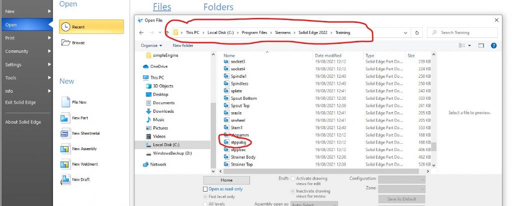
              If you have a look here, you will find that the file sketch_A.par has to be downloaded as a zip file – which could then be extracted to wherever you like. The training files that come as standard with the installation seem to default to C:Program FilesSiemensSolid Edge 2022Training so that is probably as good a place as any.

              It would seem best to start at the beginning of the tutorials and work completely through them in order, rather than popping in and out and choosing bits that seem to cover what you want to do. I don't think there are any short-cuts to the learning process, unfortunately.

              Rob

              Links to https://docs.plm.automation.siemens.com/data_services/resources/se/2020/se_help/training/en_US/xid1012412/index.html?goto=activity_sketching_part1.html

              #614719
              SillyOldDuffer
              Moderator
                @sillyoldduffer

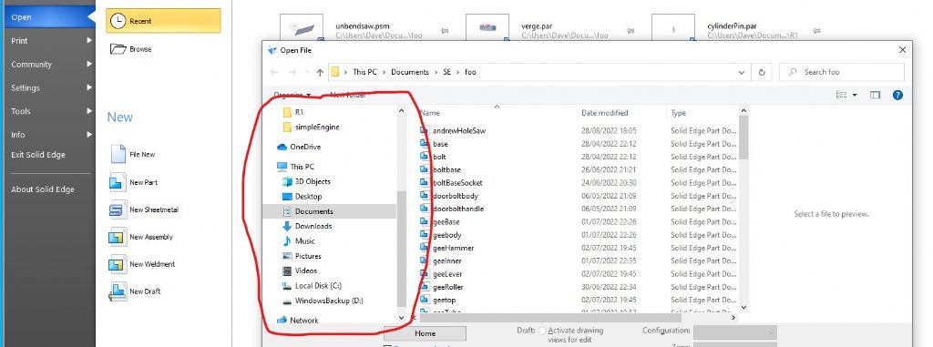
                Wot grindstone said, but what they mean by 'Look In' is usually called the 'Navigation Pane', ringed in red below. It allows the user to find, or navigate to, or 'look in' a particular folder:

                lookin.jpg

                On my copy of SE the training material is preloaded, and the Navigation Pane is used to get it:

                training.jpg

                Nigel also says of the bearing journal : What if you want to copy it, or add bolt-holes to its base? Journals are often paired a set distance apart, usually facing in opposite directions, and they need bolt-holes that unlike the features so far, are symmetrical about but not on, at least one axis of the co-ordinate indicator.

                The desire to 'copy it' is leaping ahead, and perhaps indicates a misunderstanding of how SE works. A part usually defines a single component. Parts are combined in Assemblies, which is another SE document type and tool-set.

                Thus a railway wagon might start as an Assembly of a Frame, Axle, Journal and Wheel parts, each of which is defined only once, but multiple copies can be added to the assembly:

                • One Frame Part with
                • Four instances of the journal part attached at appropriate points on the frame
                • Two instances of the axle part, joined to holes in the journal pairs to allow rotation
                • Four instances of the wheel part, each joined, non-rotating, to the ends of the axles.

                Note that the CAD Assembly is just like a real one, with parts being fitted together to create a realistic representation of the whole, including movements. Having defined parts, they behave like lego bricks. The position of a journal pair is determined by the frame, not by the journal's original coordinates (which unlike a 2D drawing) don't matter much.

                At this stage of learning I recommend concentrating on mastering single part production. Adding holes to parts can be done with the Hole tool (best for threaded, counter-sunk, etc.) or by sketching a circle on a face and extruding it minus.

                I strongly recommend going with the flow rather than expecting the tutorials to fit with whatever the trainee thinks is logical. As computer systems don't know or care what the user wants they always win a battle of wills. I find it best to take notes for later rather than deviate too much from the course. What definitely doesn't work is attempting advanced stuff before a good chunk of the basics have been nailed.

                Dave

                #614819
                Nigel Graham 2
                Participant
                  @nigelgraham2

                  Thank you Dave.

                  I am afraid it still doesn't work.

                  I can assure you I was doing my best not to jump ahead. Your outline of assembling parts into the whole thing show that is far more advanced than I have reached.

                  I followed the second tutorial I had found (the first was the mystery micrometer) and managed to complete its first exercise, a simple L-shaped journal. The tutorial sort of suggested the exercises progress from there, using that journal.

                  Even with that I discovered SolidEdge is not all it seems because the instructions do not always match what appears on the screen.

                  So I set out to try the next exercise in the sequence; but it opened a third set! The journal's companion exercises had gone the way of the micrometer.

                  I picked what appeared the simplest – using a prepared drawing to show how to copy and move objects, which I had naturally thought among the major, most basic features in any CAD programme. Well, useful ones, perhaps.

                  This is where I hit the end-stop; with Siemens' phrase "Look in" which seemed a tool-name, but which you tell me is really called the "Navigation Pane". So why didn't it use the proper name and path?

                  I have just tried searching, using the clues you give above. It lets me browse my PC, but the only SE drawings in there are my own attempts. This revealed that I had stumbled across yet another tutorial, drawing a rectangular Z-shaped bracket. I have no idea where that came from!

                  '

                  CAD is extremely difficult to learn anyway, but SE seems made as difficult and confusing as possible.

                  I must have spent hundreds of hours – and umpteen kW/h electricity – trying to learn CAD.

                  I progressed just enough with TurboCAD first, to make very rough orthographic drawings. Its 3D "model" mode is impossible; as is its very strange paper-printing system. It cost ££ too, this did.

                  Now with Solid Edge (Community Edition): 3D-first but appearing to be easier, slightly better documented and having none of TC's horrendous traps. Though a quick look at its "Print" tool suggested that is little better than TC's "Viewport" nightmare.

                  It's not much help "nailing" the basics, though, if they won't let you.

                  .

                  I knew before I started what CAD can offer expert users – the drawing-office at work used SolidWorks – and though I realised it would not be easy to learn, I thought it might genuinely help my model-engineering.

                  Right on the first point; half right on the second (not just "not easy" ; virtually impossible). Completely wrong on the third.

                  The two magazine are now full of pretty-coloured images of machinery, their workshop drawings to full CAD quality, photos of 3D-printed things, and articles on CNC machining. All beyond me, but I was not aiming for those lofty heights. I wanted only to draw efficiently, things I want to design, to help me make them.

                Viewing 7 posts - 1 through 7 (of 7 total)
                • Please log in to reply to this topic. Registering is free and easy using the links on the menu at the top of this page.

                Advert

                Latest Replies

                Viewing 25 topics - 1 through 25 (of 25 total)
                Viewing 25 topics - 1 through 25 (of 25 total)

                View full reply list.

                Advert

                Newsletter Sign-up