SE (CE) – Any Manuals Available, Please?

Advert

SE (CE) – Any Manuals Available, Please?

Home Forums CAD – Technical drawing & design SE (CE) – Any Manuals Available, Please?

Viewing 12 posts - 51 through 62 (of 62 total)
  • Author
    Posts
  • #610979
    Grindstone Cowboy
    Participant
      @grindstonecowboy

      Typing "solid edge synchronous mode" into a search engine brought this up as the top result – " Solid Edge synchronous technology allows you to rapidly create new concept designs, easily respond to change requests, and make simultaneous updates to multiple parts within an assembly. "

      So I guess they are using it to mean simultaneously.

      Rob

      Advert
      #610980
      lee webster
      Participant
        @leewebster72680

        Your enthusiasm in persevering with Solid Edge gave me the incentive to try it again. It isn't an easy programme to get to grips with, especially after using a simple CAD programme like Designspark. But after about 15 minutes I had drawn half a model engine conrod, added draft to relevent edges and fillets to others. I then went a step further and hollowed it out, a resin 3D print can consume a lot of resin. There are parts of the programme I find awkward, but that is more likely to be me. I exported an STL of the conrod and it loaded fine in my slicer software.

        Is the link for the text files in this posting? I might start spending more time with the programme.

        #610998
        IanT
        Participant
          @iant

          Hi Lee,

          I think Nigel is referring to this set of Siemens self-paced learning courses – which covers a lot of useful ground.

          Solid Edge – Self Paced Learning

          If you select a course, you will find that for most of them, Siemens has provided a PDF of the course material, as well as Powerpoint slides and 'Activity' data. The production quality is excellent. However, the 'content' PDF is effectively a pretty good manual on that topic in it's own right (and is indexed) – so has dual use in my view.

          Have a look at the 'Sketching' course content PDF to begin with…

          Regards,

          IanT

          #611013
          Nigel Graham 2
          Participant
            @nigelgraham2

            Grindstone –

            Aha! The problem is that when you start trying to learn SolidEdge it says only you "need" use Synchronous mode without explaining it or why, then later ties it and 'Ordered' in with modelling solid objects.

            No mention of multiple files though I noticed the templates menu defines many as "part" files. It's curious that you discovered that facility only by an individual search external to SE's own site.

            '

            Lee, IanT –

            Yes, I have now found Siemens' introductory, pdf, based manual; thankyou. It is not immediately obvious because the web-site tends to deter you with jargon making you think it's only for people with considerable CAD experience, perhaps moving to Solid-x from another make.

            The manual is well over 1000 pages long, including exercises and much white space; but its Contents list is concise and explanatory enough for navigation.

            My 'Excel' edition of the 'Contents' takes just 2 A4 sides, and I don't need prepare an alphabetical-index version as I did with TurboCAD's far more tortuous guide. It creates a print as simply a read-access physical aid not strictly necessary, to searching the digital manual itself.

            TC's on-line guide is not an introductory manual but a full commands glossary; and I needed re-write its original, long, tangled 'Contents' list for clarity.

            '

            Polygons….

            I'd wondered "aloud" in my previous post about a polygon tool.

            I recalled later that SE has a command-search tool, and that obligingly produced a very neat polygon-creator indeed. I tried it, and I like it offering size by mid-point (across-flats radius) or vertex; and angular alignment. That radius option immediately facilitates for example linking a polygon to its related circle, like a square or hexagonal section on a shaft of close across-corners diameter.

            (I know the workshop formula for relating a square section of side S to round: Diameter = (sq.rt 2)S. I'd have to look up that for a hexagon.)

            #611022
            lee webster
            Participant
              @leewebster72680

              Thanks IanT and Nigel, I will check out the link later. I have two 3D printed sprues to sand smooth!

              Lee

              #611050
              SillyOldDuffer
              Moderator
                @sillyoldduffer

                Don't get hung up on Ordered versus Synchronous. With few exceptions it's more convenient to work synchronous mode, with Ordered in reserve if necessary. So ignore Ordered for time being.

                Here's an example to show the difference. The example is a cube with a hole in it, where I decide later to move the hole and alter its diameter.

                FreeCAD and most other 3D-CAD packages are Ordered.

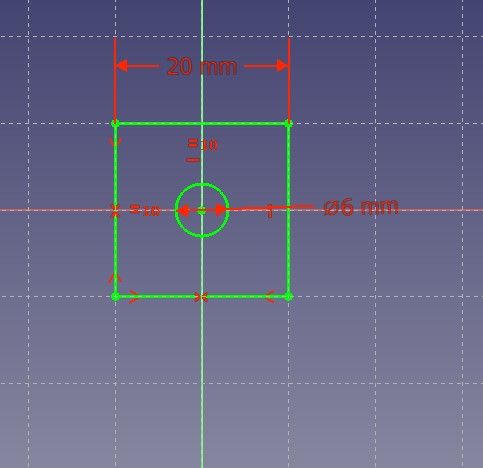
                Step one is to 2D Sketch and dimension a square with a circle representing the hole.

                cubesketch1.jpg

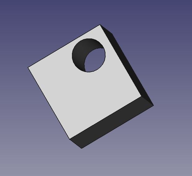
                The sketch is then extrude by 20mm to create the holed cube:

                cube3d.jpg

                I realise the hole is too small and should be off-centre. In Ordered (aka History), this is done by editing the original sketch:

                cube3dsketch2.jpg

                The extrude is automatically re-applied when the sketch is saved:

                cube3dmoved.jpg

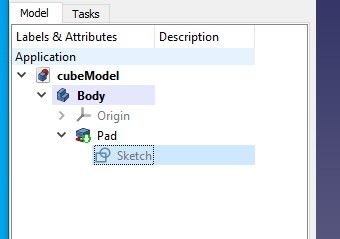
                So in Ordered Mode, models are a stack of sketches each building on previous work. All the sketches are retained within the time-line and can be edited to alter the model, in my example by moving the hole. Below the cubeModel model consists, in order, of a Body, which has an origin, containing a Pad (Extrude), which depends on a Sketch

                cube3dhistory.jpg

                Solid Edge has a Synchronous Mode as well. In synchronous mode, sketches are used to start the model, but thereafter the model is modified directly, and the sketches become redundant.

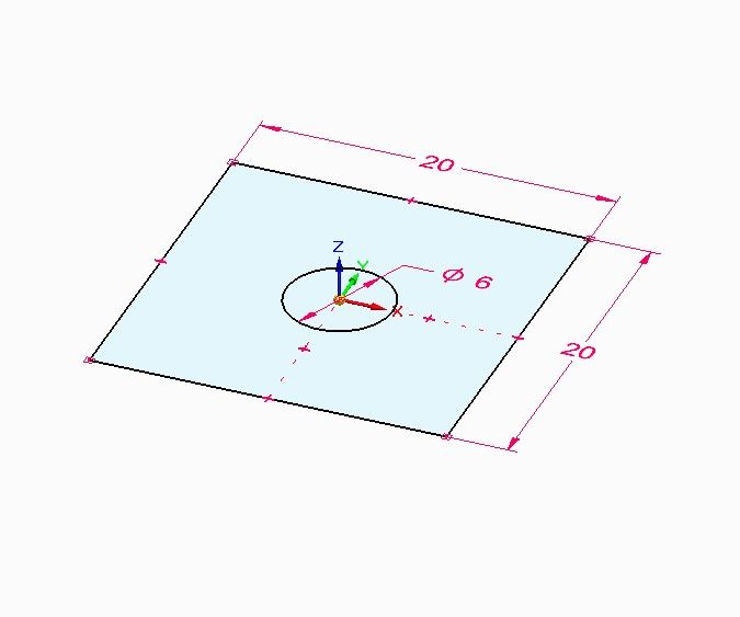
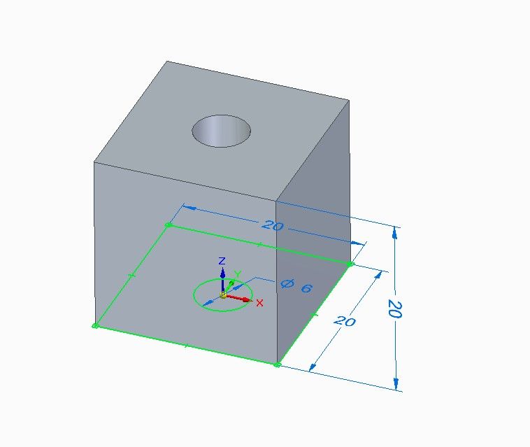
                Step one is identical to Ordered Mode. A sketch is drawn and dimensioned:

                cube3dsync.jpg

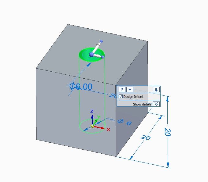
                And the sketch is extruded in exactly the same way:

                cube3dsyncextrude.jpg

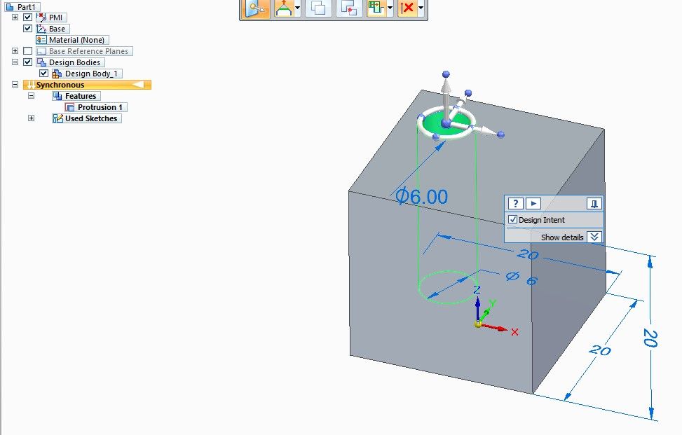
                The difference between ordered and synchronous appears when a synchronous cube is changed. The hole is changed directly on the model, not by editing the sketch. Pointing and clicking on the hole activates a wheel tool that can reposition the hole:

                cube3syncwheel.jpg

                The hole can be dragged and rotated, here dragged:

                cube3dsyncdragged.jpg

                Note that in synchronous mode, the part breakdown (list left) is a Protrusion (the holed cube) that doesn't depend on a sketch, and there's a container of Used Sketches. Changing the model in 3D invalidated the 2D sketch, so SE archived it. It soon becomes impossible in Synchronous mode to change the model by altering sketches. Synchronous models don't have a sketch history, so the model is changed by moving forward rather than going back to an earlier state.

                In practice changing the model directly rather than editing sketches works well, but there are times when Ordered mode does a better job. Solid Edge models can be Ordered, Synchronous or a mix of both. Everything I've needed to do so far has been achieved comfortably in Synchronous mode – it works.

                In short, ordered mode depends on 2D sketches, which remain important throughout, whilst synchronous mode only uses 2D sketches to start the ball rolling and then drops them.

                Dave

                Edited By SillyOldDuffer on 24/08/2022 16:47:48

                #611075
                Nigel Graham 2
                Participant
                  @nigelgraham2

                  Ah, I see!

                  Thank you Dave!

                  The manual does not explain it as clearly as you have, though perhaps following their instructions reveals the secret eventually. They do say you can mix the two modes in one drawing but I feel that at a beginner's stage it's probably safest to use only the default synchronous mode used by the exercises.

                  If you wanted to produce similar objects later, using all-synchronous mode, could you save the starting 2D sketches as drawings in their own right, in their own files, and open them to "Save As" then modify as needed for the later drawings ? (With meaningful file-names to help retrieving them. A large sketch library might need a 'Word' or 'Excel' index in the same folder.)

                  I was surprised to find that extruding the 2D sketch works (to use your example) both the square and the circle together to make a cube with a hole through it. I met that yesterday, experimenting as the instructions suggest with the first exercise's sketch, and working a little further ahead.

                  I assume it's because the system extrudes the area between closed boundaries, rather than extending separate boundaries individually. Reading about extrusions further, and looking at the '+/-' sign on the tool's menu, I see you cut out material by extruding the removed shape back into the surroundings from the surface, so a the subtraction is semi-automatic. So presumably the Hole tool is a dedicated version of that routine, to facilitate one of the most common moves.

                  . . .

                  Alibre thinks I'm still here. I received out of the blue today, an e-mail promotion from it!

                  #611086
                  lee webster
                  Participant
                    @leewebster72680

                    I didn't like synchronous mode when I first tried Solid Edge. But now I've heard it described in that way I realise that it's very close to the way Designspark works. I think in other systems it might be called direct modelling. Now that I have used Dspark for so long I might actually get along with synchronous mode in Solid Edge!

                    #611092
                    IanT
                    Participant
                      @iant

                      "If you wanted to produce similar objects later, using all-synchronous mode, could you save the starting 2D sketches as drawings in their own right, in their own files, and open them to "Save As" then modify as needed for the later drawings ? (With meaningful file-names to help retrieving them. A large sketch library might need a 'Word' or 'Excel' index in the same folder.)"

                      Or just regularly 'save as' your part/assembly (with a simple version no.) to keep track of progress. I don't do this so often now but it was very useful at first when my confidence was low. It's very quick/simple to do…

                      Regards,

                      IanT

                      #611101
                      Nigel Graham 2
                      Participant
                        @nigelgraham2

                        Good point Ian – it's normal anyway of course to keep files saved every so often, but I'd in mind a store of starting-points for other work of basically similar type.

                        #611103
                        SillyOldDuffer
                        Moderator
                          @sillyoldduffer

                          Posted by Nigel Graham 2 on 24/08/2022 19:03:24:

                          If you wanted to produce similar objects later, using all-synchronous mode, could you save the starting 2D sketches as drawings in their own right, in their own files, and open them to "Save As" then modify as needed for the later drawings ? (With meaningful file-names to help retrieving them. A large sketch library might need a 'Word' or 'Excel' index in the same folder.)

                          I was surprised to find that extruding the 2D sketch works (to use your example) both the square and the circle together to make a cube with a hole through it. I met that yesterday, experimenting as the instructions suggest with the first exercise's sketch, and working a little further ahead.

                          I assume it's because the system extrudes the area between closed boundaries, rather than extending separate boundaries individually. Reading about extrusions further, and looking at the '+/-' sign on the tool's menu, I see you cut out material by extruding the removed shape back into the surroundings from the surface, so a the subtraction is semi-automatic. So presumably the Hole tool is a dedicated version of that routine, to facilitate one of the most common moves.

                          . . .

                          Similar for later is best done with 3D models rather than saving sketches, which is just as well because I don't know of a way of saving them meaningfully! Instead libraries of 3d parts can be created, and a number of hardware vendors allow parts to be downloaded in CAD form from their online catalogues – there's no need to design your own standard parts like hinges or nuts and bolts. See this example. With luck, a CAD assembly consists of existing parts more like Meccano than 2D drawing and metalwork.

                          Yes, extruding +/- from closed boundaries, which SE identifes by shading them. The wheel tool works on faces too, allowing objects to be stretched or squeezed, at an angle if necessary. I find SE's automatic extrude/cut unreliable – might be doing it wrong.

                          Holes made by a sketch can be any shape, such as a hexagon. The hole tool does round holes only, but can add counter-sinks, threads, and the angled bottoms left by a twist drill etc. I usually make holes by sketching but the Hole tool is very useful for countersunk or counterbored holes.

                          Dave

                          #611115
                          Nealeb
                          Participant
                            @nealeb

                            Extrusion works on the area between two boundaries, as noted. Couple of additional points worth mentioning, though. The first is that you can select more than one area (hold down "shift" while clicking on regions) to extrude at the same time. This means that even if there seem to be extraneous lines crossing the area you want to extrude which seems to divide the area you want, you can just click on both sides and pick both. Which then leads to the point that a sketch is not a "drawing". You absolutely do not need to tidy odd lines and so on in a sketch; a sketch is a means to an end and once used (in synchronous mode) will be ignored thereafter. So, for example, if you want to extrude a rectangle that has a circular arc cut out of one corner, you could carefully draw an arc, trim out the excess lines, and extrude the remaining shape as desired. Or you can just draw a circle centred on the corner of the rectangle and just select the area you want to extrude and ignore all the additional lines. Saves time although it upsets the traditional draughtsman! But this is a sketch – not a finished drawing…

                            SOD has also mentioned reasons for using the hole tool rather than extruding. This just emphasises the fact that you can often achieve the same end by different means. Creating a circle in a sketch and then extruding is great for a hole that goes right through the part, and is also useful for non-circular holes. However, the hole tool is really useful for counterbores/countersinks/part-depth holes – or holes that go through more than one part in an assembly.

                            Edited By Nealeb on 24/08/2022 22:22:32

                          Viewing 12 posts - 51 through 62 (of 62 total)
                          • Please log in to reply to this topic. Registering is free and easy using the links on the menu at the top of this page.

                          Advert

                          Latest Replies

                          Viewing 25 topics - 1 through 25 (of 25 total)
                          Viewing 25 topics - 1 through 25 (of 25 total)

                          View full reply list.

                          Advert

                          Newsletter Sign-up