SE _ First Successful -ish Attempt…

Advert

SE _ First Successful -ish Attempt…

Home Forums CAD – Technical drawing & design SE _ First Successful -ish Attempt…

Viewing 17 posts - 1 through 17 (of 17 total)
  • Author
    Posts
  • #614190
    Nigel Graham 2
    Participant
      @nigelgraham2

      All right, the first exercise in Siemens' tutorial set. Years from any real design-drawings of my own.

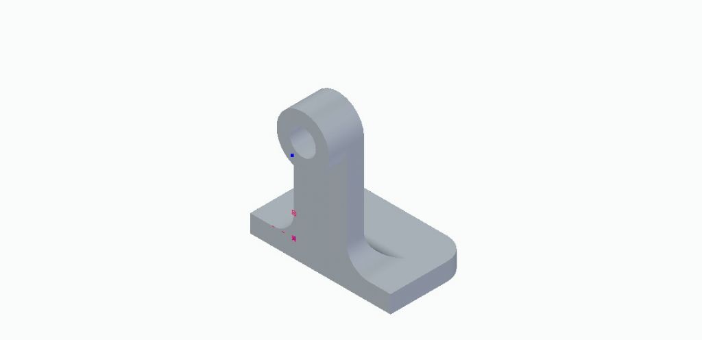
      It is a journal for a simple roller assembly – basically an L-bracket with a hole through a boss on the upright. I think a later exercise incorporates it and a twin, in the entire assembly.

      Not easy…..

      It starts by drawing a rectangle but it is very hard to select the correct plane (the XY) for this.

      Then I found –

      The various tools and their results do not always agree with what the instructions tell you to expect, e.g. by symbols not showing; no "Quickpick" tool).

      The diagram showing the three planes appears or not according to its own whims. Similarly with trying to select the plane from that three-arrow sign.

      The order of instructions is confusing in places. I found it best to read several ahead to see what we are aiming for.

      Eventually I reached the last stage: a fillet round three corners. The fillet tool itself is easy – really rather elegant – but the problem is picking hidden corners. Either I missed it or the instructions do not tell you to use the Style tool to show them. I found that by guess-work after turning the thing in all sorts of improbable angles to find the corners.

      Eventually, feeling teaching Schroedinger's luckless cat to dance (or not!) would be easier, I managed to save the result:

      se exercise - journal.jpg

      That was on Saturday evening. Yesterday (Sunday) evening, flushed with success I tried to see what had sunk in, with my own creation, a Tee-nut. Nominally simpler: two blocks stuck together with a central hole. I was not going to try to be too clever and represent the thread. (On a real drawing I would only add a text-note anyway.)

      Once again all sorts of random stabbing and hovering around that pestilential axes trident until I managed to draw a symmetrically-placed Base rectangle flat on the floor. The default seems to be the vertical plane. Poor [Esc] key!

      In doing so I had somehow drawn a rectangle with one corner on the trident's hub. Deleting that was very difficult – it is not obvious how, and the command-finder told me the expected commands are inactive in this edition of SE! What? "Delete" and "cut" are basic editing tools in almost all software!

      Once I'd made the extrusion arrow appear (another fight) I made the base block, sized it, then created the narrower upper part… which obligingly displaced itself 2 or 3mm endways; impossible to centre.

      I gave up at that point.

      Advert
      #21398
      Nigel Graham 2
      Participant
        @nigelgraham2
        #614197
        Ady1
        Participant
          @ady1

          All these CAD things can drive you potty in the early stages

          I learnt a bit of Design spark years ago and left it at that, you have to be quite dedicated to use them seriously

          I just use it for basic sketching and size/fitting purposes

          A decent mouse helps too, when things get fiddly

          Edited By Ady1 on 19/09/2022 22:09:12

          #614214
          John Hinkley
          Participant
            @johnhinkley26699

            When I started with 3D, I tried innumerable – mostly free, or free trial packages – and couldn't get the hang of them at all and eventually gave up.

            Latterly, I changed my approach to the design process. I took the view that it would be better (for me) to ask myself the question: "how I would make that part in real life?" and that worked for me. For example, your tee-nut. You wouldn't make it from a rectangle and then plonk another, smaller one on top, would you? No. Draw the tee shape on a plane. It doesn't matter which, for now. Extrude that shape for a distance equal to the length of the nut. Result: one tee nut. Select the top (or bottom) plane, draw a circle in the middle the size of the tapping hole and then extrude/remove it as if drilling it out. Job done. The same principle can be applied to other, possibly more complicated parts, before making them into an assembly separately if needed. The process really isn't that difficult, but I have to admit that SE/CE seems, from your descriptions of the fight you are having with it, to be particularly tricky to master!

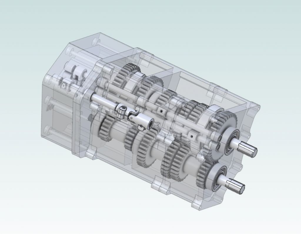
            Here's one I did later:

            Gearbox in see-through nightie

            Good luck with your endeavours and perseverance is the answer.

            John


            Edited By John Hinkley on 20/09/2022 09:43:21

            #614216
            Nigel Graham 2
            Participant
              @nigelgraham2

              Thank you John.

              Yes, it did occur to me later I could have started with a T-shaped Base figure, but I was trying what the tutorial had used, to consolidate that, before going on to other techniques. Perhaps it would have worked better if I had developed the upper part on the end face, not top, of the first block.

              Your gearbox is far in advance of what I can manage! Being honest, it always will be.

              I had been using TurboCAD, which allows a direct 2D/3D choice (you cannot mix them – you need choose at the start); and though most of my drawings in that are all orthographic I made a slight advance in its 3D "model" mode. That though is fiendishly complicated, partly because it uses at least two mathematical generation methods for solids, each with its own reactions to the editing tools, and no clear pattern to it.

              SE seems, so far, to use only one set of generation methods behind the screen, so your carefully-extruded figure does not shatter into lots of irretrievable facets when you try to alter it!

              I like too, SE's active dimension system. TC allows "associated" (reactive) dimensions, that track your changes, but you need alter the figure itself with that risk of disintegration (in 3D). I've noticed you need be careful which way the dimensions point, in their tool-menu; but I don't know the right way to use it.

              #614226
              Nick Wheeler
              Participant
                @nickwheeler

                Your carefully-extruded figure is exploding because the care really needs to be spent on the profile you extruded it from. The profile should be fixed so that its lines and geometry stay where you intend them to be. That means the relevant horizontal/perpendicular/tangent/parallel/coincident/etc constraints are more important than the dimensions, so they're defined first. Just because you drew a line that looks like it starts at another point doesn't mean it actually does. It can be more reliable, and much less frustrating, to draw your new item near where you want it, and force it into place with constraints.

                That's why you want the part to be 3 dimensional as soon as practical, so the new features are referenced off the existing rigidly defined ones. The threaded hole in your T-nut example could be placed in the centre of the top face in a number of ways that make it stay in the centre if you later change any of the other dimensions. The T-nut itself has such an obvious profile that can be completely defined using two rectangles, two midpoint constraints and three dimensions. Or it could be projected from the slot it fits if you've already modelled that.

                #614227
                Jelly
                Participant
                  @jelly

                  Your experience is very similar to mine when i picked Solid Edge back up after a decade or so of not using it (they changed from "Ordered" only to "Synchronous" being preferred in that time).

                  Initially it was like wading through treacle, but I kept pushing through and suddenly after a couple of tutorials and modeling some simpler parts of my own, it just clicked and it was all upward from there.

                  It probably doesn't help that Solid Edge has been rapidly gaining feature-sets all the time and is growing from its user friendly roots to be more and more of a full-featured professional CAD package aimed at medium sized organisations who don't need the complexity of Siemens NX, Catia or Pro/E, but do have a dedicated in-house design engineering office.

                  My experience is that the Siemens help is extremely comprehensive, and reasonably easy to search, but not always clear (my most frequent frustration is learning that there's a button to do exactly what I want, but not being given any indication as to where i would find this in the +10 ribbon menus that form the UI).

                  You should expect to have a similarly infuriating experience when you start using the assembly, sheet metal and weldment environments but that each of those will suddenly get much easier one day with some use.

                  With respect to not being able to manage something like John's gearbox assembly, there's a (not very) secret…

                  When I've modeled similar things in Solid Edge, using the engineering reference feature in the edge-bar for assembly mode to auto-generate parts (like gears) to established standards based on either dimensional (I want a Mod 4 gear with a PCD of "x"mm) or functional (I want a DP gear to give me a 2:1 ration at 1500 rpm and 2hp) inputs is usually my first step.

                  This makes it a lot easier to make those complex assemblies as you can start by generating and aligning the business end of the mechanism so it will work as required, then use that model of the functional parts as a reference to model the shafts, frames, bearing seats, bearings, etc. which will hold it all together.

                  In my experience you don't have to hold quite as much in your head all at once that way because you're getting the functional design decisions done quickly, then moving on to a new set of decisions about how you will manufacture a given assembly rather than juggling lots of competing decisions.

                  ​​


                  As a thought Nigel, If you find yourself getting stuck with something repeatedly and would welcome a second pair of eyes to help you get past a particular obstacle, drop me a private message and I'd be only too happy to arrange to go through a problem you're having on Teams/Zoom/[Insert Video-Conferencing Software of Choice Here].

                  I'm not about to claim to be an expert draftsperson or CAD modeller, but I have used SE for a long time now, to do some relatively complex design work for various research projects and am pretty confident with it.

                  Edited By Jelly on 20/09/2022 11:23:35

                  Edited By Jelly on 20/09/2022 11:24:11

                  #614234
                  PatJ
                  Participant
                    @patj87806

                    Learning 3D modeling is like taking a ride on a jet aircraft, and departing during a thunderstorm.

                    Looking out the window, everything is foggy, menacing, foreboding; dark clouds, streaks of lightning.

                    After a few minutes of very low visibility, sudden you break through the cloud cover, and you may see a magnificent sun on the horizon, with a spectacular clear view of an untold distance in all directions.

                    While you are down in the mix, it all seems like total chaos.

                    When you hit "that level" where you break through the fog, then all of a sudden you can see clearly where you are going.

                    It was like that for me, but I was in the fog for quite a while (about a year), and it took me a long time to figure out which way was up.

                    .

                    Edited By PatJ on 20/09/2022 12:18:29

                    #614242
                    Nigel Graham 2
                    Participant
                      @nigelgraham2

                      Thanbkyou…

                      Nicholas.

                      Exploding solids. I ought have been a bit clearer. That remark applies to TurboCAD with its two or more hidden solid-generating methods, whereas I think SoldEdge uses just one; and it applies irrespective of shape.

                      TC offers a library of 'Primitives', about 10 basic 3D forms you can edit so suit. This is a very useful, direct tool: select the Primitive, type in the dimensions, and there it is. TC also allows generating solids by extruding plane figures (as in SE) and that can include the thinnest dimension being line width; useful e.g.for plate metalwork or plywood.. Whichever you use, though, holds traps I never winkled out. Trying to lengthen something can move it instead, and certain tools fragment it unexpectedly into infinitessimally-thin surface facets you cannot re-assemble.

                      As far as I have found, SE does not have these problems that make TC's 3D mode so difficult to learn.

                      .

                      Jelly –

                      All the serious CAD programmes are intended primarily for industrial use, so will have lots of "extras" we amateur users are not likely to need. That's true though of MS 'Word' and 'Excel', as well, and usually we can avoid the peripheral routines.

                      Regarding finding tools, I have discovered, and used the Command Finder, and that is a very useful feature. A bit disconcerting though when it tells you that commands you would naturally expect in all editions of SE, are not in the one you are using!

                      I am a very long way from drawing assemblies, though I suspect even if I learn to draw an elegant folded sheet-metal part, actually making it is another matter. I think the Black Arts of bend allowances and of using a jenny, make sheet-metal work one of the hardest of the metalworking skills!

                      .

                      Pat –

                      I like the simile! Trouble is, I keep losing altitude again, back into the clouds.

                      #614243
                      SillyOldDuffer
                      Moderator
                        @sillyoldduffer

                        Posted by Nigel Graham 2 on 19/09/2022 21:12:22:

                        Once again all sorts of random stabbing and hovering around that pestilential axes trident until I managed to draw a symmetrically-placed Base rectangle flat on the floor. The default seems to be the vertical plane. Poor [Esc] key!

                        In doing so I had somehow drawn a rectangle with one corner on the trident's hub. Deleting that was very difficult – it is not obvious how, and the command-finder told me the expected commands are inactive in this edition of SE! What? "Delete" and "cut" are basic editing tools in almost all software!

                        Once I'd made the extrusion arrow appear (another fight) I made the base block, sized it, then created the narrower upper part… which obligingly displaced itself 2 or 3mm endways; impossible to centre.

                        Nigel's bumped into a few things I also found quirky when learning Solid Edge!

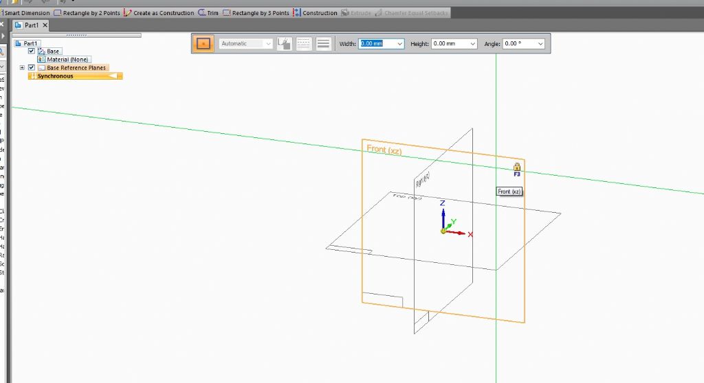
                        Setting the plane at the beginning, here the trick is to move the mouse until until the wanted plane illuminates in yellow, then press F3 to lock it. There is no default plane.

                        Hint: F3 is very important in Solid Edge – used a lot to make sure sketches and selections are locked to the correct plane or face.

                        sestartplane.jpg

                        The Quickpick tool only operates when a choice is ambiguous.

                        Delete seems a bit haphazard: sometimes highlighting followed by one press of the delete key works, sometimes two presses. Other times it's easier to cut with a right mouse click if the option is allowed. I may be doing it wrong!

                        'command-finder told me the expected commands are inactive in this edition of SE': a message like that usually means that the command isn't appropriate in the current context. The idea is to reduce noise by hiding tools that don't do anything useful in this context, for example when working on a Sheet Metal model, only sheet metal related commands are available unless the operator switches to one of the other modes.

                        Making the extrusion arrow appear. It's necessary to click and wait briefly before it activates, and perhaps to select which object in the model the arrow will act on. (Actually, the arrow is the tip of an iceberg called the Steering Wheel tool, which does more, and can be confusing those functions are activated accidentally. An example below.)

                        SE is good at centring at the sketch stage. I'll try and post a picture later.

                        Also should be possible to move the block in 3D. Select all the visible faces of the part to be moved, then get the extrude arrow on one face. Then pulling the arrow should move the highlighted group. Might be better to save this more advanced trick for later!)

                        Persevere!

                        Dave

                        #614260
                        Nigel Graham 2
                        Participant
                          @nigelgraham2

                          Just tried that.

                          I opened a new template ("metric part" ), and the 3-way sign was there in the middle.

                          Pointing to it, made it all turn yellow, and in splendid isolation.

                          I pressed F3 and it was now that the three planes appeared.

                          The X-Y was highlighted, and I could centre a test rectangle on the origin, but because the plane-frames don't appear until pressing F3, there seemed nothing to indicate I had actually selected that plane by choice and not chance.

                          Edited By Nigel Graham 2 on 20/09/2022 15:01:05

                          #614280
                          IanT
                          Participant
                            @iant

                            I think most of the issues (and thier solutions) have been already been covered;

                            Use of 'Command Finder' to locate the icon you want or go to Help – but you can also have a simpler UI if you wish.

                            Icons/Commands are context sensitive, as are file types – so (for instance) you can only save a DXF from a 'Draft' drawing – not a part or assembly one.

                            You can see (or hide) planes by using the 'Base Reference Planes' tick box on the L/H side of the drawing – the drop down let's you show/hide individual planes. Same with dimensions & base reference by using 'PMI' and 'Base' boxes.

                            Regards,

                            IanT

                            #614290
                            SillyOldDuffer
                            Moderator
                              @sillyoldduffer
                              Posted by Nigel Graham 2 on 20/09/2022 15:00:13:

                              Just tried that.

                              I opened a new template ("metric part" ), and the 3-way sign was there in the middle.

                              Pointing to it, made it all turn yellow, and in splendid isolation.

                              Ah ha. Sounds like a small detail has tripped you up.

                              Solid Edge doesn't begin by selecting a plane as the very first action. Instead, starting one of the drawing tools causes it to run the plane selection dialogue seen in my earlier picture.

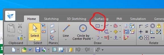
                              Try opening a new metric part and selecting the Draw 'Rectangle by Center' button:

                              sesquaretools.jpg

                              If a plane or face isn't already set Solid Edge asks for one when the drawing tool is first activated.

                              Dave

                              Edited By SillyOldDuffer on 20/09/2022 19:09:25

                              #614895
                              Nigel Graham 2
                              Participant
                                @nigelgraham2

                                Thankyou.

                                It somehow seems the wrong way round at first.

                                I've just tried it – opening SolidEdge, selecting a new Part (metric template)…. I see what you mean, though it took two or three attempts to select the plane I wanted.

                                #615138
                                Nigel Graham 2
                                Participant
                                  @nigelgraham2

                                  Found an intriguing effect (I'd obviously done something wrong!)

                                  No longer really trusting either the tutorials or me, I tried repeating the gist of that journal drawing, but with my own drawing.

                                  The first thing I noticed was that the figure lacked any mid-point markers. Anyway, I planted a simple upright with just a hole though it, on the end of a slab; using dimensions to place it symmetrically; then looked around seeing what if anything might copy it to the opposite end.

                                  The only version of "copy" that appeared to work was Mirror, which I would have wanted eventually anyway.

                                  Unable to control the reflection-axis' location, I moved the reflection to the end of the plate by calculating the dimension-change (surely not the "correct" way?).

                                  That all worked, even if not quite the "proper" technique.

                                  Only..

                                  The original, extruded post had become blended into the base, but I found you need pick the "protrusion" from the little list on the left – I forget the list name off-hand.

                                  Now the oddity.

                                  The reverse-copied entity was neither blended into the base nor "solid". It was a wall, a sort of mummy-case shape with a tube in the semicircular end.

                                  The copy was of the surfaces, not the entire lump.

                                  #615148
                                  SillyOldDuffer
                                  Moderator
                                    @sillyoldduffer

                                    Can you manage pictures Nigel? WindowKey-Shift-S should open a screenshot tool which can save jpgs.

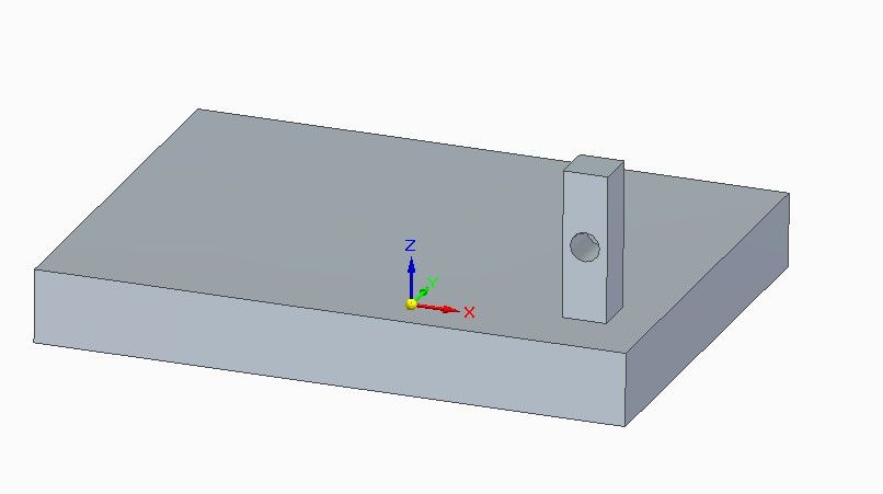
                                    I guess you have an object like this:

                                    nigelsinglepost.jpg

                                    And want to copy the post with a hole in it. First select the feature to be copied:

                                    nigelposthighlit.jpg

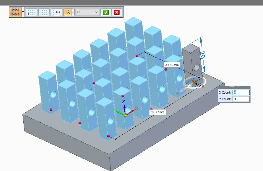
                                    Note the Pattern tools are now activated. These do various ways of copying features in pattern but the most commonly used are within a rectangle or around a circle. I chose the rectangle option:

                                    nigelpost6x4.jpg

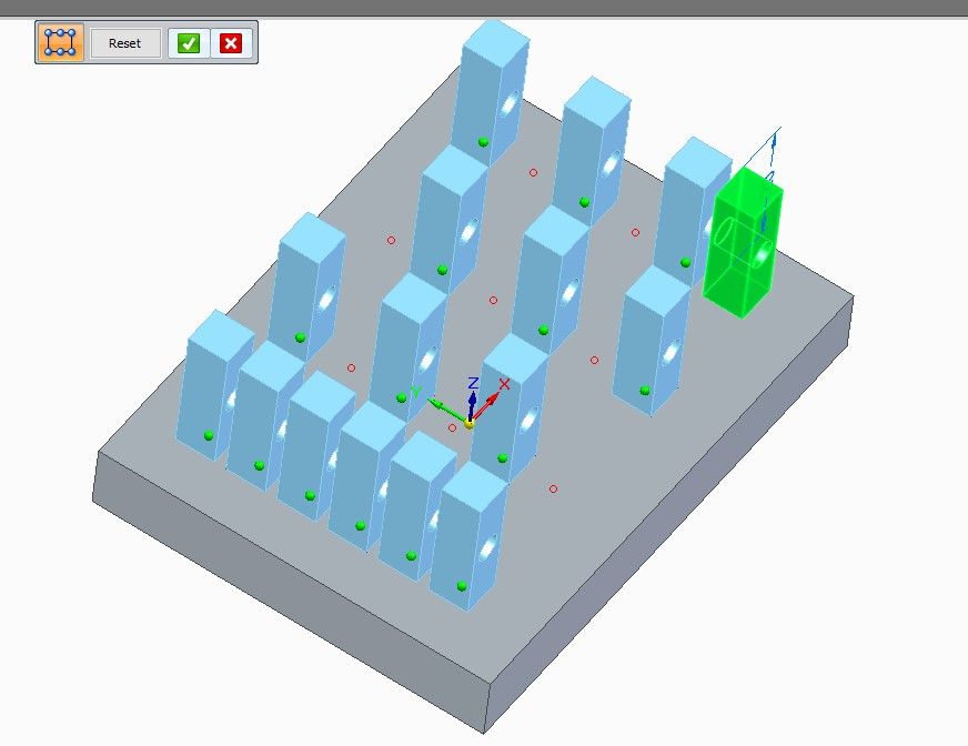
                                    When the tool starts, it waits for the operator to move the mouse to select the copy reference point (yellow dots and wheel) and then the area within which to feature will be copied (red dots). I set the dialog box to show I wanted 6 by 4 objects. This is the first button in the tool bar. The other two allow unwanted copies to be suppressed. Clicking on green suppresses it, clicking on red makes it reappear:

                                    nigelpostsuppress.jpg

                                    Is that the 'copy' part explained? I'm not sure what the other problems are without a screenshot.

                                    I find SE quite fiddly at times, and it took me several attempts to get the pattern tools to work. Logical enough when I finally 'got-it', but not quite how I expected it to work on first contact.

                                    Dave

                                    #615239
                                    Nigel Graham 2
                                    Participant
                                      @nigelgraham2

                                      Thank you!

                                      That's a tool I'd not found.

                                      Ah… I didn't save my odd-looking drawing. I kept the base part, the original file – a rectangular plate like on your examples – but not what I tried to develop on it, because that didn't work as I'd hoped.

                                      It was similar to the exercise "Journal" above, in my first post, but slightly simpler, with no boss and fillets. I'd tried to duplicate the upright part on the opposite side.

                                    Viewing 17 posts - 1 through 17 (of 17 total)
                                    • Please log in to reply to this topic. Registering is free and easy using the links on the menu at the top of this page.

                                    Advert

                                    Latest Replies

                                    Viewing 25 topics - 1 through 25 (of 25 total)
                                    Viewing 25 topics - 1 through 25 (of 25 total)

                                    View full reply list.

                                    Advert

                                    Newsletter Sign-up