Scale model Economy hit & miss engine builders wanted

Advert

Scale model Economy hit & miss engine builders wanted

Home Forums I/C Engines Scale model Economy hit & miss engine builders wanted

Viewing 25 posts - 151 through 175 (of 183 total)
  • Author
    Posts
  • #59821
    Charles 2010
    Participant
      @charles2010
      According to all that I have read and been told the fuel entering a carb should be just below the exit point in the carb ( ie where the needle jet opening is.
       
      So to achieve this the first way is to put a non return valve in the line so that the fuel that is sucked up stays there ready for the next entry into the cylinder.
       
      An alternative is to have a float chamber adjacent to the carb with a needle to stop fuel entering when full
       
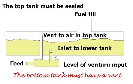
      Another alternative is to use the chicken feed hopper idea where fuel only enters the feed section when previous fuel has been used and allows more fuel to enter


      and lastly a small thin but long fuel tank placed at just below the level of the exit point to the carb.
       
      What you want to avoid is for fuel to have to be sucked up into the carb all the time as the needle jet will need to be open further than necessary for the right amount of fuel to enter the carb and mix with air and this will lead to flooding of the engine.
       
      I understand that the mix must be 14.2 to 14.9% fuel to air for ignition and this must be in vapour and not dropletts. 
       
      An external fuel tank sounds a good idea but at no time must the fuel in the tank be above the exit point of the carb else it will just flow out nor too far below other wise the mix will not be right as the carb has to do too much sucking up of fuel before vapourising.
       
      I hope this has been fo some help you you ..

      Edited By Charles 2010 on 02/12/2010 10:42:39

      Advert
      #59822
      Anonymous
        Hi Charles,
         
        Great stuff, thanks. I think I understand what is going on now. I’m not sure what the percentage of fuel to air is, but I do remember vaguely from my thermodynamics courses that the stoichiometric air/fuel mixture for petrol is approximately 14.7, by mass, for complete combustion.
        I think the best thing to do is make and fit the carb and then design the fuel tank to suit. I’m planning to mount the engine and ancillaries on a square piece of jig plate, so I also have some flexibility on the height at which I mount the engine.
        Regards,
        Andrew
        #59823
        Charles 2010
        Participant
          @charles2010
          Well I was in the right ball park ..
           
          I have Googled and 14.7% is right …  well recalled !!!
           
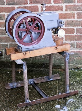
          Here is the stand I built on Tuesday before the “real” snow arrived !!!!
           
           
          It is designed to bring the crank handle to about 24″ from ground level. I may also fit it with wheels.
           
          Regards Charles

          #60369
          Charles 2010
          Participant
            @charles2010
            With all the modifications made to the engine the most necessary one was to the hit and miss action in that I have taken the pushing shaft back so that the push shaft does not exit the rotation shaft until the balls start to fly then as the engine speed up the shaft causes the hit and miss action to take place …
             
            All very satisfying but not caught on video as I was operating all the items my self ..
             
            BUT bad engineering on my part means that a new crank is needed as mentioned before even the pinning has not held things solid so I may try welding the crank ad a temporary measure.
             
            The big eng bearing is also showing slop …  so a new one of those also required …
             
            Still progress has been made and 2011 should see the engine running well …
             
            Thanks for all who have made most useful comments on this forum …
             
            Happy Christmas and good engineering in 2011..
             
            Charles
            #60370
            dixie
            Participant
              @dixie
              Hello Charles 2010
              To make a tapered fuel screw drill down the end of your threaded part then super glue a gramophone needle in job done, look on ebay for needles.
              brian
              #60386
              Charles 2010
              Participant
                @charles2010
                The needle idea sound good.
                 
                I am pleased to say the re-vamped carb is now working very well but now have to work out a way to stop the vibration of the engine causing it to close. Probably I will work out a stop so that is fails to an open position  and not closed position !!
                 
                Regards Charles
                #60412
                MichaelR
                Participant
                  @michaelr
                  Hi Charles,
                  You may have to think about balancing the flywheel on your engine to cut down the vibration, you can do this by removing some weight from the flywheel inner rim and diametrically opposite the crank pin, this can be a trial and error job. As in the picture

                  Edited By Stick on 12/12/2010 11:52:17

                  #60414
                  Charles 2010
                  Participant
                    @charles2010
                    When I have made the new crank in 2011 Then I will be able to set about trying to balance the fly wheels as you suggest. in the mean time may be I can add some weight as done with car wheels !!!
                     
                    Regards Charles
                    #60418
                    JasonB
                    Moderator
                      @jasonb
                      You may also want to think about some balance weights on the crank webs
                       
                      J
                      #60443
                      Charles 2010
                      Participant
                        @charles2010
                        I have been considering why my key ways are not holding the flywheels and I have found this web site ..
                         
                         
                        Looking at the table it seems that the keyways for the Model Economy engine could take  6x6mm keys rather than as the plans suggest 4x4mm keys.
                         
                        Am I reading the table correctly as a 6x6mm key is substantially bigger than a 4x4mm and may be the reason why I am getting s working loose.
                         
                        Any comments please even to say I am totally wrong and 4x4mm is correct.
                         
                        regards Charles
                        #60445
                        Keith Long
                        Participant
                          @keithlong89920

                          Hi Charles

                          My personal feeling id that if the shaft is a suitable size for a 6×6 key then you won’t loose anything by going for the bigger size. From my own (limited) experience with keys in a crankshaft (on a full size car) fit is all important. The key should be a GOOD  snug fit in the shaft as any slackness will eventually lead to the key coming loose and damaging the shaft by fretting. I had this happen on a Peugeot 504 engine. Fortunately I was able to repair the shaft with stainless steel filled Devcon, and changing the pulley that was keyed to the shaft was an easy option. A new key fitted into the shaft with the Devcon, allowed plenty of time to set and 20,000 miles later all was still well. Also how are the other parts held to the shaft. If they can move against the key you are likely to end up with damage.

                          Keith 

                          #60450
                          Charles 2010
                          Participant
                            @charles2010
                            Hi Keith
                             
                            That is most helpfull from your experience and I consider that machining something bigger should be easier on tollerence than the smaller keyway.
                             
                            I have today been making a new key as a better fit than the old one so I will see how that goes first and then have the option of making the key way bigger if it is not an improvement.
                             
                            Regards Charles 
                            #60451
                            Charles 2010
                            Participant
                              @charles2010
                              The other parts are only held on by the key being tapered but I am to use a parallel keyway and grub screw as an alternative.
                              #60456
                              John Olsen
                              Participant
                                @johnolsen79199
                                Hi Charles, A good snug fit is probably the most important factor in getting a key that does not work loose. The main thing against a larger size would be if it starts to look out of proportion. But I think your idea of making a biggerr key to fit the existing keyways first is good, it does not do anything too irreversable and gives you a bit of practice fitting the keys. If it is only a few thou looser than you want, a bit of Loctite will take up the clearance.
                                 
                                regards
                                John
                                #60503
                                Charles 2010
                                Participant
                                  @charles2010
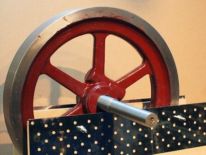
                                  Balancing of the flywheels is completed by using the crude but effective set up. They now rotate right across the 12″ of metal edge  with only a gently push. The holes are driled in the top ede inner side as there was not sufficient material to drill where painted red. Sorry about the paint smudges I will clean then off one day !!!
                                   
                                   
                                  It will be interesting to see if the amount of vibration is reduced when next run.
                                   
                                  Regards Charles

                                   
                                  #60504
                                  Charles 2010
                                  Participant
                                    @charles2010
                                    I have re-thought the keys and I do not think it will be possible to adopt 6x6mm as this may result in failure of the gear on the crankshaft as there is not much metal left with a 4x4mm keys way.
                                     
                                    Regards Charles
                                    #60523
                                    Charles 2010
                                    Participant
                                      @charles2010
                                      Posted by Stick on 12/12/2010 11:51:24:
                                      You may have to think about balancing the flywheel on your engine to cut down the vibration, you can do this by removing some weight from the flywheel inner rim and diametrically opposite the crank pin, this can be a trial and error job. As in the picture

                                      Are you indicating that the balancing should be done to take account of  the crankshaft and the reciprocating weight of the con rod and piston as well as the flywheels or does one balance the flywheels alone ???

                                      regards Charles


                                      #60525
                                      Ian S C
                                      Participant
                                        @iansc
                                        On full size engines it is recomended tha any balance weights should be on the crankshaft, ie., as extentions of the crank webs, rather than putting the weights on the flywheels, that said its not unusual for hit and miss engines like theseto have a flywheel with weight built in. I think its some thing with twisting momenton the shaft.Ian S C
                                        #60527
                                        MichaelR
                                        Participant
                                          @michaelr
                                          Hi Charles.
                                          You have to take in account of the reciprocating weight, as “Ian S C” says one way of doing it is to add counter balance weights to the crank webs.
                                          This sketch shows what I was getting at.
                                          Stick.

                                          #60535
                                          JasonB
                                          Moderator
                                            @jasonb
                                            Just balancing the flywheels will only have a small effect as it only takes out any inbalance in the actual flywheel casting. Balancing the crank as I suggested several posts back will stop the engine moving back & forth as will an alloy conrod over steel and an alloy piston over CI.
                                             
                                            You can either add weight to the crank oposite the pin or remove weight from the flywheel on the pin side which can be done by drilling as shown on the sketch above or milling away the rim to leave a balance weight on the oposite side, I’ll post a pic of the later in a while.
                                             
                                            Edit, pic of the machined balance weights on the IHC Famous I’m currently working on


                                            Jason

                                            Edited By JasonB on 14/12/2010 16:51:58

                                            #60560
                                            Ian S C
                                            Participant
                                              @iansc
                                              You can add weight by drilling the rim, and filling the holes with lead/ solder. once the wheel is painted, no holes, just make sure you tin the holes first, or the lead will eventually come loose. Ian S C
                                              #60660
                                              Charles 2010
                                              Participant
                                                @charles2010
                                                I do appreciate the comments about using the flywheel to balance the crank but it has also been suggested to me that to balance components is also and acceptable method.
                                                 
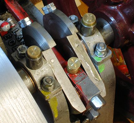
                                                So with that in mind and in the essence of discovery I have decided to extand the webs and use the extensions in an effort to effect balance.
                                                 
                                                First try is shown.

                                                The engine will be run in the morning.

                                                 
                                                Regards Charles
                                                 
                                                #60663
                                                Charles 2010
                                                Participant
                                                  @charles2010
                                                  Now here is an interesting distilation of a discussion I had this morning:-
                                                   
                                                  Balancing a single cylinder engine.
                                                  I have been told by a friend’s at the Bredgar and Wormshill Light Railway that it is a fact is that it is IMPOSSIBLE to balance a single-cylinder engine. The best that can be done is a compromise.

                                                  This is the suggestion :-

                                                  Locate a set of digital scales.
                                                  Take apart the crank assembly, then with the top half (little end) in your hand level with the scales weigh the bottom half of the rod call this BCR.
                                                  Now take the big end in your hand and weigh the top half of the rod call this TCR. 
                                                  Now weigh the piston and all that goes with it call this P.
                                                  Add the weight of the top half of the rod to the weight of piston which is TCR + P.
                                                  Now you need to assess 65% of this weight which is 65(TCR + P)/100.
                                                  Add this weight to BCR and machine a piece of material to this weight to fit over the crankpin thus {65(TCR + P)/100}+BCR
                                                  Now you need to make weights that balance the crank shaft.
                                                  That is the best one can achieve.

                                                  I am guessing that if you weighed the big end of the crank with the mass attached it would give one a starting point as to the mass required.
                                                   
                                                  I know I am re-inventing the wheel  but this is what the chaps must have done years and years ago (1910 ??)
                                                   
                                                  Has anyone tried this or seen the similar set of instruction on the web
                                                  http://www.prestwich.ndirect.co.uk/technical_balancing.htm as I saw this afternoon and it matches almost exactly what I was told (may be it is a standard practice)?
                                                  #60667
                                                  John Olsen
                                                  Participant
                                                    @johnolsen79199
                                                    Charles, you are right, it is not in fact possible to balance a single cylinder engine by simply adding balance weights. Ignoring the effects of connecting rod length, when we add balance weights we are trying to balance a reciprocating motion with a rotating one. If the balance weights are big enough to balance out all of the reciprocating mass, we end up with an out of balance force just as big, but at right angles to the original. eg for a horizontal cylinder, we could balance out all the horizontal out of balance force, but would end up with a vertical one just as big.
                                                     
                                                    So practically we only try to balance out part of the force. The best factor to use actually depends on the mountings of the engine and the way it is used…65% used to be not uncommon for single cylinder motor bikes, where a horizontal out of balance force is often preferable to a vertical force, but plenty of other factors were used. Anything in the range around 50% is worth a try. There is no one general ideal factor for all cases, although for any given case there will be a best compromise. For bikes, fiddling with the factor can make it better at a chosen cruising speed, at the expense sometimes of being worse elsewhere. A typical single cylinder motorcycle can have an out of balance force of the order of 1 ton or so, or about 10,000 Newtons for the purists
                                                     
                                                    We can of course balance all of the rotating masses, so the resulting balance weights will balance all of the rotating mass, including the rotating component of the connecting rod, and some part, around the 50 to 65% range of the reciprocating masses. For the kind of engine under discussion this is not going to be too critical, for a motorbike it can be the difference between a pleasant ride and numb feet. Steam engines often make no attempt at all, but at low speeds this is no problem.
                                                     
                                                    The balance weights should be equally disposed either side of the piston, as otherwise we will introduce a rocking couple. This should not be a problem with a twin flywheel engine, or with one where the weights are on the cranks.
                                                     
                                                     
                                                    regards
                                                    John
                                                    #60668
                                                    Charles 2010
                                                    Participant
                                                      @charles2010
                                                      Thank you for confirming what I was told today …
                                                       
                                                      It is so nice when ideas are confirmed and one is not then totally in the dark going forwards.
                                                       
                                                      I was told about the 90 out situation but did not fully comprehend it until your explanation clarified it for me.
                                                       
                                                      I will take into account your comments on keeping things balanced each side of the piston something I had not thought about..
                                                       
                                                      Below is the link to a short video of the engine runing as of 14th but it wil be tried again tomorrow with the experimental balance weights and I hope also take some video.
                                                       
                                                       
                                                      Regards Charles
                                                       
                                                       
                                                    Viewing 25 posts - 151 through 175 (of 183 total)
                                                    • Please log in to reply to this topic. Registering is free and easy using the links on the menu at the top of this page.

                                                    Advert

                                                    Latest Replies

                                                    Home Forums I/C Engines Topics

                                                    Viewing 25 topics - 1 through 25 (of 25 total)
                                                    Viewing 25 topics - 1 through 25 (of 25 total)

                                                    View full reply list.

                                                    Advert

                                                    Newsletter Sign-up