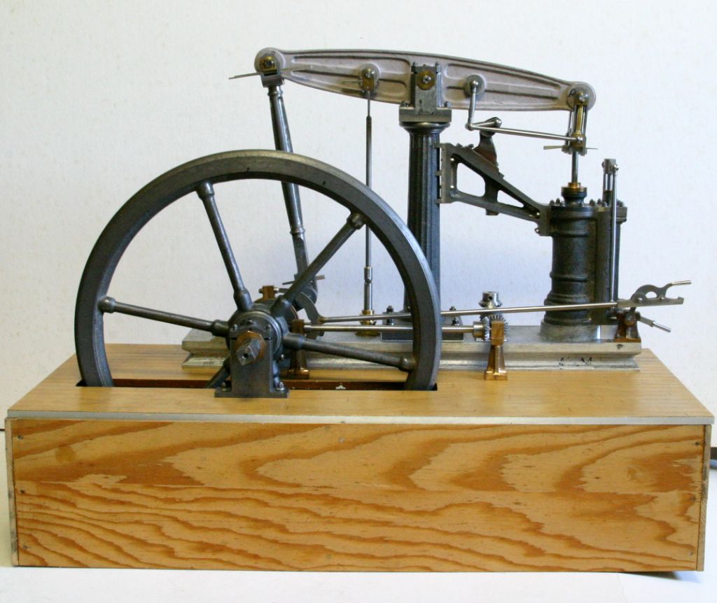
The Sanderson is almost finished, just a few 1-72 (10BA ) studs and the governor to do, and finish off the base with some tiles to simulate stone work.

I finally got the governor drive gear train to run reasonably smoothly after a lot of trial and error. As mentioned in my post in "Help and Assistance Wanted" titled "Sanderson Gears" (07/10/22 ) the 3:1 drive gears will only run if the pinion is backed out of full engagement with the crown gear and is set with a fair bit of backlash. Also a fair amount of lapping them together helped them run smoothly. The mitre gears were a different story.

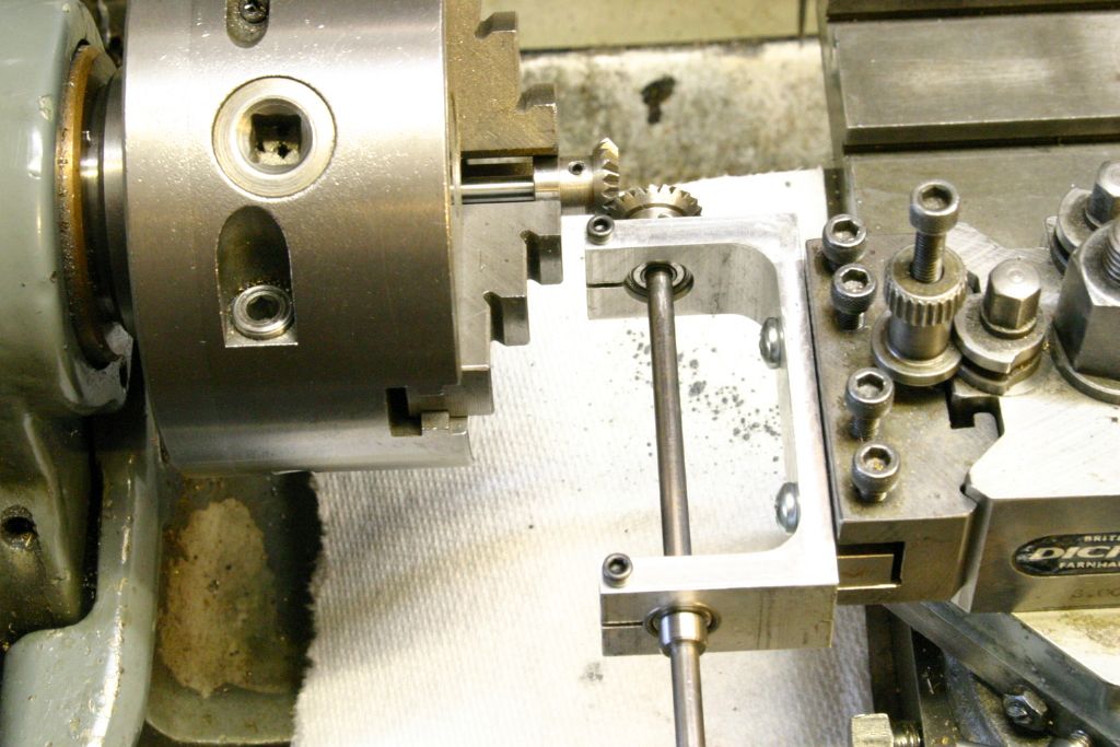
I used this jig to check the mesh and also to lap them together. The two 3/16" dia. shafts run in R3 ball bearings, and with the top slide set at 45 degrees the mesh of the pair can be adjusted. They are rotated by twirling the shaft of the unit on the top slide between the fingers. I tried various combinations of the 4 to find the best 2 pairs. On one of the pairs the teeth on both gears came to a point (can be seen in the picture in other post ) and when the gears were meshed and held up to the light appeared to be bottoming in the gullets of the opposing teeth with the flanks not touching. I therefore set them up in the lathe on a true running mandrel, and with the top slide set over to 45 degrees skimmed the tips of the teeth to leave them with a small flat. That improved things considerable. I also thought their width was wider than necessary, so I machined .060" off the front face to make them narrower. That again improved their running plus I think they look much better.
That was followed by an extensive period of lapping each pair together, with every once in a while disengaging them and rotating one gear by one tooth space and re-engaging them to continue lapping. I figured I should do this as with the same number of teeth on each gear the lapping would then average out and they should engage the same no matter how they were meshed. That sort of worked as there is one orientation where they run best

In the end I have ended up with a gear train that runs reasonably smoothly although has a little more backlash than would be normal hence is a little noisy.
I figured it would be next to impossible to line up and set the mesh of the gears by clamping down and spotting through the holes in the base of each of the three shaft bearing supports for studs and nuts so I cheated a bit and drilled and tapped a hole in the bottom of the base of each and after clamping them in position for the best mesh of the gears I marked their position on the base plate and drilled an oversized clearance hole for a single hold down screw up from the bottom. This allowed for some adjustment of position to get the smoothest running. I'll fill the holes in the bearing standards with dummy studs and nuts.
Now for the governor itself I'm not sure what I will do, as I've said previously that section of my plans (original Clarkson's dye line ) have faded to the point where they are unreadable. I have the plans for two other beam engines, "Mary",and "Lady Stephanie" also Anthony Mount's "Scotch Crank Engine" which all have governors. So barring getting the Sanderson drawings I should be able to figure something out using those three.
John
Edited By John Purdy on 18/08/2023 00:28:48
 John Purdy.


