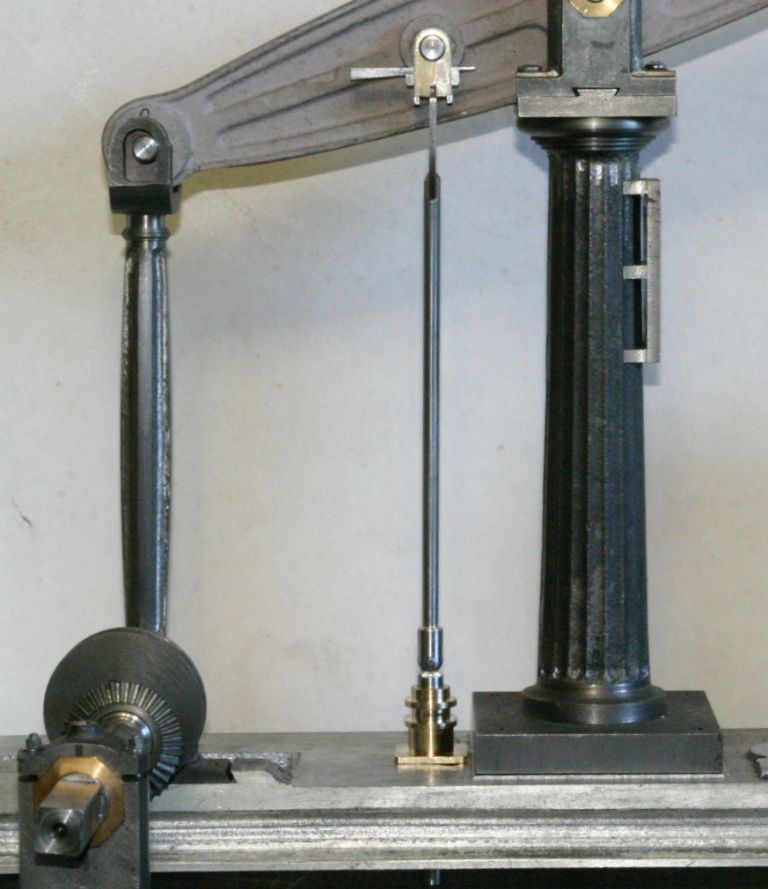
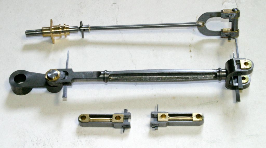
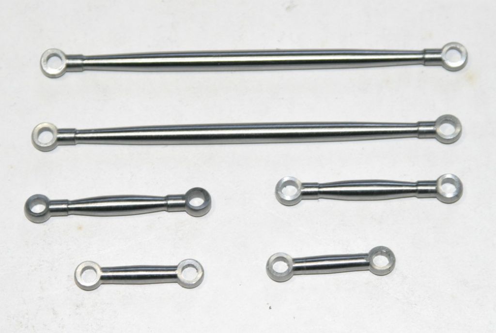
Finally finished the con rod, pump rod and the strap links connecting the piston rod to the beam. So it's time to stop procrastinating and tackle the parallel motion links.

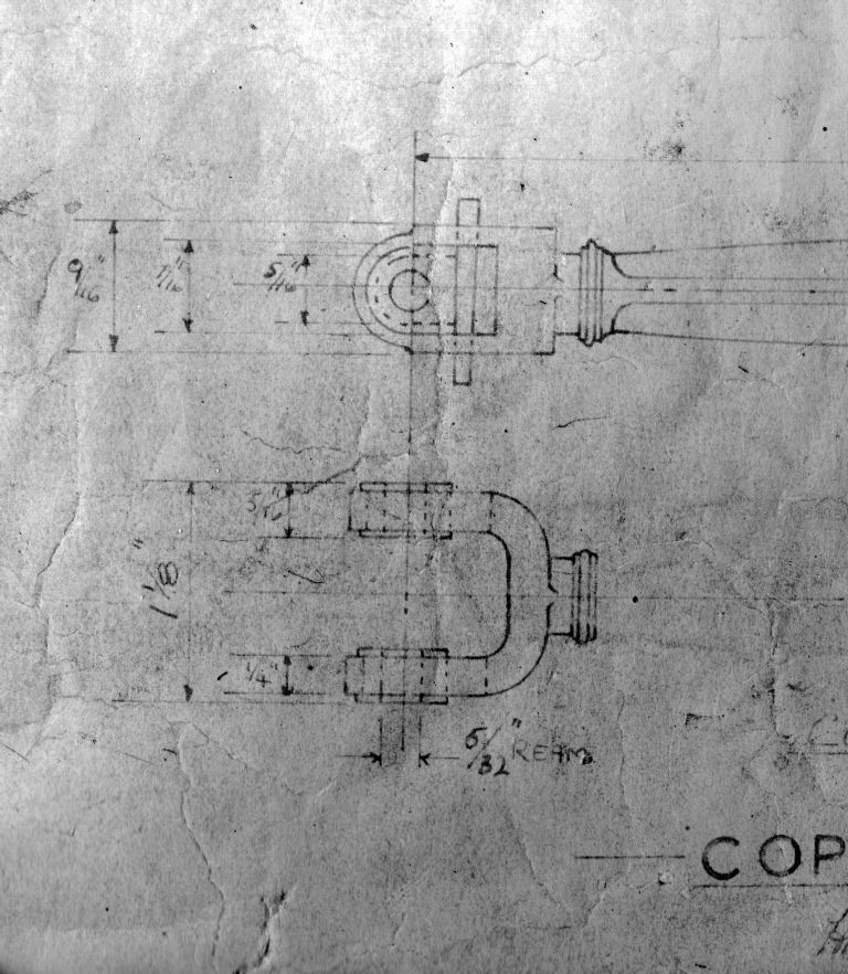
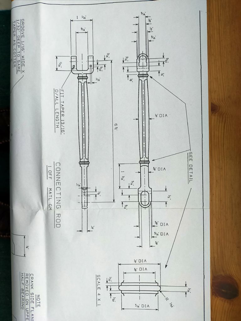
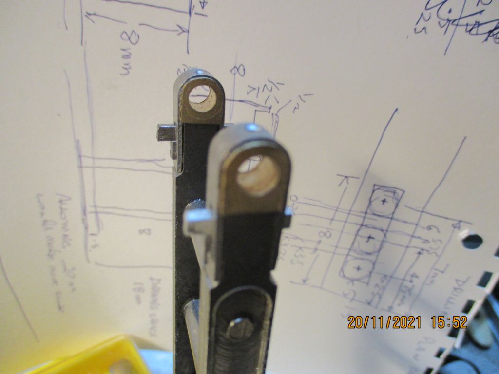
The plans show the links with 7/32" dia. spherical ends thinned down to 1/8" thick and the body fish bellied 5/32" in the middle and 3/32" at each end with a short parallel section 1/8" dia before the spherical end. Question is how to make then. If the centre section is turned first then how to hold it to turn the ends seeing as how the there is nothing parallel to hold. If the ends are turned first then how to hold it to turn the fish bellied centre section?
After considerable head scratching I came up with this idea. Starting with 1/4" dia. rod, drill and ream the two 1/8" end holes using coordinates in the mill, spaced .109" in from each end. Use a form tool to turn the spherical ends and the short 1/8" parallel section. Now the centre section can be turned by holding the left hand end in a specially made jig on the end of a piece of 1/2" square material held in the 4 jaw with the right hand end supported in a small female live centre in the tail stock.
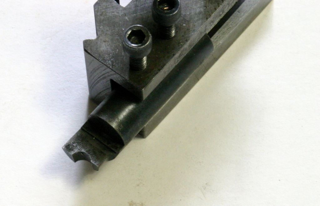
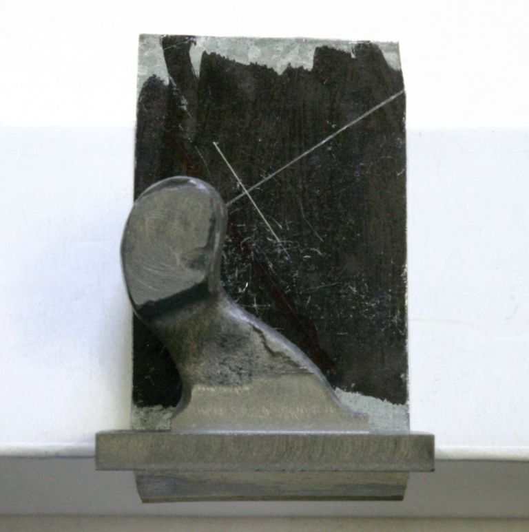
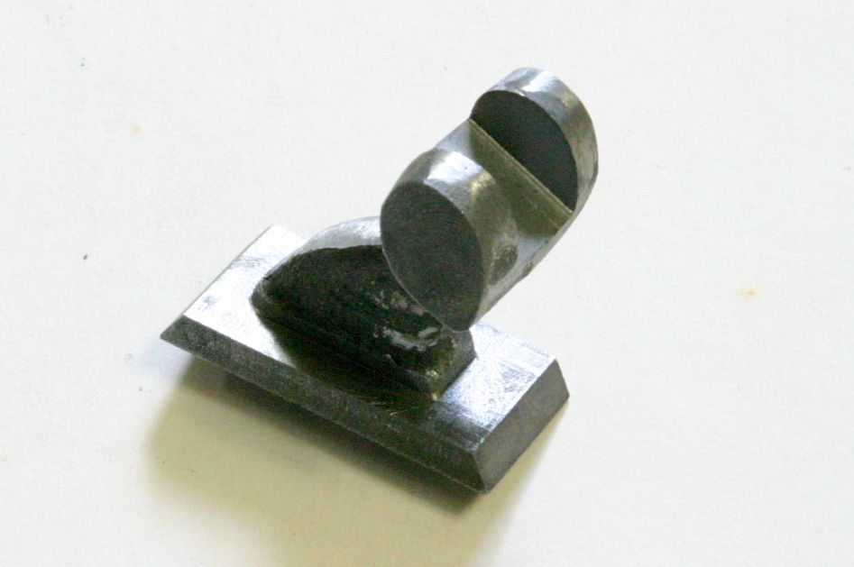
The form tool to turn the spherical ends of the links was made from a piece of 1/2" W1 drill rod. Held in a 5C collet in a collet block and set at a 3 deg. angle in the vice the end was milled down to half dia. This gives some back rake to the cutting edge. The collet block was then re-positioned at a 7 deg. angle to give the front clearance and a 7/32" end mill was used to angle the front edge and then, on the centre line, plunge down for a further .109" to form the half circle cutting edge for the ball. The ear, on what would be the chuck side when used, was milled back to leave it .047" from the centre of the 7/32" dia. ball to form the 1/8" dia. collar.

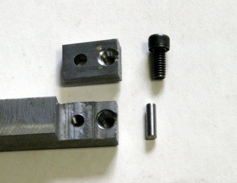
The jig to hold the end of the link in the 4 jaw was made from a piece of 1/2" square steel from the scrap box with the end milled down to 1/4" for 11/16". Dimples were made in it and the cover, 1/8" in from the end, with a 1/4" 90 deg. spotting drill followed by a #3 (1/4" ) centre drill. The depth was adjusted so the link longitudinal centre line was on the centre line of the 1/2" bar. An 1/8" end mill was used to cut a slot .060" deep on the centre line into the dimples to provide clearance for the 1/8"dia. collar on the link. The central hole was drilled through and reamed 1/8". The two pieces were clamped together with an 1/8" rod through the central holes for alignment and drilled and tapped for an 8-32 screw to clamp them together. The pin is an easy fit in the 1/8" holes in the jig and link to provide some clearance for alignment and to provide a positive drive. It is retained from falling (flying ) out by thin sheet strips riveted to outsides of the two pieces.

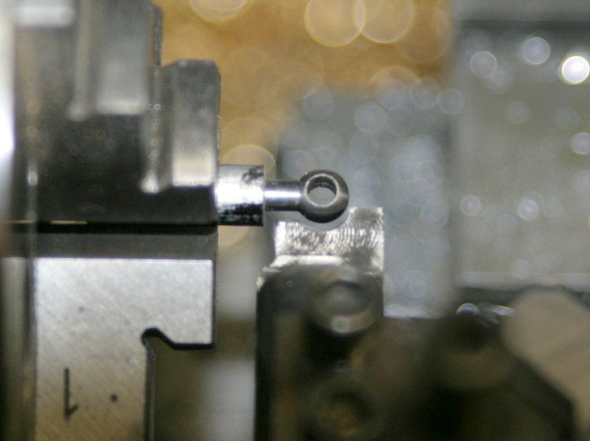
One eye turned on the end of an embryo link with the form tool.

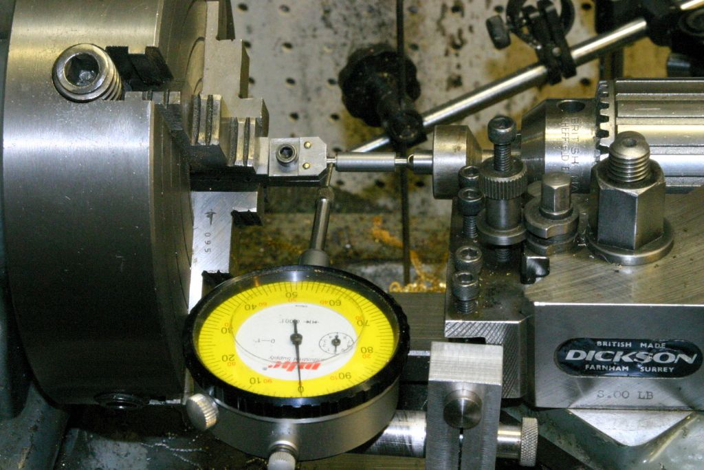
Using a dial indicator on the 1/8" dia. collar to centre the link held in the jig in the 4 jaw. The other end supported by a small female live centre in the tail stock. The female live centre held in the drill chuck is a Unimat live centre modified by disassembling and pressing the male centre out of the bearing and pressing in a home made small female centre .

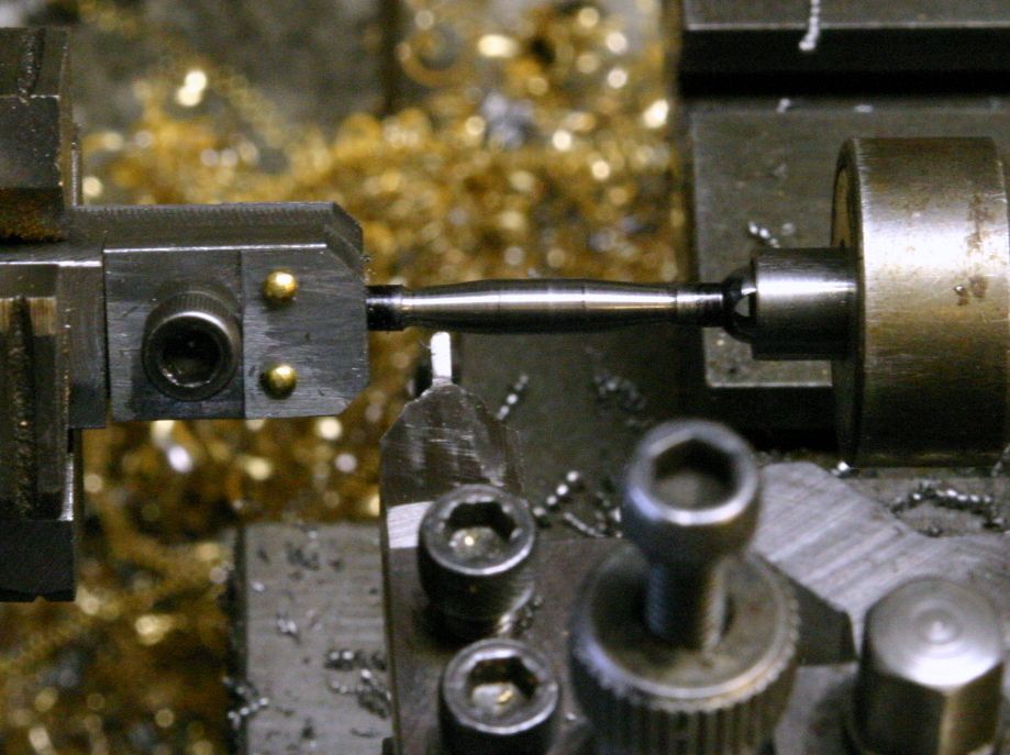
The centre fish belly roughing out finished. Just needs some work with a fine file to blend the flats together and polishing with some fine abrasive cloth.

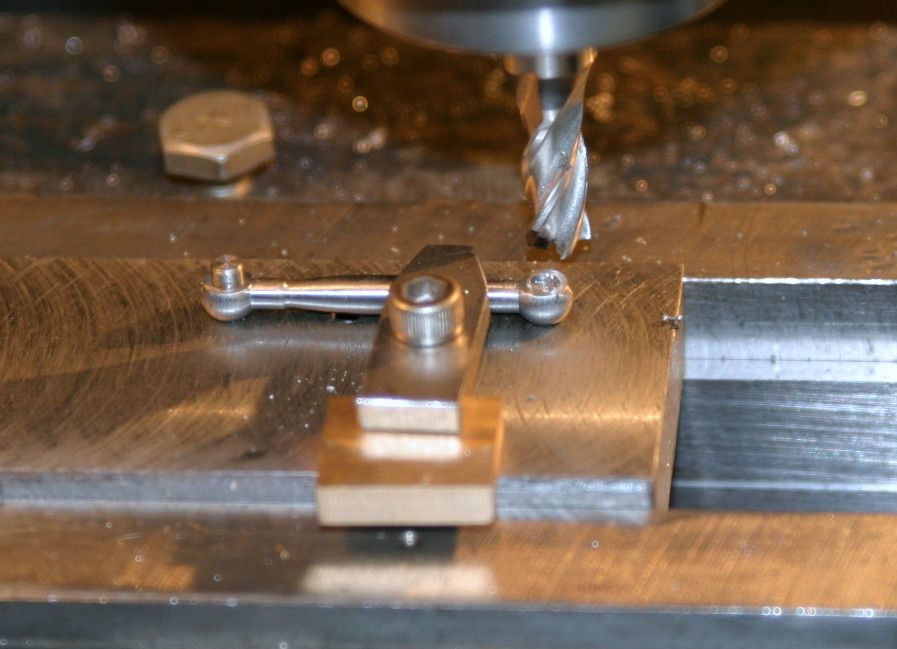
The jig set up in the mill for machining the eyes down to 1/8" thick. The jig isn't my idea, it's from Tubal Cain's write up in ME of the "Mary" beam engine. The clamp is my addition and is done up just finger tight to prevent the possibly of the link moving up under the milling forces.

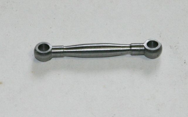
A finished link. Only 7 more to go!

Edited By John Purdy on 14/05/2022 02:22:13
Edited By John Purdy on 14/05/2022 02:29:34
 John Purdy.


