Rumely Oil Pull engine

Advert

Rumely Oil Pull engine

Home Forums I/C Engines Rumely Oil Pull engine

Viewing 25 posts - 1 through 25 (of 66 total)
  • Author
    Posts
  • #501860
    John Rutzen
    Participant
      @johnrutzen76569

      Hi, I'm working on the design for an engine for a Rumely tractor that I want to build. There are no drawings but I have got the major dimensions from an owner in America. I am working out the engine from photos, catalogues, videos and anything else I can get hold of. It is a single cylinder 30cc. What I want to ask is can i fit a C.I. liner in an aluminium block? Also I am thinking of posting the drawing before I make anything for constructive criticism please. I don't do CAD so I'm not sure how I can do this. Maybe just take a photo of it, i'll see how it works out.

      Advert
      #2594
      John Rutzen
      Participant
        @johnrutzen76569
        #501874
        Henry Brown
        Participant
          @henrybrown95529

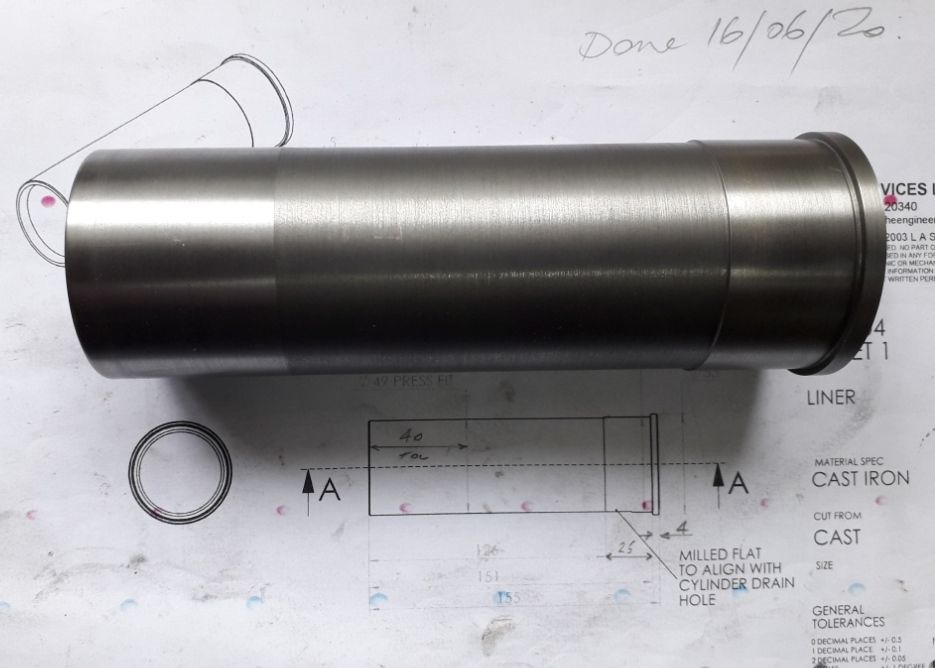
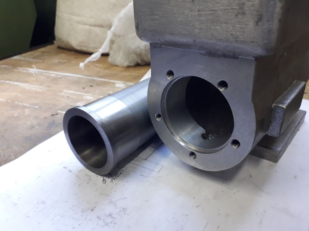
          My Economy Engine from The Engineers Emporium has an aluminium block with a CI liner so I see no reason why not, the block is relieved in the centre so give location at either end of about 30-40mm and has a small flange at the head end for the gasket to seal. I made mine a very slight interference fit and ran a drop of Loctite 638 around each end before using my press to fit the liner. Incidentally the piston is from HE30 bar. I'll see if I can find a picture fo the parts before I assembled them.

          Looking forward to seeing the drawings and the end results!

          #501877
          Henry Brown
          Participant
            @henrybrown95529

            Forgot to add the bore and stroke is 42mm x 73mm and the locating diameters (polished) are 49 and 50mm diameter for easier assembly.

            20.06.16 liner.jpg

            20.06.21 hopper and liner head end.jpg

            #501901
            John Rutzen
            Participant
              @johnrutzen76569

              Thanks Henry, I was sure I had seen iron liners in alloy blocks somewhere. Of course I know it is used full size all the time. Is yours a wet liner, meaning the water is in direct contact with it.  

              Edited By John Rutzen on 17/10/2020 15:15:49

              #501931
              Henry Brown
              Participant
                @henrybrown95529

                My pleasure, hope it has helped. Yes, its a tradition engine with water in the hopper surrounding the liner in the area between the fitting diameters, that's why I used the 638 as a bit of a safety belt. If you use 638 just be aware you only get one go at it as it goes off very quickly, I'll use one with a longer cure time when I make my next one!

                #501935
                John Purdy
                Participant
                  @johnpurdy78347

                  John

                  E. T. Westbury's Wyvern horizontal engine has a CI cylinder liner shrunk into an aluminum block/water jacket and works fine, at least in mine. If I recall I made the liner .001-.002 larger than the bore of the block then to assemble I heated the block in the oven to about 400F and put the liner in the freezer. The liner just dropped in with no problems.

                  John

                  #501939
                  JasonB
                  Moderator
                    @jasonb

                    I've done 3 or 4 open crank ones with CI liner in alloy and even more Ci in CI all a firm push fit and 648 Loctite which makes for a less stressful time joining them together. Like Henry, a step of a few thou in diameter allows the liner to easily slip most of the way in before things start to tighten up.

                    #501955
                    John Rutzen
                    Participant
                      @johnrutzen76569

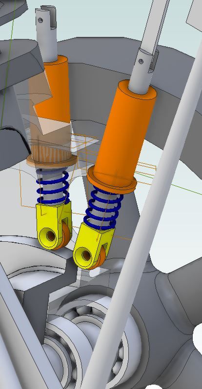
                      Thanks everybody. I've used that 638 and you really have to be quick about putting it together. Maybe you have a minute, no more. I will get some 648 for this. One of the odd things about the Rumely engine is that it has pull rods rather than push rods so there must be some means of holding the rod against the cam. I am still trying to work it out.

                      #501967
                      JasonB
                      Moderator
                        @jasonb

                        Does it use a traditional "cam" shape as we know it or an eccentric? maybe a combination off the two with a strap around a cam shape so it makes contact on the far side of the rod's end and pulls it.

                        Another possibility would be a simple spring between cam follower and rod guide.

                        cam follower.jpg

                        Edited By JasonB on 18/10/2020 07:38:57

                        #501969
                        John Rutzen
                        Participant
                          @johnrutzen76569

                          Hi Jason, here is the link to the only video I've found of it running that shows the inside of the crankcase and the camshaft.

                          Hope you can find that, for some reason it won't come up as a link.

                          #501970
                          JasonB
                          Moderator
                            @jasonb

                            I'll need to study that a bit more but it looks like the rod is being pushed by the cam and then acting on a bell crank which gives the lifting action rather than pushing down on the valve camera cuts away too soon.

                            #505630
                            John Rutzen
                            Participant
                              @johnrutzen76569

                              Hi Jason,

                              I've incorporporated a bell crank into one of the valves and a lever into the other. I would like to use an aluminium alloy cylinder head because I have lots of block of a suitable size. I am basically following E T Westbury's engine design for his road roller where I can. He uses a caged inlet valve and the exhaust valve is seated on the cast iron head. Do you think I could use a bolted on bronze inlet valve cage and loctite a bronze valve seat into the aluminium head? I thought bronze would be better than iron or steel because its' coefficient of expansion is closer to that of the aluminium.

                              Edited By John Rutzen on 06/11/2020 17:27:09

                              #505653
                              JasonB
                              Moderator
                                @jasonb

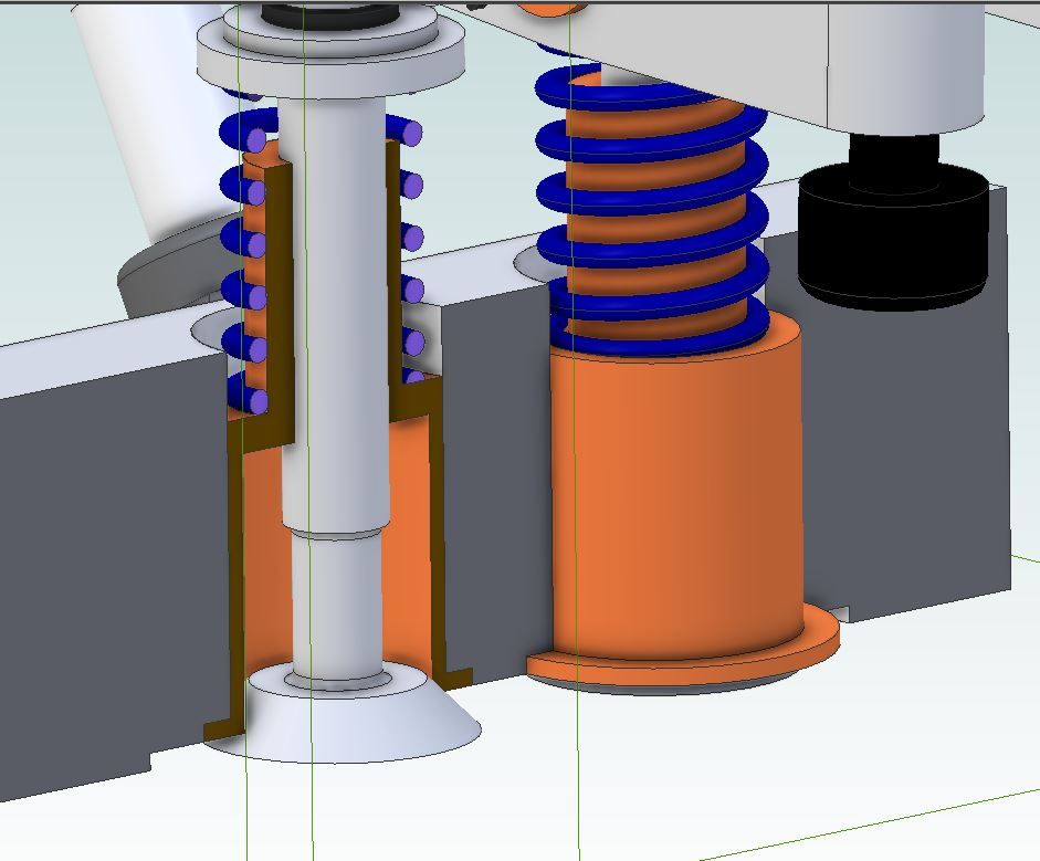
                                You could make the seat and cage all as one and have it a light press fit from the inside adding a drop of 648 Loctite for good measure. Exhaust passage is drilled once cage is in place. This is how the Nemett engines are done.

                                valve cage.jpg

                                #505853
                                John Rutzen
                                Participant
                                  @johnrutzen76569

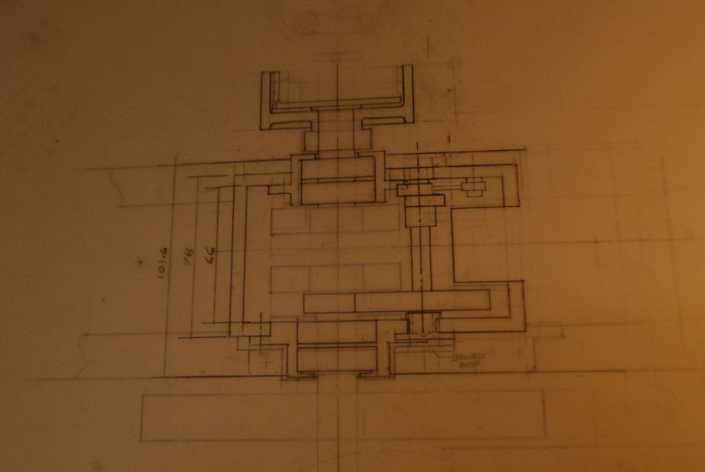
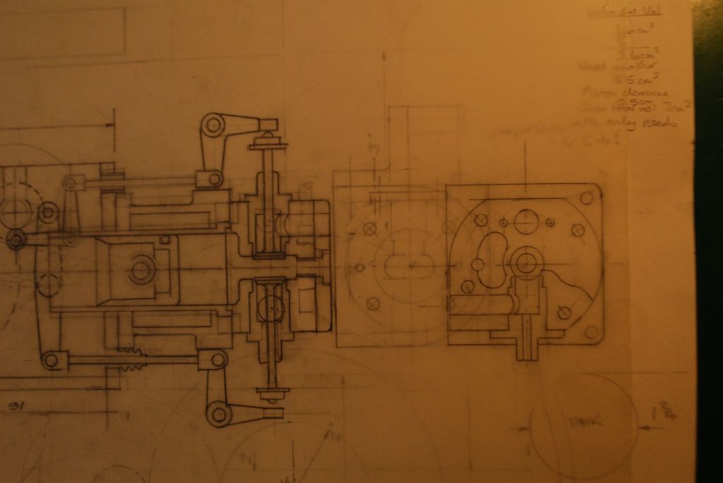
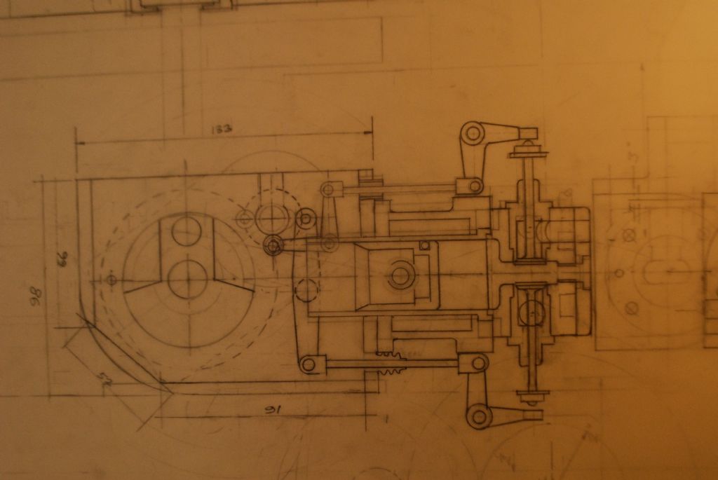
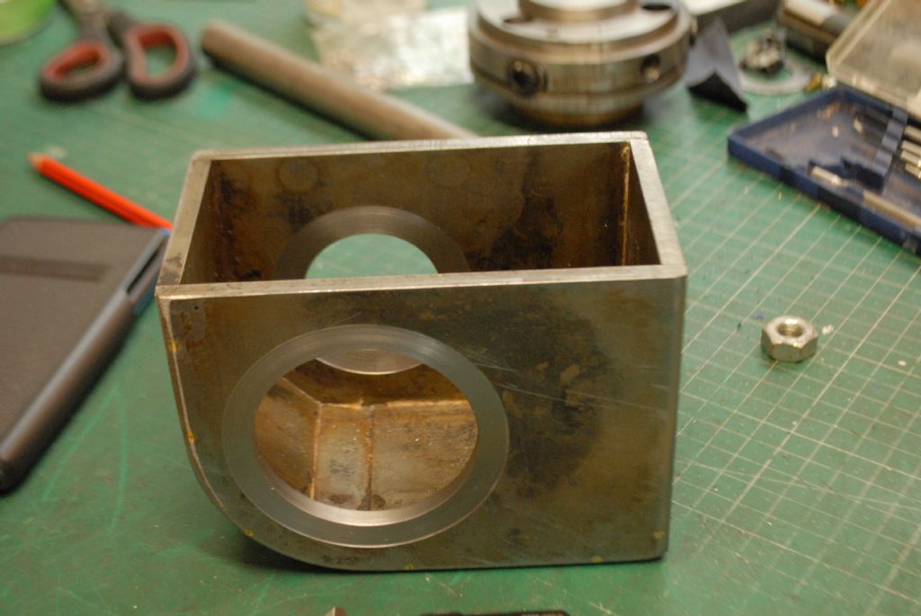
                                  dsc_0053.jpgdsc_0052.jpgdsc_0051.jpgThanks Jason,

                                  i'm uploading some photos of the drawings here and one of the fabricated crankcase that I've just made. I found that 6mm steel is very difficult to heat up enough to silver solder it [with propane]. Much harder than copper and I've made a 5 inch gauge boiler.

                                  dsc_0047.jpg

                                  #505854
                                  John Rutzen
                                  Participant
                                    @johnrutzen76569

                                    Sorry the drawings aren't great but I hope you can get the general idea of the valve arrangement. I tend to draw full size and scale parts off the drawing. Hopefully I'll learn CAD one day but I find drawing much quicker.

                                    #505865
                                    JasonB
                                    Moderator
                                      @jasonb

                                      Drawings are clear enough to see, those bronze cages should be fine. Crankcase is looking good too.

                                      #505889
                                      John Rutzen
                                      Participant
                                        @johnrutzen76569

                                        Thanks Jason, I appreciate your input.

                                        #506662
                                        John Rutzen
                                        Participant
                                          @johnrutzen76569

                                          Hi, I'm trying to work out how to make the cylinder liner and piston for my engine. I've read E T Westbury's articles which say lapping is necessary but I understand that it's possible to use a viton O ring instead of piston rings and having never made piston rings I like that idea better. My question is how to finish the bore for the O ring and how to finish the piston to suit. Both will be cast iron. Thank you.

                                          #506715
                                          JasonB
                                          Moderator
                                            @jasonb

                                            I just use a brake cylinder hone to finish the CI bore and the piston is as it comes off the lathe. You don't want a lot of squash of the rings and a single Viton one will do.

                                            #506766
                                            John Rutzen
                                            Participant
                                              @johnrutzen76569

                                              Thanks Jason, I was looking on eBay for a hone and they seem to be about £7 to £12 . I know nothing about them so is there anything to look out for when buying one? The cylinder bore is 30mm so what section O ring would you recommend?

                                              #506783
                                              JasonB
                                              Moderator
                                                @jasonb

                                                I don't think mine are anything special about the £10mark sounds right, 3 stone at that size.

                                                For 30mm I would say you could go with a BS120, 3.12mm wide groove and 2.5mm deep

                                                #506832
                                                John Rutzen
                                                Participant
                                                  @johnrutzen76569

                                                  Thanks Jason, I'll get one ordered.

                                                  #509773
                                                  John Rutzen
                                                  Participant
                                                    @johnrutzen76569

                                                    I have a query regarding the fitting of the ball bearings on my crankshaft. I was going to fit the outers in the housings using loctite bearing retainer but i want to ensure that the inners don't creep on the crankshaft. Or am I being a bit pernickety? I would have liked them a bit tighter than the fit I achieved but perfection is rarely attained in model engineering so I wondered if there is anything I could put on the shaft that would prevent rotation but still allow me to dismantle it easily. The ball bearings are doubled each side and are 17x 35×10.

                                                    #509793
                                                    Howard Lewis
                                                    Participant
                                                      @howardlewis46836

                                                      Thinking about "Pull Rods" for the valves, how about a lever follower, under the cam. with a refined form of clevis on the pull rod?

                                                      Was that how the real engine did it?

                                                      Otherwise, the spring arrangement shown provides the opening force for the valve by keeping the follower in contact with the cam. and then if the linkage is secured to the valve, as a valve spring to hold it on the seat..

                                                      Or was the cam internal, with the pull rod external to the follower?

                                                      Howard

                                                    Viewing 25 posts - 1 through 25 (of 66 total)
                                                    • Please log in to reply to this topic. Registering is free and easy using the links on the menu at the top of this page.

                                                    Advert

                                                    Latest Replies

                                                    Home Forums I/C Engines Topics

                                                    Viewing 25 topics - 1 through 25 (of 25 total)
                                                    Viewing 25 topics - 1 through 25 (of 25 total)

                                                    View full reply list.

                                                    Advert

                                                    Newsletter Sign-up