Rotary table stops

Advert

Rotary table stops

Home Forums Workshop Tools and Tooling Rotary table stops

Viewing 24 posts - 1 through 24 (of 24 total)
  • Author
    Posts
  • #54259
    Spurry
    Participant
      @spurry
      Does anyone have any ideas they are willing to share for rotary table stops. The table markings are very clear, but disappear when covered in coolant!
       
      I have to round off 16 corners in 1/2″ steel so thought some stops to restrict the table movement to 90° would be useful. The groove around the circumference is parallel sided.  My only idea to date is to axially drill the bottom of the groove, at say 10° intervals to hold some stops.
       
      I have a feeling there may be a simpler solution….
       
      Thanks
       
      Pete
      Advert
      #16569
      Spurry
      Participant
        @spurry
        #54260
        KWIL
        Participant
          @kwil

          Cut it dry, (this is not intended to be facetious). There are many operations that do not need fluids if you use the correct speeds and cuts (as well as the correct cutters in some cases).

          #54262
          Geoff Theasby
          Participant
            @geofftheasby
            If your table has four T-slots, you could make an insert to allow the table to rotate 90 degrees before hitting an external stop.   If this stop is moveble to anywhere on the lathe bed or milling table, then your 90 degrees could start and stop anywhere.   A powerful magnet, for instance.
             
             
            #54270
            Spurry
            Participant
              @spurry
              Thanks for the replies.
               
              Kwil – I have found that a better finish can be obtained with coolant. Perhaps that’s just me.
               
              Geoff – I should be so lucky. My table has 6 slots. I did post a picture in the gallery, but did not actually achieve the insertion into my posting.
               
              On my last ‘rotary’ job, I overturned the table by a few degrees and had to stick a bit of metal back.   This job highlighted the requirement to do the job properly with some stops.
               
              Thanks again
               
              Pete
              #54278
              Ramon Wilson
              Participant
                @ramonwilson3
                Hi Pete,
                I don’t know if his will be of help but I modified my MES rotary table for stops some time ago
                 
                I cut a tee slot into the edge with two slotting lathe tools and made curved stops.
                The stop block is a piece of cast let in to the base. Work very well indeed and solves the problem of counting turns, marking with felt pen, and of course the coolant problem but like KWIL  I usually cut dry or use coolant applied with a brush – depends of course on what you are cutting and at what rate. Whatever these couple of pics may be of help …….


                Hope they are of use – good luck
                Ramon

                #54287
                Spurry
                Participant
                  @spurry
                  Thanks for those ideas Ramon. That’s a proper job!
                   
                  I’m a little apprehensive about mounting the 10″ table on the lathe to cut the grooves. It sounds very scary to me. Radially drilling on the mill does not seem quite so onerous.
                   
                  Those pictures show me what I ought to do.
                   
                  Pete
                  #54300
                  Ramon Wilson
                  Participant
                    @ramonwilson3
                    Ah Pete you have a point but I did remove the table first and it is only 6″ dia!
                     
                    I would have thought that drilling and tapping a series of holes in the periphery for two screw in pegs which could then have a fixed bar with adjustable stops either side between them would do the same thing. The mods above slowly ‘evolved’ – the fixed bar was fitted first and for some time the ‘stops’ were a pair of toolmakers clamps ‘strategically’ placed. A pain at times but it worked for quite a while before finally a job arrived that needed proper stops.
                     
                    Regards – Ramon


                    #54301
                    Billy Mills
                    Participant
                      @billymills
                      Pete,
                      Fit 4 pointers at 90 degrees apart around the top of the table – could be a square disk with the centre removed and bolted to 3 slots. Line up a post with one corner at 0 degrees. Note the position of the handle then turn a whole number of turns from one corner to the next- don’t count the turns, the 4 corners do it for you, always stopping in the same handle position. If your drive is a multiple of four – 40,60 or 90 turns to 360 degrees  then the coarse corner pointer will always get you to 90 degrees.
                       
                      I use a square or hexagon with the worm out of drive and a lever with two  points of contact with the indexing shape. You slacken the lock then rotate the square (or hexagon) until the lever has two point contact with the next face of the square ( hex), lock it up and machine away.
                       
                      Recently I had to mill four flats at 90 degrees in a 4mm brass rod. The rod was held horizontally in a vee jaw vice and a squared off knob slid onto the brass rod on the other side of the jaws. A lever was arranged to fall onto the flats of the square knob. After milling the first face the vice is slackened and the knob rotated to the next position , vice tightened and next flat milled. Worked well enough for the hundred items with 4 flats at approx. 90 degrees.
                       
                      There is always the option of covering the scale marks up when you are machining then uncovering to get the next position…….
                       
                      regards,
                      Alan
                       
                      Continue to be impressed by Ramon’s beautiful work.
                      #54317
                      Spurry
                      Participant
                        @spurry

                        Posted by Alan Gray 1 on 15/08/2010 00:13:20:>>

                        Continue to be impressed by Ramon’s beautiful work. >>

                         >>

                         >>

                        You and I both.


                        Thanks for the tips Alan. That’s very useful for machining flats. My particular problem is with machining radii and slightly overcooking the turning when continuously machining the curve.


                        Ramon – What sort of  size of T slot would you machine? I gues a minimum would be about 2mm deep at the top (bottom?) of the T, perhaps 3mm with a suitable tool. My parallel sided slot is  10mm wide x 9mm deep at present..


                        Thanks again


                        Pete

                         >>

                        Edited By Spurry on 15/08/2010 13:19:12

                        #54330
                        Ramon Wilson
                        Participant
                          @ramonwilson3
                          Hi Pete just seen this – been and measured it …
                           
                          The slot is 8.1  deep from the outer face. The width is 5.8.
                          The ‘tee’ width is approx 11 and the top flange (?) is 4 thick.
                           
                          The tee nut is 10.7 wide by 20 long with the upstand 5.7 wide and 3.9 high. the base (tee width) is 3.3 at it’s widest part
                           
                          The inner most part of the tee nut is flat but the outer and bearing  faces are curved to match the radii of the slot and outer diameter.
                           
                          The stop blocks are just machined to the same radius as the outer diameter but will twist when slack which can be a bit awkward when setting up. If I made some more they would have a register to fit the slot to prevent this.
                           
                          The tools by the way were gashed on a surface grinder but then ground free hand and have a cutting face of 2.6 wide by 3.1 deep
                           
                          I made the table about 1980 – the table slots were cast in originally and were rather large and a bit rough so were machined out at a later date at work when a suitable tee slot cutter materialised
                           
                          Hope this helps  bit more
                          Regards – Ramon


                          #54331
                          Spurry
                          Participant
                            @spurry
                            Great stuff!!
                             
                            Thanks again Ramon.
                             
                            Pete
                            #54338
                            John Stevenson 1
                            Participant
                              @johnstevenson1
                              Pete,
                               
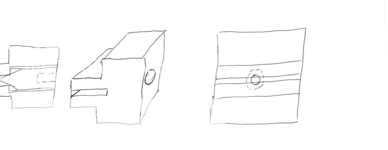
                              May I offer this highly detailed CAD drawing of a stop that utilises only the parallel sided slot you already have ?
                               

                              Basically it’s a tee shaped tenon that fits your slot in the side, the tenon has a saw cut and a hole drilled thru it then opened out and tapped.
                              A tapered grub screw is then inserted and this will force the tenon apart and so grip the sides of the  original slot.
                               
                              John S.


                              #54339
                              Spurry
                              Participant
                                @spurry
                                Thanks for the idea John.
                                 
                                That could be a short term solution, whilst I gather some courage (and tools) to machine the table.
                                 
                                My first thought would be to use an M5/M6 caphead with a turned taper, or have you deliberately used a grub screw to restrict the amount of sideways pressure that could be exerted on the casting?
                                 
                                Thanks again
                                 
                                Pete
                                 
                                 
                                #54342
                                Billy Mills
                                Participant
                                  @billymills
                                  Pete,
                                  Try number two… bolt an arm to a spare slot then install two posts ( bolt,  nut and washer into tee nut) into the mill table. Before you turn on the coolant set the posts to hit the arm at 90 degrees apart. Turn on the great flood then machine away. 
                                   
                                  If you are worried about the arm moving then use a second tee nut in the table to fix the arm.
                                   
                                  Sorry, thought that your problem was indexing at 90 degree intervals.
                                   
                                   
                                  Regards,
                                  Alan.
                                   
                                  HEATH ROBINSON HAD SHARES IN A STRING AND CANDLE FACTORY.
                                  #54362
                                  Spurry
                                  Participant
                                    @spurry
                                    Thanks Alan.
                                    That could be useful as a stop location. (The start is not usually a problem) On the job I messed up, I was cutting 1″ thick material plate to a semi circular shape. In order to prevent the groove normally caused by lingering with the cutter, I downfed the cutter by hand, locked the quill, and started winding the table all at once.
                                     
                                    At the end it was difficult to coordimate the opposite actions, especially not being able to see the table markings.
                                     
                                    I now have no excuses for making such an error again.
                                     
                                    Pete
                                    #54378
                                    Peter Gain
                                    Participant
                                      @petergain89847
                                      Hi,
                                      An allied topic. I have a rotary table that has a small collar upstand protruding from the centre hole. The hole will accept a No. 2 MT but the 5mm upstand prevents securing work directly to the table.
                                      Does anyone know how to remove this collar?
                                      The table, which I purchased second hand, may be a Vertex. The finish suggests Far Eastern, it certainly does not appear to be European/USA.
                                      All suggestions welcome.
                                      Regards,
                                      Peter Gain.
                                      #54379
                                      Keith Long
                                      Participant
                                        @keithlong89920

                                        Peter 

                                        That sounds a bit odd – it couldn’t be a 3-2MT sleeve stuck in there could it?  Can you get to the back of the hole to see if you can see any signs of such a sleeve?

                                        Keith

                                        Edited By Keith Long on 17/08/2010 14:18:54

                                        #54381
                                        chris stephens
                                        Participant
                                          @chrisstephens63393
                                          Hi Peter,
                                          If your table is anything like mine, all you have to do is hit it with an hammer, sorry that should read, all you have to do is press it firmly in your  your fifty ton hydraulic press.
                                          If you do not have such a press, try the hammer method. (with a piece of soft packing if you don’t have a sense of humour), The Morse sleeve is removable, I found this out when trying to remove a Morse fitting .
                                          chriStephens 
                                          #54382
                                          Spurry
                                          Participant
                                            @spurry
                                            Peter G
                                             
                                            My table is a Vertex, but has no central upstand. It’s so long ago that I took it apart, I cannot remember the exact construction. There is a picture of it in my gallery .
                                             
                                            I know I made an adapter with a 10mm central locator hole, the outside of which is a short length of Morse Taper. Is it possible to take a picture?  it’s much easier to see a problem than read about one.
                                             
                                            Pete
                                            #54389
                                            Peter Gain
                                            Participant
                                              @petergain89847
                                              Hi,
                                              Thanks to everyone who replied so quickly. I think that the explanation is that said “collar” is in fact a MT2 – 3 adaptor. I have the table set up for machining a small crankcase at the moment so cannot confirm. But I now know what to look for when I break down the set up.
                                              Regards
                                              Peter Gain.
                                              #54402
                                              Ramon Wilson
                                              Participant
                                                @ramonwilson3
                                                Ah Peter and would that be a certain crankcase
                                                 
                                                Is it going well?
                                                 
                                                Regards – Ramon
                                                #54405
                                                John Olsen
                                                Participant
                                                  @johnolsen79199
                                                  My experience with Morse adaptor sleeves is that they love to stay on the smaller taper, leaving you with very little to get at to knock them of!
                                                   
                                                  So while we are on rotary table ideas, I recently had occasion to bolt down the ends from my water tube boiler on the table so that I could cut the groove for the copper gasket. These are a disk of steel about 8 and a half diameter, and an inch thick, so just over the size of my 8 inch table.  *  They have three holes in them, and of course the table has four slots. Extra holes not acceptable in either the table or the boiler ends. So I cleaned up a bit of 5/16 plate that was lying around, drilled it with 7 holes, four to match the slots and use a countersunk allen screw, and three to match the stay holes on the plate.  The three scews holding down the job were tapped into the plate, the length being carefully adjusted so they don’t go right through and mark the rotary table. Did that job fine, and now I have a “sacrificial” table that I can use for any other tricky jobs, just drill and tap wherever needed for the particular project. When it gets too much of the Swiss cheese look, throw away and start again. You can get a much firmer setup like this too, no dogs trying to slip off the job. I have done the same thing on my little Unimat, most often for turning, and also on the Myford to allow boring things that are really too big.
                                                   
                                                  * for those wondering, this is not a model boiler, or if it is it is 12″ to the foot. Being built to ASME standards and inspected professionally. 
                                                   
                                                  regards
                                                  John
                                                   
                                                  #54518
                                                  Peter Gain
                                                  Participant
                                                    @petergain89847
                                                    Hi,
                                                    Thanks to those who replied re-the “collar” in the centre of my rotary table. It is just what you predicted; a 2/3 Morse adaptor that stands proud of the table. I was able to knock it out without much trouble. (My 50 ton press is out of commission). One of those little problems which are obvious once someone tells you! Another example of useful help from this forum.
                                                    Thanks,
                                                    Peter Gain.
                                                    PS to Ramon, the Nova crankcase is nearly finished.
                                                  Viewing 24 posts - 1 through 24 (of 24 total)
                                                  • Please log in to reply to this topic. Registering is free and easy using the links on the menu at the top of this page.

                                                  Advert

                                                  Latest Replies

                                                  Viewing 25 topics - 1 through 25 (of 25 total)
                                                  Viewing 25 topics - 1 through 25 (of 25 total)

                                                  View full reply list.

                                                  Advert

                                                  Newsletter Sign-up