FWIW, my view is that the higher the ratio, the more precisely angular movements can be made.
Better that an error on the handle results in a 90th of that error than a 40th!.
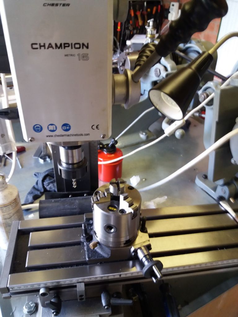
A Rotary Table that can be set on the milling machine table in either horizontal or vertical mode can be used in lieu of a Dividing Head (Especially if Division plates are available )
In horizontal mode it can be used to cut arcs, or round the ends of workpieces, as well as spacing tappings or dowel holes..
With the table vertical, it can be used to graduate / drill an external diameter, or to mill faces at an angle, and to cut splines or gears.
(My technique is to use a chuck in the lathe, on an arbor that will fit into the Rotary table, to turn the gear blank )..
In my case this involves using adaptor sleeves in the lathe, which are then removed to mount the chuck, complete with workpiece, into the Rotary Table on the mill to cut the teeth. (Again, in my case, a small Myford fitting chuck is mounted on a 2MT arbor. In the lathe a drawbar holds it in place, and in the R T, an Allen capscrew and top hat bush pull it into the taper.
If you propose to work in this way, it is worth buying a matching Tailstock, and setting it up to the same level as the R T. This provides support for the heavy loads involved in gear cutting.
I fitted the Tailstock with two dowels to locate in the T slots of the mill table. They may need to be stepped. . I bored a 2MT stub arbor to a very close fit on the Tailstock arbor. In this way the Tailstock can be adjusted to exactly the centre height of the Rotary table, and the Tailstock, being located on the mill table, aligns the Rotary table along and across the mill table.
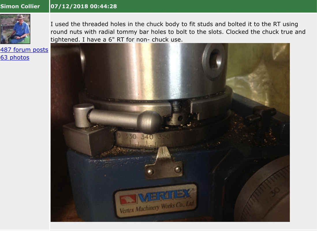
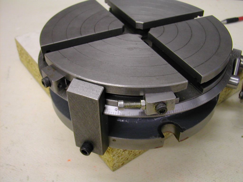
The angular spacings can be made by either using the vernier scale, or Division Plates
Do check that the Division Chart supplied with the R T and Division Plates, is accurate.. I found, the hard way, that mine contained errors and omissions.
HTH
Howard. Emojis – GRRR
Edited By Howard Lewis on 23/12/2022 01:58:35
Howard Lewis.


