Hi Derry,
At the moment I use my Super 7 with Mach 3 and a single pulse per rev sensor but since seeing the comments about EMC2 giving better threading I thought that I might give it a go so have been looking into the encoder "problem".
First, I think it's true that you can choose other numbers for steps/rev for EMC2 – in the Integrator Manual (p. 226) it has this configuration code:
loadrt encoder num_chan=1
addf encoder.update-counters base-thread
addf encoder.capture-position servo-thread
setp encoder.0.position-scale 100
net spindle-position encoder.0.position => motion.spindle-revs
net spindle-velocity encoder.0.velocity => motion.spindle-speed-in
net spindle-index-enable encoder.0.index-enable <=> motion.spindle-index-enable
net spindle-phase-a encoder.0.phase-A
net spindle-phase-b encoder.0.phase-B
net spindle-index encoder.0.phase-Z
net spindle-phase-a <= parport.0.pin-10-in
net spindle-index <= parport.0.pin-11-in
The line in red seems to configure the number of steps per rev so you can change this – and in some other forum I saw comments that one could change this, someone mentioned using 4096 steps per rev!
See http://www.linuxcnc.org/index.php/english/component/kunena/?func=view&catid=9&id=17199#17207
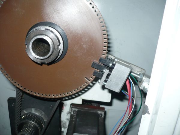
Making an encoder should not be hard if you have access to a dividing setup or could improvise something. Tony Jeffree I think gave some instructions in MEW a while back. If you could make a disc with 60 slots and monitored the slots with a photo-interrupter it should do the job, or 100 slots but you need to work to slightly finer tolerance. Photo-interrupters are dead cheap from RS Components, or even better free from a scrap printer. If you make one of the slots wider, but with its leading edge still in the right position, then if you have two opto sensors at different positions a single additional cheap IC will generate a once-per-rev index pulse. (That's assuming that EMC2 is edge triggered, if it isn't then you just need a divide-by-2 to remove the effect of the wider slot though.) Of you could make an extra hole in the disc for the second opto sensor to generate one pulse per rev; or use a small magnet on the mandrel with a Hall switch which is very cheap as well – see Tony Jeffree's articles on ML7 CNC conversion. Or, if the headstock timing pulley is steel, use one Hall sensor with an additional fixed magnet to generate one pulse per tooth; with another magnet on the mandrel and another Hall switch for the Z index pulse. I don't think that it's necessary for the Z and A pulses to have synchronous edges, but you could ask that question on the EMC forum thread linked above.
John.
Joseph Ramon.


