Rolling up a smokebox

Advert

Rolling up a smokebox

Home Forums Workshop Techniques Rolling up a smokebox

Viewing 23 posts - 1 through 23 (of 23 total)
  • Author
    Posts
  • #192006
    Baz
    Participant
      @baz89810

      Gentlemen, I want to roll up a smokebox from 2.5mm (3/32 inch) brass sheet. The outside diameter is 5.625 inches and bore 5.437 inches. What length do I need to cut the material to, is it o/d times Pi or i/d times Pi the difference in the two being .591 or is there some other formula? I only have enough material for one attempt so I cannot cut a test piece and do it by trial and error.

      Advert
      #15784
      Baz
      Participant
        @baz89810
        #192007
        JasonB
        Moderator
          @jasonb

          It's measured about 2/3rds through the thickness so about 5.5" dia x pi, I'm sure somebody will come along with the exact formula

          #192016
          Engine Builder
          Participant
            @enginebuilder

            When you roll sheet is stretches. If you cut the material to the calculated length it will be too long. I would roll it over length and then get a strip of paper cut to the circumference required and wrap it around the metal and trim to length. Silver solder the ends and re roll to true it up.

            When I rolled steel for traction engine wheels 12" dia the metal stretched 1/4" or more.

            #192022
            JasonB
            Moderator
              @jasonb

              Thats why the length of the neutral arc is what you cut the metal to, the inside compresses and the outside stretches.

              Using my approx figures above the piece will be 0.190" shorter than the outside circumferance

              #192031
              Anonymous

                When I made the rims for my traction engine front wheels I calculated as follows. The OD of the completed wheel is 15", and the thickness of the steel tyres is ¼", so subtract ½" to get 14½", the OD of the rim itself. The rim material is 3/16" so subtract another 3/16" to get the diameter of the neutral line, assuming that the neutral line is at 50% of the material thickness. The neutral line diameter is 14.3125" giving a circumference of 44.964". That's the length I cut the metal to; well an approximation as I used a tape measure to check the length. Once rolled and welded the rim was pretty much spot on the right diameter. The T-ring, which was welded from 4 laser cut arcs, is a tight push fit:

                front wheel rim.jpg

                Andrew

                #192033
                Speedy Builder5
                Participant
                  @speedybuilder5

                  The problem you will find is that the first part of the rolled sheet will not be the right curve, also the last bit – i.e. the distance between the pinch rollers and the form (3rd) roller. So, what to do. How are you making the seam – Smokebox, are you just brazing the joint, or butt strap and rivets. If just brazing/silver solder, you can roughly bend the joint edges to shape, braze, clean the joint and then back onto the rolls to get the shape perfect (assuming you can slip the smokebox back onto the rolls). Other wise you have to finish the smokebox by forming over a large pipe. Steel lamposts are a good source of round tube – bit difficult to get hold of perhaps. I suppose a bit of 4" plastic tube filled with concrete may be solid enough.
                  Good luck
                  BobH

                  #192041
                  Anonymous
                    Posted by Speedy Builder5 on 01/06/2015 21:06:07:

                    The problem you will find is that the first part of the rolled sheet will not be the right curve, also the last bit – i.e. the distance between the pinch rollers and the form (3rd) roller. So, what to do.

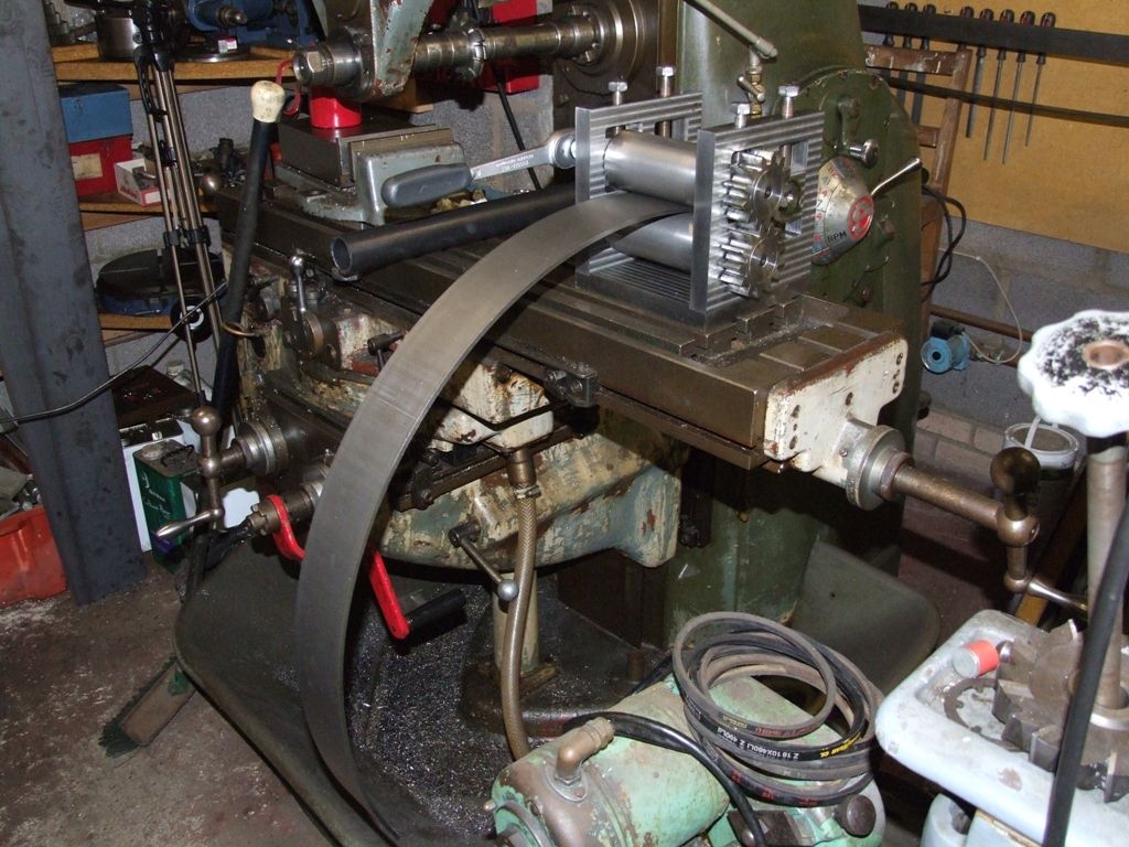
                    True for pyramid rolls, but not so for initial pinch rolls if you reverse the direction of the material at each pass. For rolling my wheel rims I made a set of initial pinch rolls:

                    bending_rolls.jpg

                    Andrew

                    #192049
                    Paul Lousick
                    Participant
                      @paullousick59116

                      The outside of the plate stretches more than the inside compresses when you bent the plate. Jason's figure of 2/3 is a good approximation for the position of the neutral axis. Good enough for what we do to roll wheels, etc. Check diameter after rolling. Trim a little if too big or weld gap if too small. Then re-roll after welding to smooth out the flats on the 2 ends.  For a more accurate formula refer to:

                      http://www.thefabricator.com/article/bending/the-basics-of-applying-bend-functions

                      Paul.

                      Edited By Paul Lousick on 02/06/2015 01:50:13

                      #192082
                      Anonymous
                        Posted by Paul Lousick on 02/06/2015 01:45:11:

                        The outside of the plate stretches more than the inside compresses when you bent the plate. Jason's figure of 2/3 is a good approximation for the position of the neutral axis. Good enough for what we do to roll wheels, etc. Check diameter after rolling. Trim a little if too big or weld gap if too small. Then re-roll after welding to smooth out the flats on the 2 ends.

                        I think it is rather more complex than that. Out of curiosity I measured the OD of my wheel rim in four places with a micrometer. These are the values I got (nominal size 14.5" ):

                        14.490" 14.480" 14. 491" 14.494"

                        I assumed that the neutral line was 50% of material thickness with a sequence of cut, roll and weld, ie, no adjustments. I used initial pinch rolls to bend the rims, so there were no flats that needed to be removed or re-rolled.

                        Intuitively the location of the neutral line will depend upon the relative compressive and tensile forces. Many formulae are quoted for bend allowances. The key here is that the bend radius is often equal to, or not much more than, the material thickness. Again intuitively for a small bend radius the compressive forces on the inside will be higher than the tensile forces on the outside, the result being that the neutral line moves towards the OD.

                        However, for rolling wheel rims, and smokeboxes, the bend radius is much larger than the material thickness, so it is likely that the compressive and tensile forces are nearly equal and hence the neutral line will be around 50%.

                        Andrew

                        Edited By Andrew Johnston on 02/06/2015 12:05:30

                        #192083
                        JasonB
                        Moderator
                          @jasonb

                          I did find a formula on the net last night that took into account the bend radius so as Andrew says the neutral axis will move depending on the bend radius and I suppose the material may also have an effect.

                          Another option to avoid an egg shaped ring due to the ends not rolling well is to cut two strips say 60% of the required length each and then cut a bit off each end so you end up with two half circles that can be joined.

                          J

                          #192103
                          Paul Lousick
                          Participant
                            @paullousick59116

                            Andrew,

                            If you need a more accurate calculation to find the neutral axis for bending plate check the web site which I listed earlier.

                            Paul.

                            #192105
                            JasonB
                            Moderator
                              @jasonb

                              I only have a basic version of Alibre without the sheet metal function, does anyone with a sheet metal function to their CAD software know if that will give the length to cut the metal for a given thickness and radius?

                              J

                              #192137
                              Anonymous

                                I have the Expert version of Alibre, including the sheet metal function. One can specify the metal thickness, minimum bend radius and the K value, default value is 0.330. Once a part is designed by adding bends and folds then it is a simple button push to get a flat pattern to cut to, taking into account the metal used in the bends. I've used the facility quite a lot and it does seem to work. However, the facility does have some limitations and ironically, given the original post, one thing it does seem to fall down on is large radius bends. It fell over completely when I tried to model the brake band for my traction engines.

                                Andrew

                                #192142
                                JasonB
                                Moderator
                                  @jasonb

                                  Thanks Andrew.

                                  #192149
                                  Neil Wyatt
                                  Moderator
                                    @neilwyatt

                                    I've never done this, but my instinct would be to cut slightly over length and file the ends to get it spot on. Hand filed won't be an issue if you are brazing the joint.

                                    Neil

                                    #192237
                                    Muzzer
                                    Participant
                                      @muzzer
                                      Posted by Paul Lousick on 02/06/2015 01:45:11:

                                      …..re-roll after welding to smooth out the flats on the 2 ends. For a more accurate formula refer to:

                                      http://www.thefabricator.com/article/bending/the-basics-of-applying-bend-functions

                                      Paul.

                                      Edited By Paul Lousick on 02/06/2015 01:50:13

                                      Paul – if you look on the same site you linked to, you'll see an explanation of why initial pinch rolls don't generate a flat at each end of the strip.Typical for Andrew to have sussed this out before making his rolls…

                                      Murray

                                      #196152
                                      Baz
                                      Participant
                                        @baz89810

                                        Gentlemen, sorry to have been so long in replying, I can however report some success. I have now rolled up two pieces of brass using a set of George Thomas bending rolls and am very pleased with the result. I finally settled on an overall length of 17.395 inches which is 20 thou longer than pi times the mid diameter. Thank you all for your help

                                        Baz

                                        #196206
                                        Ajohnw
                                        Participant
                                          @ajohnw51620

                                          There is an interesting set of rolls shown in this video. He had the design published in Model Engineer around 20 years ago. The cranks at each end are phased at 90 degrees.

                                          **LINK**

                                          Odd thing. I have seen tin smiths rolling with a similar design but with gears. It isn't just thin tin plate that they were rolling either. Gears rather than cranks but the same simple arrangement. I would make the handle longer as it can be hard work.

                                          Pinch rolls as per G Thomas gain a little if the material is reversed but having seen this design I just have wonder if it's worth the effort. Or the other type as well.

                                          John

                                          #196222
                                          John Shepherd
                                          Participant
                                            @johnshepherd38883

                                            The rolls in the above link are interesting but so was the adaptation of a sander to vibrate the cement! The steel ring made with the rolls is for part of a furnace that is filled with refractory cement and a bar was bolted to a hand held sander and used to make sure the cement was evenly distributed. I looked at the video just to see the rolls but found my self watching the whole thing.

                                            John

                                            #196314
                                            Engine Builder
                                            Participant
                                              @enginebuilder

                                              Considering most sets of rolls would only get occasional use the ones shown in the video would be quick and easy to make. Not in the same class as the George Thomas ones but certainly up to the job.

                                              I also like the power hacksaw shown in the video.

                                              #196324
                                              Ajohnw
                                              Participant
                                                @ajohnw51620

                                                I have an interest in casting come up – parts for a telescope that I can't turn up on my lathe. It will save a lot of waste too as it will be mostly a hole. He's the best source of info I have come across and watching him work generally I get the impression he knows what he is doing all round.

                                                He was also cutting thick steel with a circular hand saw commercially made for just doing that. Might be in the same video series. Not sure.

                                                John

                                                Edited By John W1 on 09/07/2015 23:39:42

                                                #196325
                                                julian atkins
                                                Participant
                                                  @julianatkins58923

                                                  here's one 'i did earlier'

                                                  dsc00762.jpg

                                                  dsc00763.jpg

                                                  dsc00766.jpg

                                                  dsc00769.jpg

                                                  the rollers were made out of old loco axles and an old buffer beam, and cope quite ok with 1/16" steel.

                                                  cheers,

                                                  julian

                                                Viewing 23 posts - 1 through 23 (of 23 total)
                                                • Please log in to reply to this topic. Registering is free and easy using the links on the menu at the top of this page.

                                                Advert

                                                Latest Replies

                                                Home Forums Workshop Techniques Topics

                                                Viewing 25 topics - 1 through 25 (of 25 total)
                                                Viewing 25 topics - 1 through 25 (of 25 total)

                                                View full reply list.

                                                Advert

                                                Newsletter Sign-up