Rod’s Hoglet

Advert

Rod’s Hoglet

Viewing 25 posts - 26 through 50 (of 103 total)
  • Author
    Posts
  • #614450
    Roderick Jenkins
    Participant
      @roderickjenkins93242

      Richard,

      Good thought. Not much room for a 6" rule but a craft knife blade would probably work nicely.

      Cheers,

      Rod

      Advert
      #614770
      GrahamS
      Participant
        @grahams

        Hi Rod,

        Great work on the camshaft.

        Any chance of more pictures of your good one please , especially end on from the 'long end' to match the drawing and similar views to understand the cam orientation compared to the drawing.

        I have pressed ahead with the cylinders , about to start cutting the fins.

        Thanks

        Graham

        #615162
        Roderick Jenkins
        Participant
          @roderickjenkins93242

          Graham,

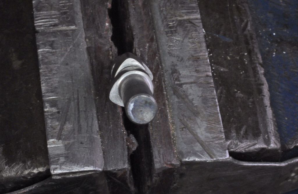
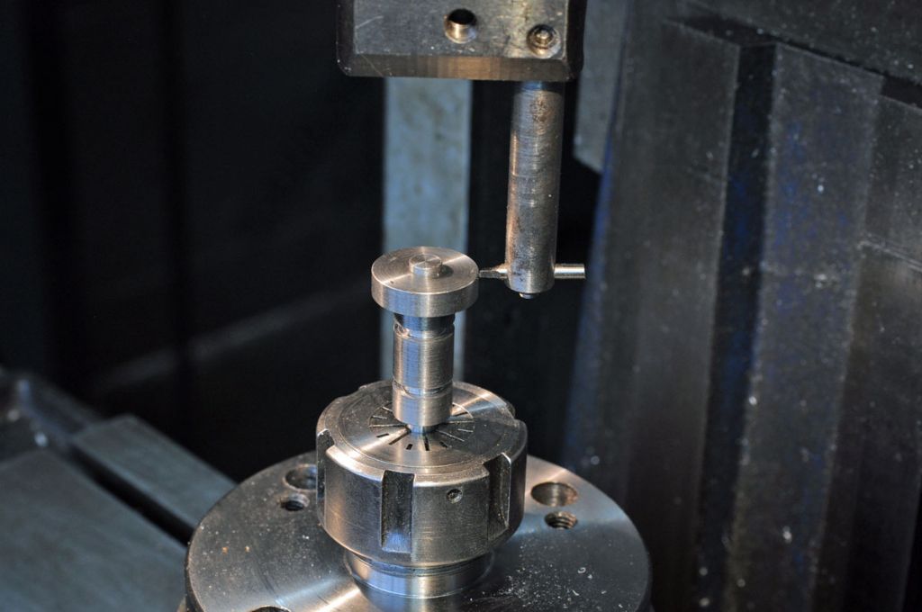
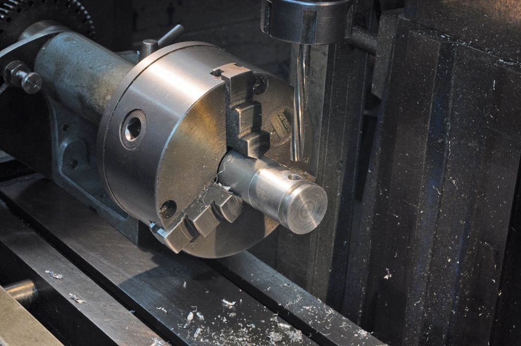
          Here's a pic from the long end. I can't guarantee that it is correct but at least it looks like Jason's. If I were to use the Cox method again I would make a foreshortened version in aluminium and start with the middle cam first to make sure that I understand the correct way to rotate the blank between cams.

          h53.jpg

          Incidentally, I made a setting ring 0.8" diam for the cutting radius

          h54.jpg

          Hope this helps,

          Rod

          #615274
          ianj
          Participant
            @ians

            Rod.

            I started building my engine after seeing your first post. My cam looks very much like yours, so hopefully we are both correct! My progress upto now; Have you and Graham given any thought to ignition and carb.

            Ian

            p9280800.jpg

            p9280795.jpg

            #615387
            Roderick Jenkins
            Participant
              @roderickjenkins93242

              Ian,

              Looking good.

              Ignition wise, I've plumped for the RCEXL unit that Andew Whale used **LINK**

              For a carb I'm going to try the one I made according to the drawings for my Matador which also worked very nicely on my Wyvern. If that works I'll make one with the same internals to better suite the Hoglet.

              Rod

              Edited By Roderick Jenkins on 29/09/2022 00:59:44

              #615418
              GrahamS
              Participant
                @grahams

                Ian,

                Looks excellent, well done and in quick time as well ! I thought I was progressing quickly , having started in late Feb, but both you and Rod are steaming ahead.

                I feel a right numpty over this, but I just cant get my head around the camshaft. The drawing dimensions the angles looking from the cam gear end with the middle cam being 101 degrees clockwise on from the cam closest to the cam gear , and the third one being 113 degrees further on from the second. Fine.

                The obvious way to machine it using the Cox method is to hold the long cam gear end in a collet vertically as shown by Jason and Andrew Whale.

                What I dont understand is in his video Andrew, working down the cams uses 0, 101, 113 as the lobe angles which surely is back to front ? Using the Cox method, starting at the highest cam ( the one at the crankcase end ) the separation angles should be the reverse of the drawing i.e. 0 ,113,101 ? Now Andrews engine clearly runs so I find it hard to discount his choice, it just seems to be at odds with the drawing.

                Another thought is it might just run made either way !

                Apologies for warbling on, but I have been mulling this over for months now, and I can see the camshaft being the last piece to make ! Can I ask you Ian, did you use the Cox method to make the camshaft , and what angles you choose working down the stack of cams?

                Thanks

                #615448
                ianj
                Participant
                  @ians

                  Hi Graham.

                  Yes I used the Cox method. But like you I thought Andrews method was back to front. What I did was to prepare the cam blank and drill it 1/4" then loctite it onto 1/4" bar long enough to hold it in the collet chuck (so in effect you are holding it by the short end) Then I machined it as in Andrews video and when done re positioned the 1/4" bar so the long end was on top. ( I may have turned the machined cam around as well) But it ended up looking like the end view drawing. Must be honest it turned my brain to mush, it took two attempts to hopefully get it correct. Just thinking about it again and looking at my trial run one I made out of Ali, you could just make the short end longer to hold in the collet machine the cams as Andrews video and then cut the collet end to length (becomes the short end. ) I think I did it my way because to keep the total length as short as possible. Also looking at my trial one there was no need to turn the cam around.

                  Hope this helps.

                  Ian

                  Edited By ian j on 29/09/2022 14:05:15

                  #615466
                  JasonB
                  Moderator
                    @jasonb

                    The angle order really comes down to what end of the cam you have pointing upwards.

                    If you have the gear end up then it will be 0 for the outer lobe, 101 for the middle wide lobe and then another 113 for the inner lobe as you work your way down. So 0 101, 214

                    If you have the frame side up then it is 0 for the inner lobe, 113 for the middle and then another 101 for the outer. So 0 113, 214

                    If you make those your three starting points and cut equal amounts from each of those start points you will get the cam right

                    So assuming gear end up make your first cut with the boring head starting at 0 degrees and rotate round to 239deg (think that is what it worked out at) to cut the outer cam

                    Then the mid cam starting at 101deg and going round to 340deg (101=248)

                    Then inner cam starting at 214deg and ending at 193deg ((214 + 239) – 360))

                    Edited By JasonB on 29/09/2022 16:50:41

                    #615467
                    GrahamS
                    Participant
                      @grahams

                      Thanks Ian,

                      Its a great relief to hear you think he is wrong way round as well ! I was struggling to get past the fact his runs, but on the face of it the cam is reversed.

                      In my correspondence with Rod about this matter, to try and relate the drawing to photos we referred to the middle cam in the drawing being at 12 o 'clock, the cam gear end one at 8 o' clock and the crankcase end one at 4 o'clock. I have a suspicion if reversed and viewed from the other end 8 and 4 are not that different ( 12 degrees different ) and if compensated by valve setting , ignition timing etc it might just run like that. Who knows ? I bet someone has done it !

                      I do like your idea of trimming the bar to length after machining the cams, so you can machine while holding down from the 'short' end so it is oriented like the drawing. If I have the headroom in the mill I will probably do that.

                      Thanks again.

                      Graham

                      #615472
                      GrahamS
                      Participant
                        @grahams

                        Thanks for the added detail Jason, that makes complete sense and helps enormously.

                        I will be making this after finishing the cylinders.

                        Well maybe not quite. I have decided to get my 30 year old Sweet Pea in boiler certificate again. I use it occasionally on a length of track in my garden, but now having retired I want to visit some local tracks again. It used to be in certificate, but when my kids grew up and left home it just sort of got forgotten about , and only run once or twice a year if that. I have done a hydraulic test myself pending the boiler inspector doing same. Lots of maintenance work to get it back up to scratch !

                        Edited By Graham Sherwood 1 on 29/09/2022 17:01:50

                        #616568
                        Roderick Jenkins
                        Participant
                          @roderickjenkins93242

                          My view of the Hoglet is that it is largely a noise maker. For just getting the engine to run then the cam timings are not at all critical – the article refers to some quite radical changes to get a more Harley like burble. If the cam angles are reversed then it should still be fine, as Andrew may have demonstrated smiley

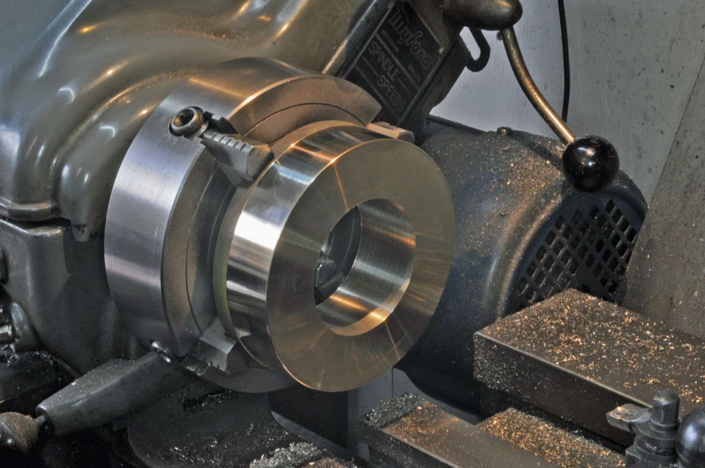
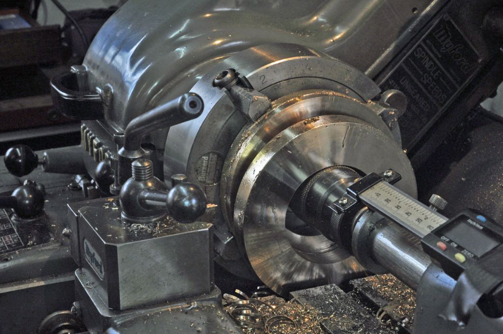
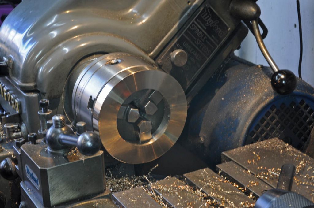
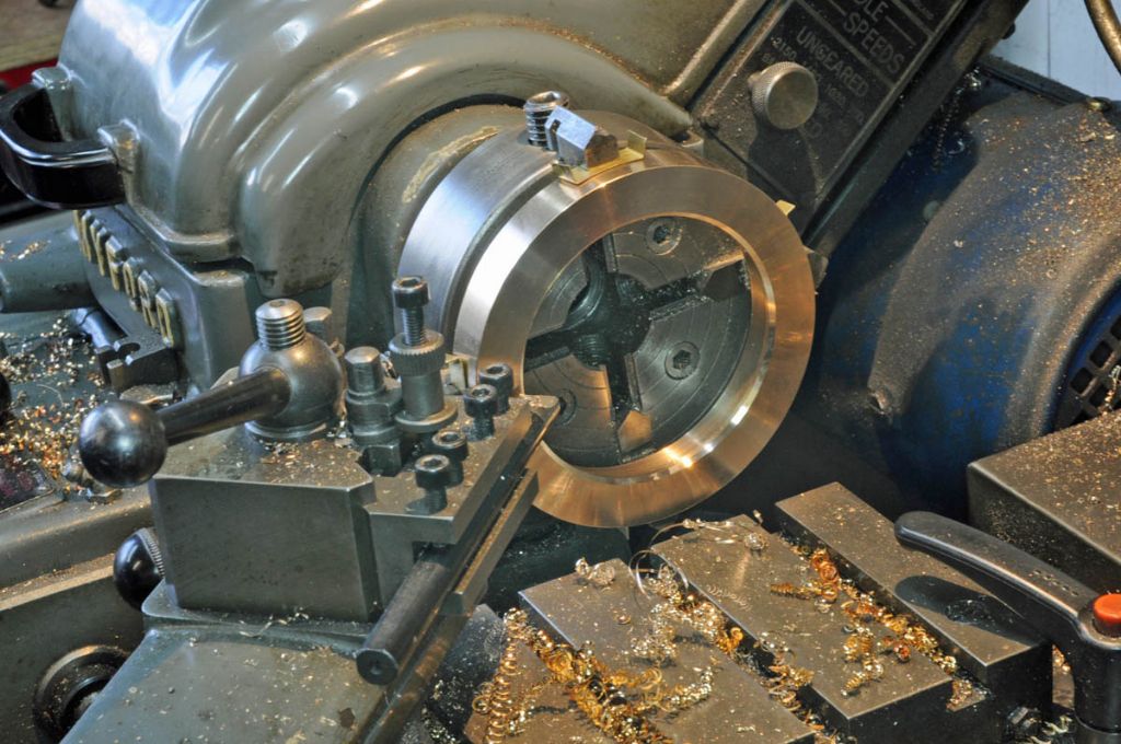
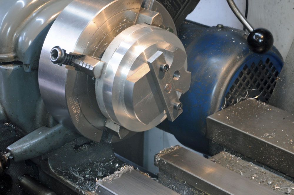
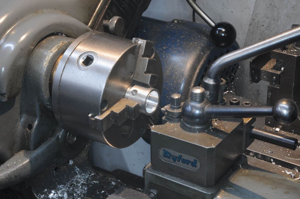
                          Flywheels. I opted for the expensive bling factor with a length of bronze pipe. Cleaned up inside and out in the 4 jaw. Cuts very nicely with a CCGT 0.4 tip

                          h55.jpg

                          Tough stuff though, parting in 2 was a struggle. My carbide insert parting blades wouldn't touch it but the HSS blade, freshly sharpened it worked OK, albeit with a lot of screeching and complaining

                          h56.jpg

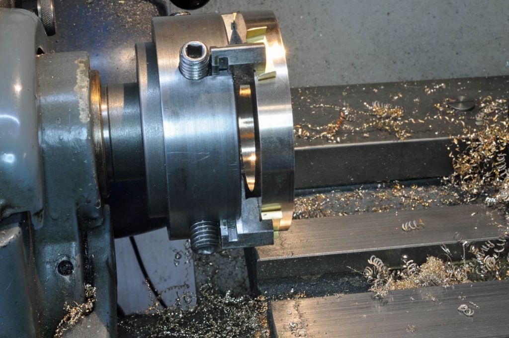
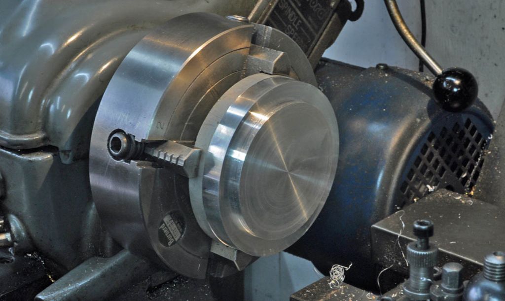
                          Held in the 3 jaw by the inner circumference for final thicknessing and O.D.

                          h57.jpg

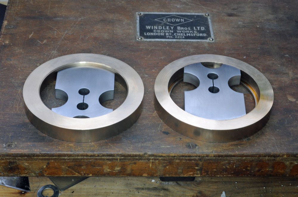
                          Then transferred to my smaller 4 jaw so that I could bring the inner measurement to size without the jaw interfering with the through cut

                          h58.jpg

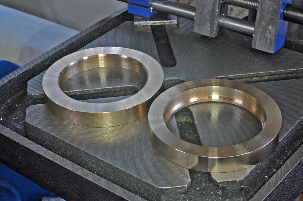
                          Then the chamfer

                          h59.jpg

                          Shiny!

                          h60.jpg

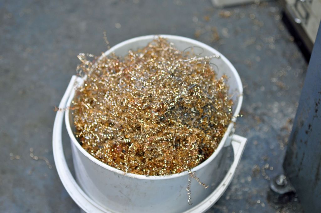
                          All that expensive swarf crying

                          h62.jpg

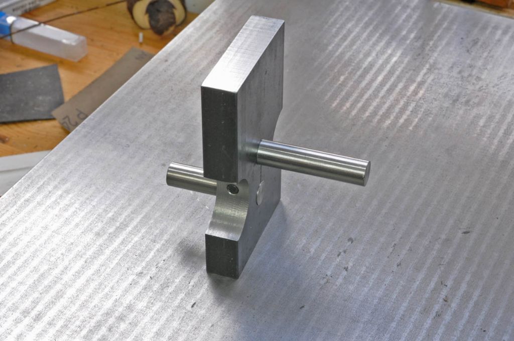
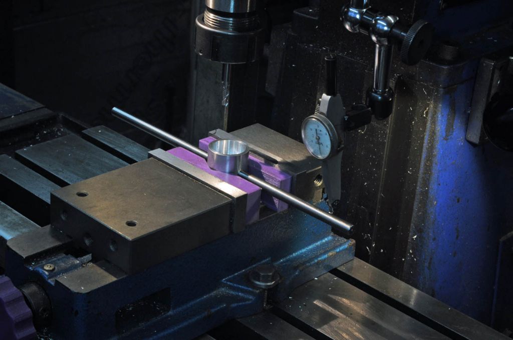
                          I was struggling to get accurate i.d. by measurement with a caliper gauge – my telescope gauges are not large enough. The crank webs need to be 3 thou over size for the shrink fit. I turned an ally spigot to fit each crank ring that I was more comfortable measuring to get an accurate figure, there is a couple of thou difference between the 2 rings

                          h63.jpg

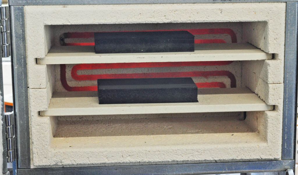
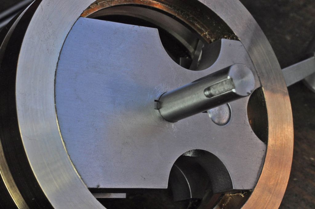
                          I've been giving some more considered thought to the issue of grabbing the crank shaft and pin in the crank web. My first thought was to minimise distortion by stress relieving the 2" x1/2" bar that I will use so I heated the blanks up to 550C in my little furnace and let them soak for an hour before allowing them to cool in the furnace.

                          h62.jpg

                          The next idea was that working on the principle that it is easier to make a shaft to fit a hole than vice versa I would ream the hole to 23/64" rather than 3/8" and turn down the end of the pin for a good, tight fit. The disadvantage of this method is that the crankshaft/con rod assembly will have to be pre-assembled and the crankcase built around it

                          h64.jpg

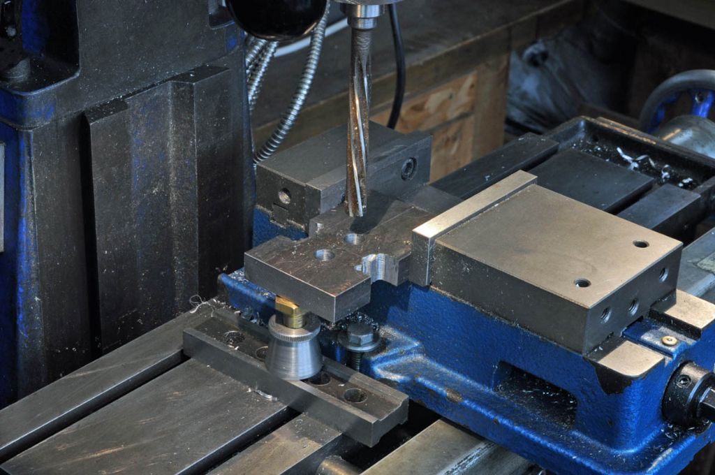
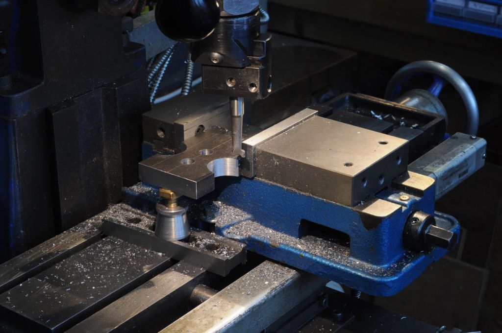
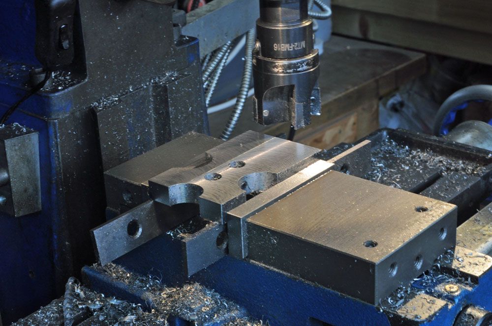
                          The weight relieving crescents were roughed out by chain drilling before finishing with the boring head

                          h65.jpg

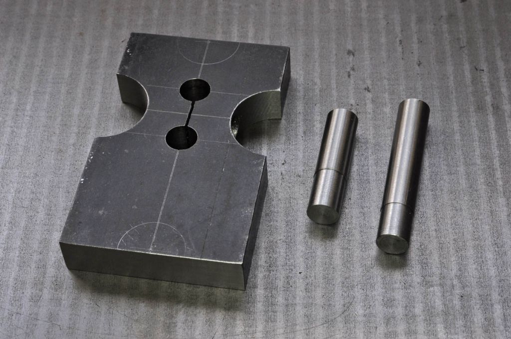
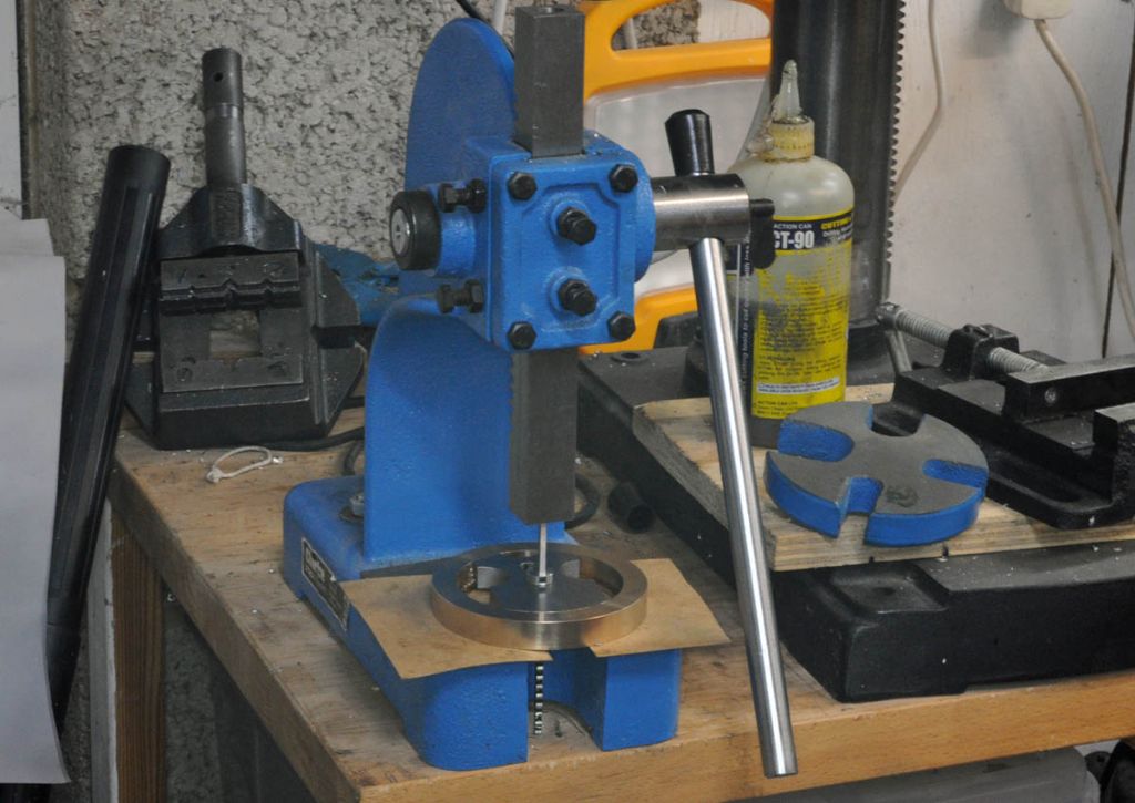
                          Quite a bit of trial and error ensued. To cut a long story short the the reamer (of unknown provenance and tolerance) is nominally 0.359" diameter. To get a pin to grip in the hole using an M5 screw to close up the holes the pins needed to be a tightish "tap home with a hammer" fit 0.362" diameter and be within 0.0002" the same diameter otherwise one would tighten and the other wouldn't. That entailed quite a bit of work with a dead smooth file

                          h66.jpg

                          Both of these pins held securely enough such that if I grip them tightly with the fibre jaws in the vice the pins will turn in the vice rather than in the web

                          h67.jpg

                          So I guess that sort of works and will have to be repeated for the other web. Whether that is better than using Loctite I'm not sure. However, the experience leads me to wonder whether an undersize 3/8" reamer might do the job. Not easy to source for a reasonable sum but a 9.5mm H7 reamer is nominally 1 thou under 0.375" and ARC sell them for a pension friendly(ish) sum. Order placed…
                          Watch this space for the next exciting installment,

                          Rod

                          #616840
                          GrahamS
                          Participant
                            @grahams

                            Looking good Rod,

                            After a lot of faf with that slot , I opted to pin it all together , followed by Loctite. Whatever works …..

                            #620679
                            Roderick Jenkins
                            Participant
                              @roderickjenkins93242

                              Well, I got the 9.5 mm reamer and a 3/8" ground and hardened dowel pin to act as the crank pin. After a lot of trial and error and worry the best I can do is to use the 9.5mm reamer followed by a nice new 3/8" H7 reamer. After tightening the screw the crank pin is very firm but the crankshaft pins less so. Does this matter? As this motor doesn't drive anything the only loads on the crankshaft are starting torque and the drive to the cam shaft (I think). If it does shift it will only be the timing that is upset. I'll probably Loctite everything anyway.

                              The webs were reduced to final thickness:

                              h68.jpg

                              The turned to final diameter. Don't let anybody tell you that you can't use a CCGT tip on an interrupted cut.

                              h69.jpg

                              I've chickened out of the shrink fit option, the webs are push fits and will be Loctited

                              h70.jpg

                              Rod

                              #620685
                              JasonB
                              Moderator
                                @jasonb

                                Looking good Rod

                                I did extend the slot in my webs beyond the other side of the crankshaft hole to allow things to close up a bit more under the load from the screw. Just thinking about it now it would be possible to add a second screw if the cutouts were extended which should pull things up even tighter.

                                hog crank web.jpg

                                Another option if you do get the shaft slipping would be to add a narrow keyway so a key could be used in that and engage in the slot with a bit of clearance so it does nor prevent the slot closing up,

                                #630099
                                Roderick Jenkins
                                Participant
                                  @roderickjenkins93242

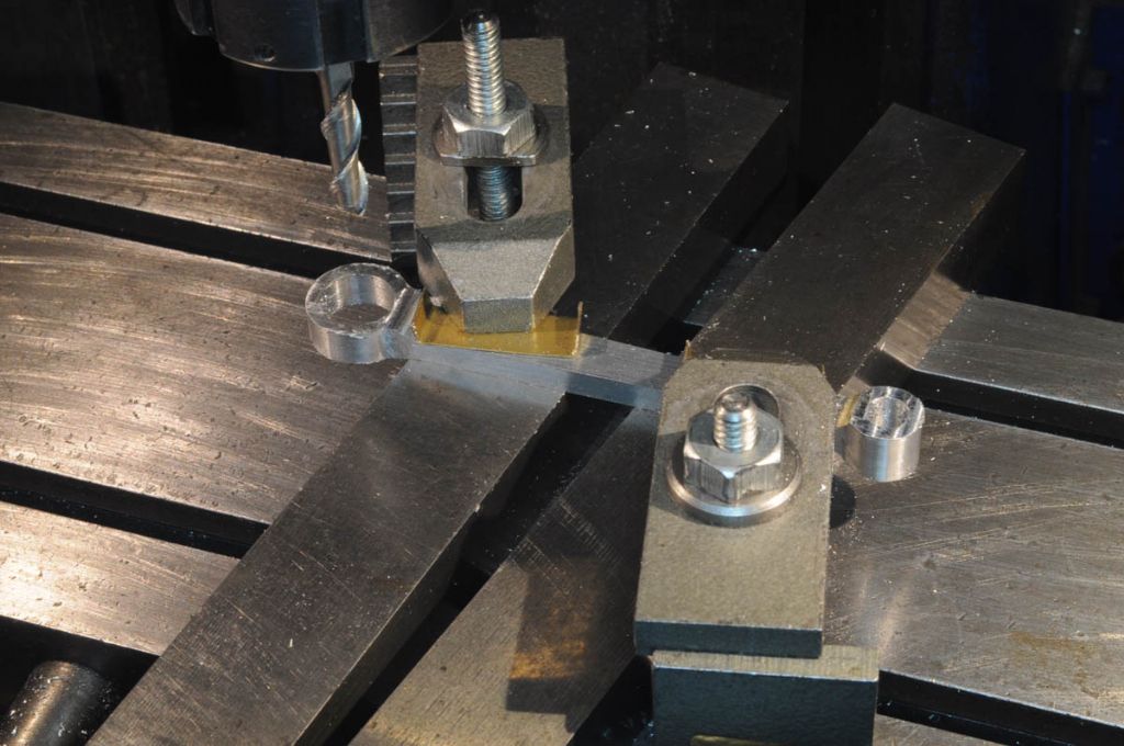
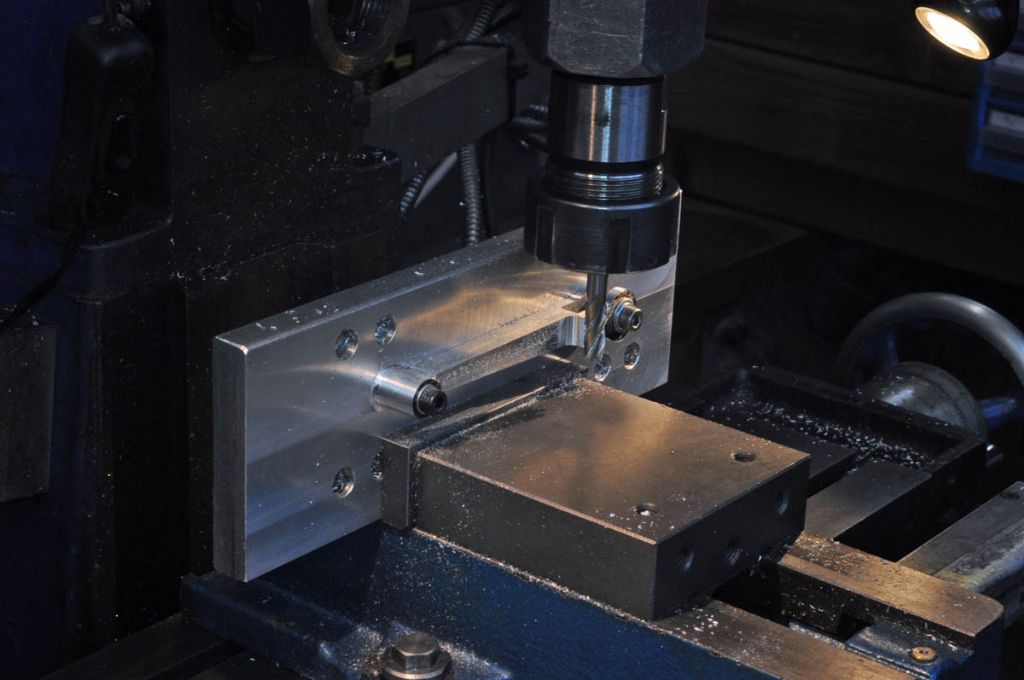
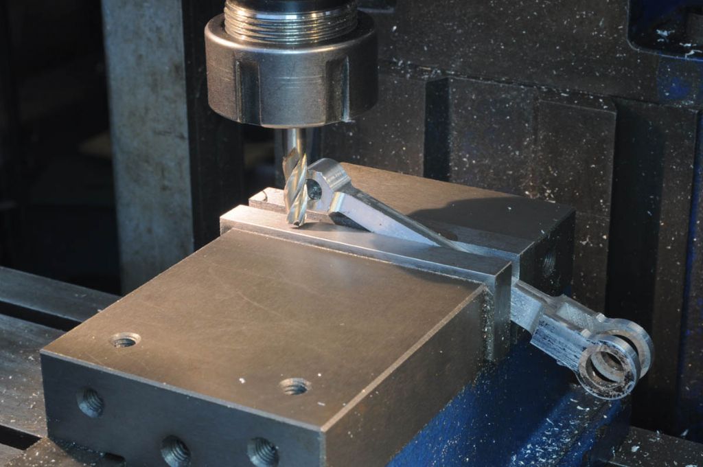
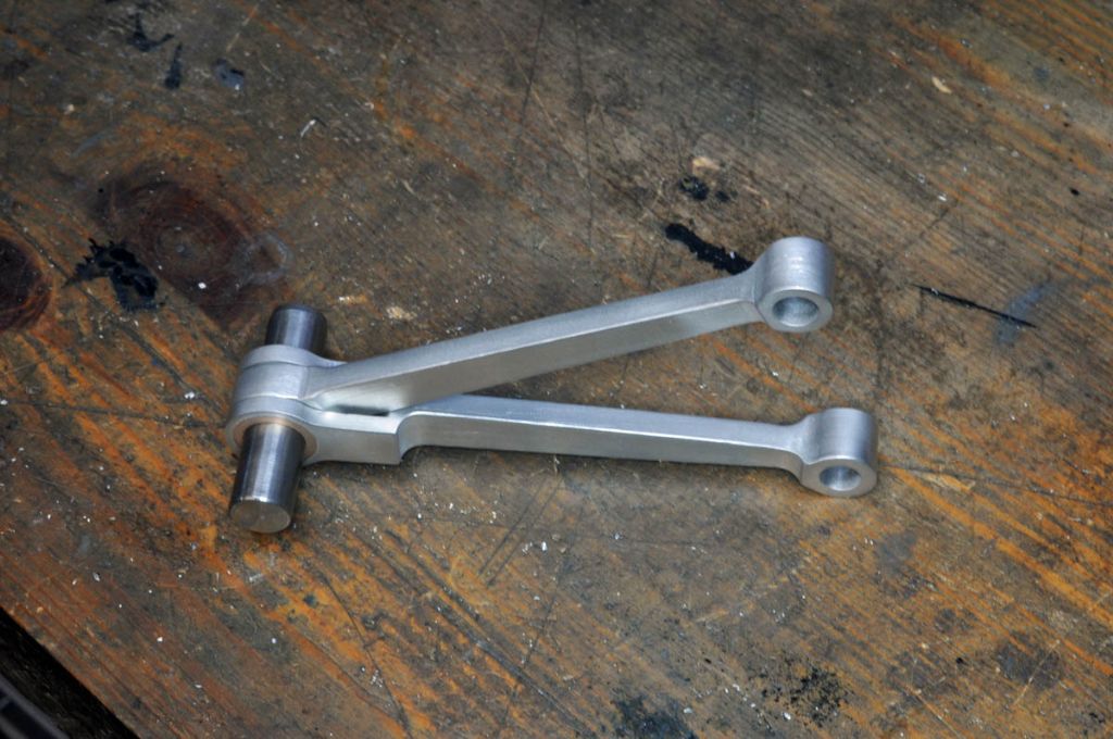
                                  It's been a while. Hoglet and I fell out so I thought it would be better if we spent some time apart. We're communicating again now (all my fault). I had spent some time debating whether to use CNC or manual methods for the con rods. I'd assumed they were much the same so the same CAD drawing would do for both. For some reason I was completely blind to the differences in the plans. Made one con rod and had to rectify some issues with the CNC mill.

                                  The blank was drilled and reamed on the manual mill for the big and little end pins, then profiled on the CNC

                                  h72.jpg

                                  h73.jpg

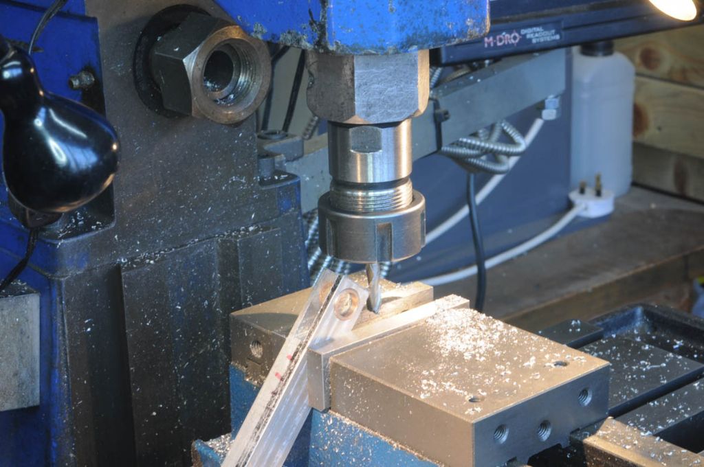
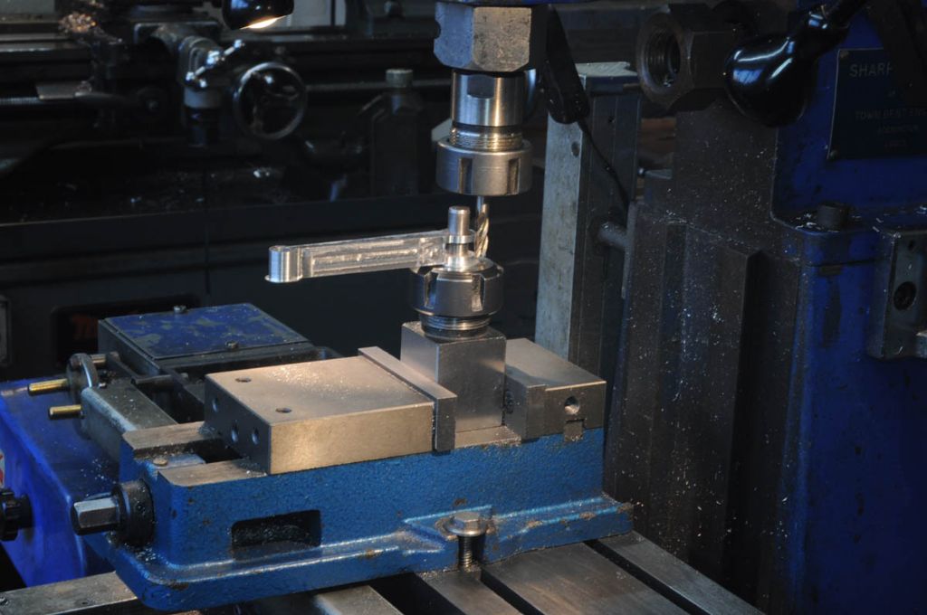
                                  Moved to the manual mill to thin the shaft

                                  h74.jpg

                                  and bring the end to the right thickness

                                  h75.jpg

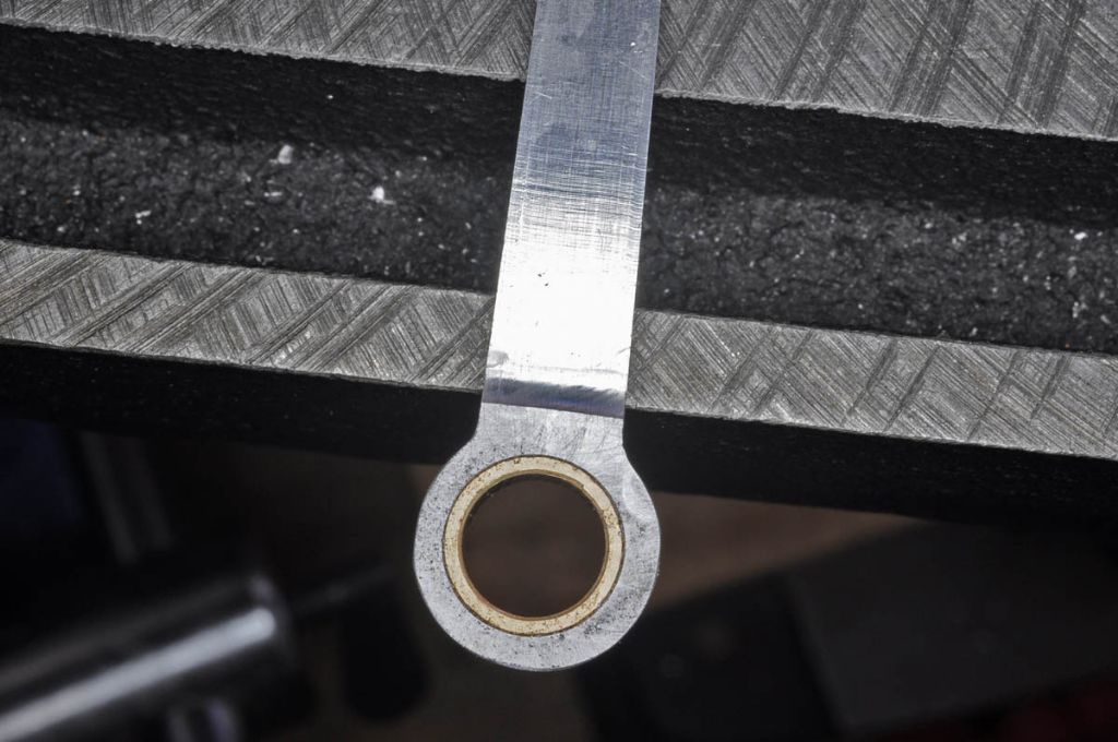
                                  I was not particularly happy with the way that plans use glacier type bearings so decided on some bearing bronze for the big end. Note the asymmetry in the bulge caused by a backlash issue on the CNC Y axis.

                                  h76.jpg

                                  It turn out (obvious really!) that the forked con rod needs relief on one side to allow free movement of the other rod in the narrow V between the cylinders and some more meat at that end to allow for it..

                                  h77.jpg

                                  Profiled manually

                                  h78.jpg

                                  h79.jpg

                                  Little end thinned to 1/4"

                                  h80.jpg

                                  After a little bit of titivating with files and scotchbrite

                                  h81.jpg

                                  Rod

                                  #630111
                                  JasonB
                                  Moderator
                                    @jasonb

                                    Nice Rods Rod

                                    I thought you might have done the thinning of the shaft on the CNC or does it only do 2D?

                                    #630325
                                    Roderick Jenkins
                                    Participant
                                      @roderickjenkins93242
                                      Posted by JasonB on 11/11/2022 18:47:35:

                                      Looking good Rod

                                      Another option if you do get the shaft slipping would be to add a narrow keyway so a key could be used in that and engage in the slot with a bit of clearance so it does nor prevent the slot closing up,

                                      Thanks Jason. I think that's the way forward. I'm using a hardened dowel pin for the crank pin so not an option there but fortunately the crank pin is gripped quite well. It is the other 2 that can be less firm and they will be un-hardened silver steel.

                                      The CNC mill is fully 3D with Fusion 360 but, illogically, it seems less trouble to use the manual mill for fairly simple shapes.

                                      Cheers,

                                      Rod

                                      #630544
                                      GrahamS
                                      Participant
                                        @grahams

                                        Have you sussed the design direction of rotation yet Rod?

                                        My gut feel is its clockwise viewed from the cam side, but as usual with this design, nothing obvious in the plans.

                                        Similarly I think the right cylinder when viewed from the cam side is what the Harley guys call the front or number 1 cylinder but not 100% sure.

                                        Nice finish on your rods. I intend to go back through the engine when finished and spend some time getting a better finish on parts, to date I have just left them as is after machining.

                                        Cheers

                                        Graham

                                        #630549
                                        JasonB
                                        Moderator
                                          @jasonb

                                          Yes clockwise from the cam side, watch Randall's video of his engine you can see the direction the kick start is turning the crank, cam is going anticlockwise so crank must be clockwise.

                                          #630619
                                          GrahamS
                                          Participant
                                            @grahams

                                            Cheers Jason !

                                            #631293
                                            Roderick Jenkins
                                            Participant
                                              @roderickjenkins93242

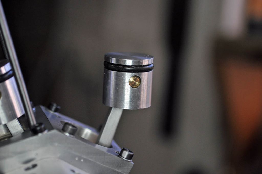
                                              Pistons are straightforward. Turned on the lathe then transferred in the chuck to the mill for drilling and reaming the hole for the gudgeon pin

                                              h84.jpg

                                              Then back to the lathe for hollowing out

                                              h85.jpg

                                              then back again to the mill to cut the relief for the little end of the con rod

                                              h86.jpg

                                              As per Jason's suggestion, the crank shafts will be keyed

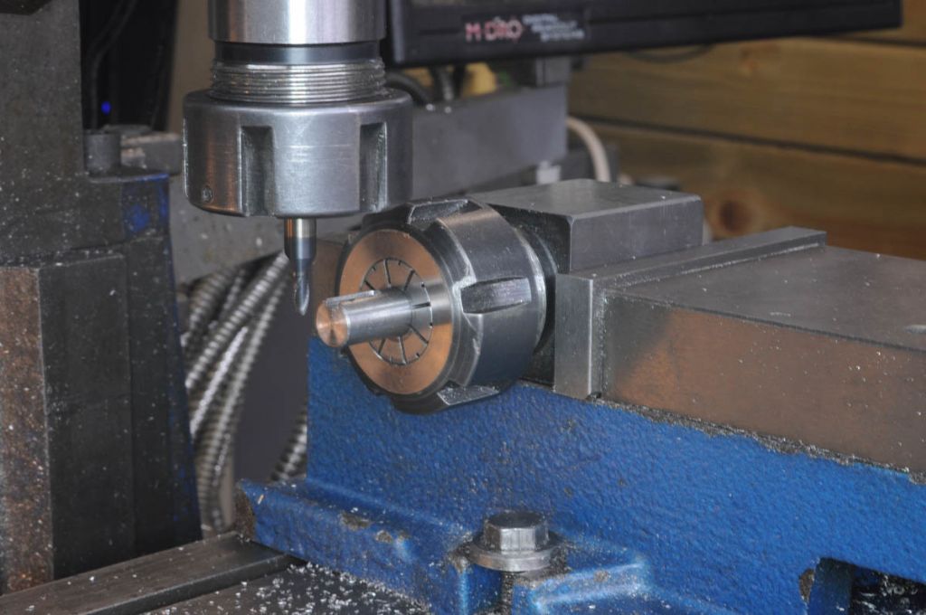
                                              h88.jpg

                                              3mm slot drill

                                              h89.jpg

                                              That seems to work

                                              h90.jpg

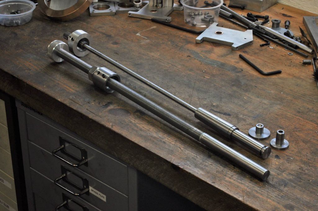
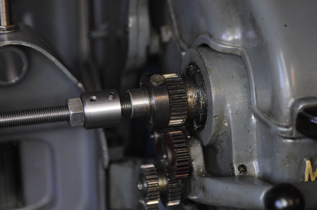
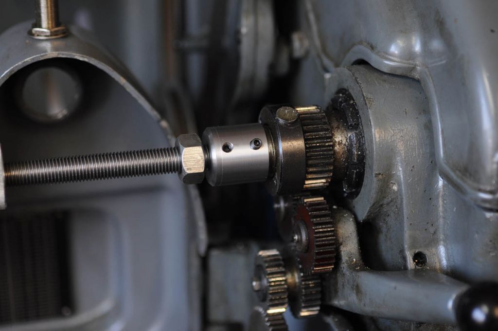
                                              The cylinder studs are 4" long and I need 8 of them so a bit of mass production called for. My original lathe backstop was designed for holding thin parts square in the chuck. The depth is adjusted by a 40tpi thread in the Morse Taper. It won't go anywhere near accommodating a 4" stud. An hour's work made a new backstop with some 1/2" BSF studding which will take longer lengths.

                                              h93.jpg

                                              h94.jpg

                                              h95.jpg

                                              h91.jpg

                                              The O rings are the same as I used to great success in my Farm Boy – rather larger cross section than specified but they are what I've got

                                              h92.jpg

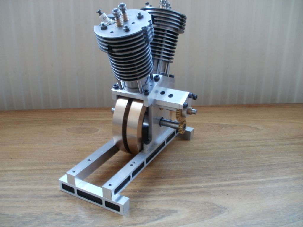
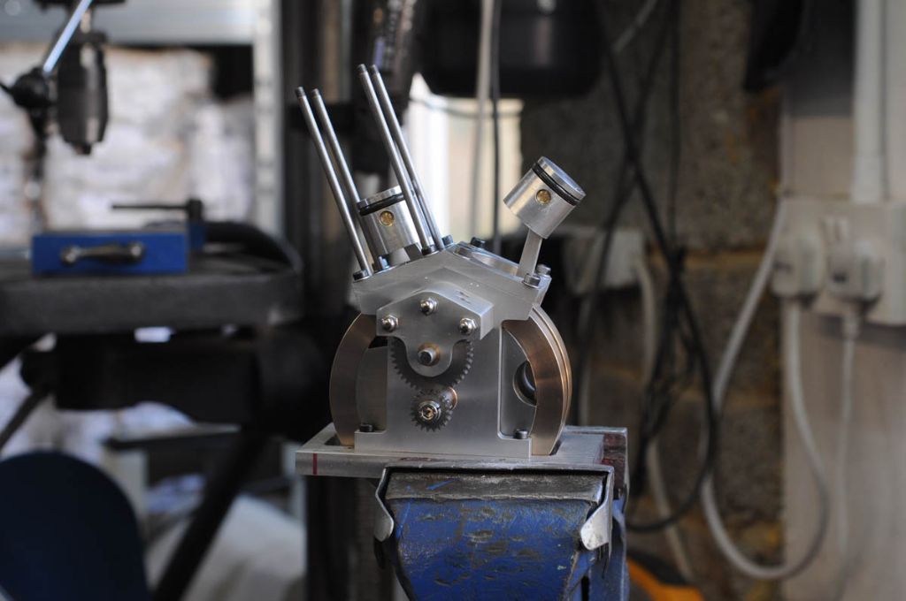
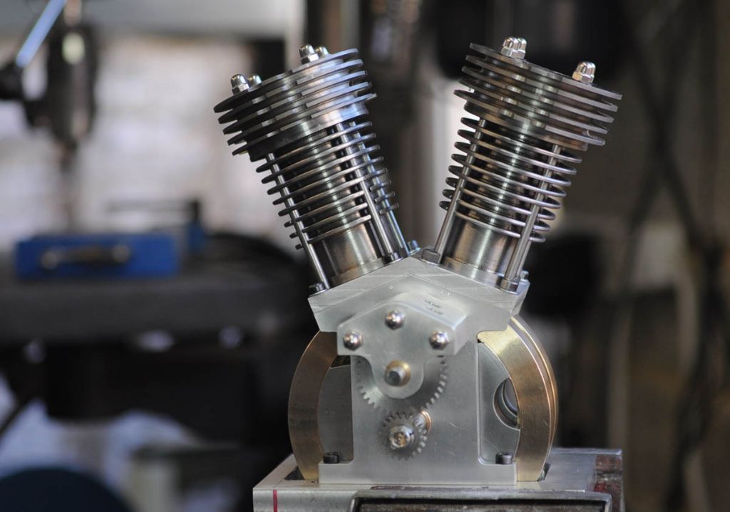
                                              It's beginning to look like an engine. The pistons go up and down and the cam gears mesh smiley

                                              h96.jpg

                                              Thanks for looking in,

                                              Rod

                                              #631294
                                              ianj
                                              Participant
                                                @ians

                                                It's looking good Rod.

                                                I finished mine some time ago, but having trouble sourcing the RCEXL V twin ignition, They are out of stock at "just engines". Plenty of the single hall sensor ones available but I can't find the two sensor type .


                                                Just to add I secured the crank pins on mine using grub screws threw the the crank webs.

                                                Edited By ian j on 29/01/2023 22:09:53

                                                #631310
                                                Roderick Jenkins
                                                Participant
                                                  @roderickjenkins93242

                                                  Ian,

                                                  How frustrating. It looks like Minimag may have a solution:

                                                  Minimag

                                                  Cheers,

                                                  Rod

                                                  #631317
                                                  JasonB
                                                  Moderator
                                                    @jasonb

                                                    Yes you only need a single sensor and if using a double would need to find a way to stop one picking up the magnet for the other. I have an S/S ignition with single sensor and twin coils but Roy is retiring so unlikely to be available now. I also don't like the heavy braided wire on the Rcexl ones.

                                                    It's looking good Rod

                                                    #631320
                                                    Roderick Jenkins
                                                    Participant
                                                      @roderickjenkins93242

                                                      I think the RCEXL system ( I havn't played with it yet) uses a pair of sensors that respond to different poles of the magnet so one magnet is installed N facing the sensor and the other S facing.

                                                      Rod

                                                    Viewing 25 posts - 26 through 50 (of 103 total)
                                                    • Please log in to reply to this topic. Registering is free and easy using the links on the menu at the top of this page.

                                                    Advert

                                                    Latest Replies

                                                    Viewing 25 topics - 1 through 25 (of 25 total)
                                                    Viewing 25 topics - 1 through 25 (of 25 total)

                                                    View full reply list.

                                                    Advert

                                                    Newsletter Sign-up