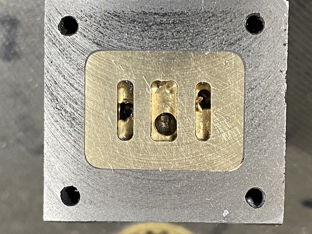
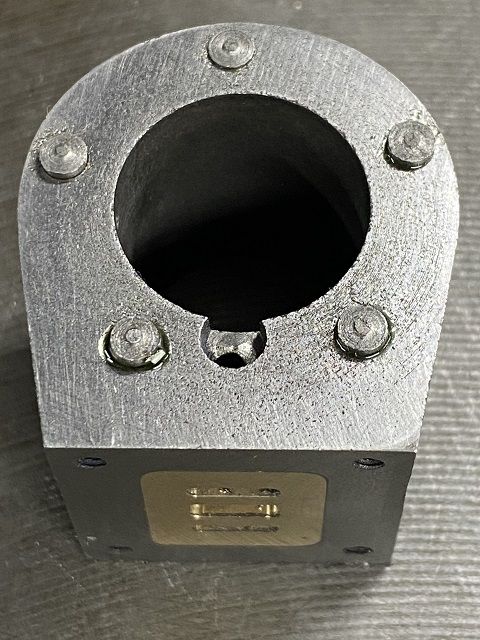
JBWelded the insert in yesterday morning. Looked at it at 8 in evening and had not gone off. Had left it compressed in the flypress in workshop. Obviously not warm enough. Found suitable machine clamp and clamped it together and left on bathroom radiator for 10 hours. That cooked it.
Into the mill and ran facemill over the top. The drilled guide holes through the brass into the casting at points coinciding with original exit of diagonal hole. Set up at 25 degrees and drilled through from end of cylinder to meet up with drilled hole. I had cleaned the echaust pprt up as much as possible before the JBWeld had gone off and ran a tap back down it. Set it up in mill and ran a long centre drill down to meet up with drilled hole.
Pretty happy with the end result. Just needs lapping.
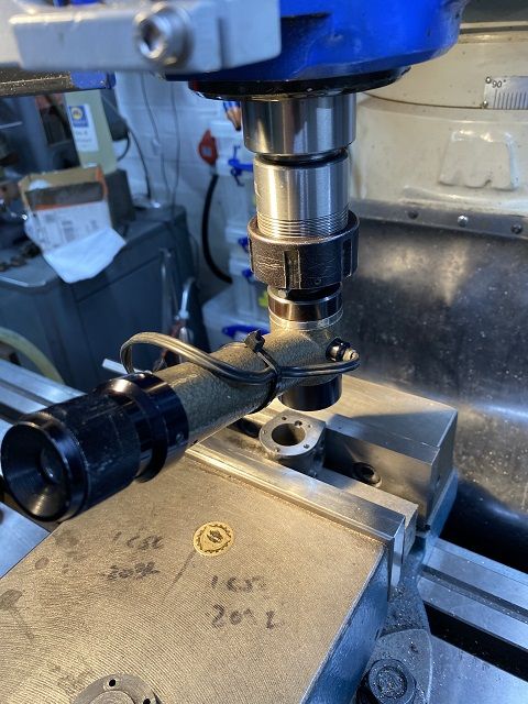
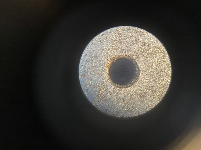
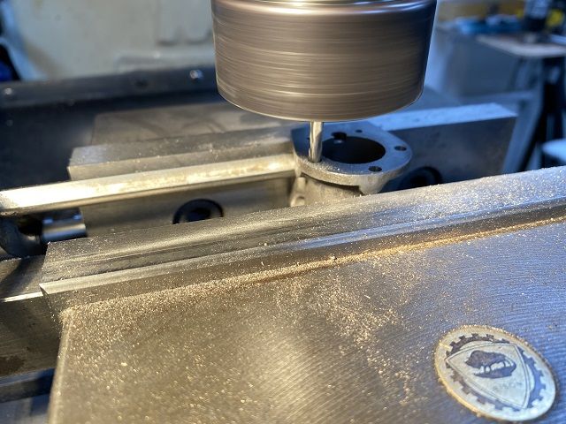
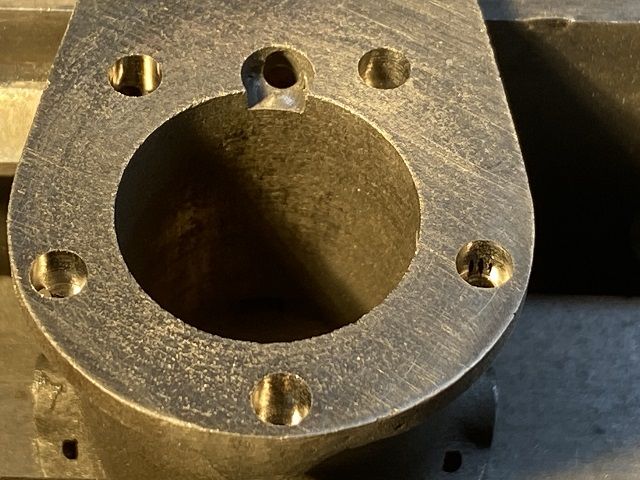
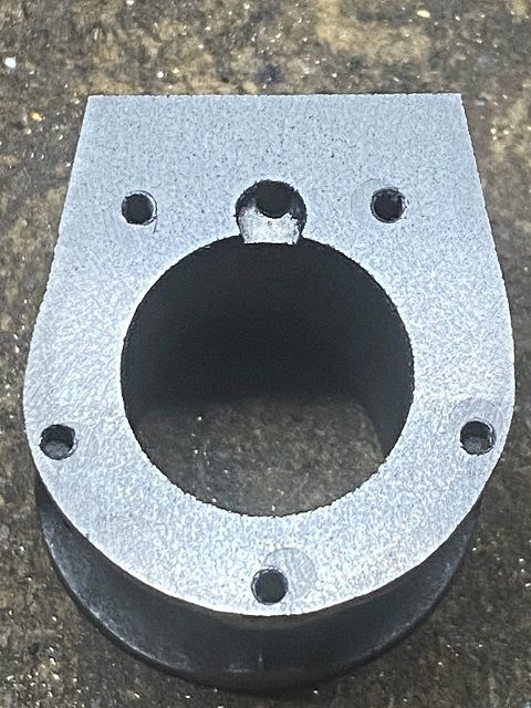
In the end I opted to use a 3.5mm slot mill to remove the 5 tapped holes for the top cover. Before i did this I hunted high and low for some cast iron remnants to use to plug the holes. Eventually found a 20mm length left over from the spigot on the cylinder for the CHUK2 I had recently made. It was 20mm diameter and had a hole in one end. Was it going to be enough. I slit it lengthways to give me four triangular sections 20mm long. Was able to roughly centre this in the three jaw chuck and the checked whether it would stand a interrupted cut and took one piece down to 5mm dia, Happy I could do this I the set the cylinder up in the mill and because I could not trust that the holes were on an accurate PCD I set each hole up one by one with Isoma optical centre.
The swapped to 3.5mm slot drill and took first hole down to 4mm depth. At this point I finished turning the cast iron down to just over 3.5mm dia and checked fit in hole. All okay so repeated exercise for each hole in turn. End result below.
I turned my bits of cast iron down for each hole in turn. I found that the slot mill cut slightly bigger in couple of cases so took the rod to 3.55mm.
Loctited pegs in place and have left on radiator overnight.
Will clean up (and square up) top of cylinder tomorrow and if necessary make a new top cover. Might bling this up and do it in brass.
If you look at the photo half way down previous page you can see the holes which connect to the standard. These are out slightly but nowhere near as far as these were. I think with the top corrected this will not be anywhere as near noticeable, especially with reversing gear fitted.
Colin
I was thinking more for function than aesthetics – the centre of the valve chest boss should be over the axis of the crankshaft, otherwise the valve rod mechanism could bind. Still, you had it running, so it can’t be too far out, if at all.
I like that. Maybe a shade darker and bit of satin varnish on the wood, but yeah. I do like it.
Planning to do a wooden parquet floor for the Princess Royal base, just to add a bit more interest and to help scale it.
Same colour scheme on the engine and beds as the 10V.
Can't quite remember where, I think maybe one of Jason's engines but the wooden floor was run diagonally across the base which I thought looked really good and different to, just a thought.
Left the Loctited inserts overnight on radiator to cook and go off.
In the mill this morning to face down and square the top face to the port face. Then used Bolt Hole on DRO to position the new holes and tap them 7BA. Think they look a lot better. Manage to get the top cover to fit by opening up the clearance holes.
Lapped the port face and cylinder end faces and did a quick reassemble and test run.
A significant difference. Turned the air down to 25psi and would still run. I know this is still quite a lot but not plumbed up properly as yet just using airline nozzle, so losing a lot of air.
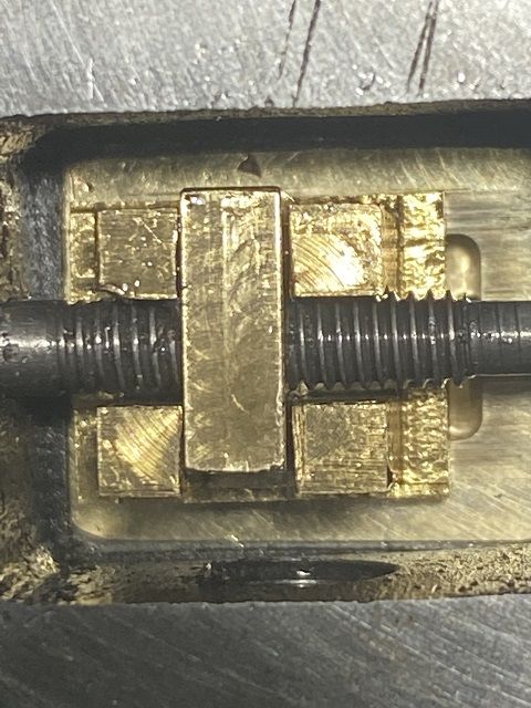
One thing interests me. How much of the inlet ports should be exposed when the slide valve is at the limit of its travel. If you look at the picture below I would say that around two thirds is exposed. This is the same for both extremes of slide valve travel. Would I be correct in saying all of the port should be exposed for best performance. My thoughts are that the slide valve is fractionally too long and needs a quick skim of each end.
Just check the valve is 1/2" long, it won't uncover all the port but the area exposed will be greater than the area of the drilling into the end of the cylinder so that's where the restriction is. Probably about 1/64th left uncovered.
I have now got the engine painted and rebuilt but I am really struggling to get it to run. I have had it running a couple of times but it did not appear to be running very fast. Have tried air pressure at anything from 30 to 80psi.
At the moment I cannot get the slide valve in any position where it is 1/2 and 1/2 over the two inlet ports. 2/3 and 1/3 is the nearest I can get. I will try tomorrow to swap the valve end for end to see if lines up any better.
To set it up I am turning the flywheel to get the piston to TDC. Undoing the screw on the eccentric, rotating the eccentric anti-clockwise (as I look at it) so it is moving in same direction as the flywheel and rotating it until the slide valve is just starting to drop and uncovers the upper inlet port about 1/2mm. Then locking up the eccentric locking screw. Checking that the slide valve appears to be opening at the same time both a TDC and BDC. Bolt the valve chest cover back down. Connect to airline. And nothing. Twice I did get it to run but as I said to my mind it was slow. I then released the eccentric set screw and moved the eccentric a gnats whisker forward or backwards. Then try again. In some positions you can feel the flywheel want to spin, but it does not. If I then put the eccentric back to the position in which I had it running (albeit slowly), It will not run again.
I have spent about 6 hours trying to get it to run and am rapidly losing patience with it. The couple of occasions it did run I could stop the air, reapply the air and it ran. But I cannot find that sweetspot again.
What am I doing wrong? I was under the impression that the eccentric could be moved around a little to and the engine would behave differently depending on how much lead there is on the valve. This thing appears to want to run in one position only and this has to be accurate to a few thou and I only appear to have found this by a fluke on the couple of occasions it has run.
It needed a few changes. I took the top cover off to be able to check getting air and the slide valve working okay. Getting air quite happily whilst piston at TDC and stopped once piston down towards BDC. As soon as the lower port opened I was getting just as much air as from the top port but in this case it was coming round the piston. I knew it was a bit loose but not quite that bad. Tried a 3/4" reamer in the bore and it fell through. Tried a telescopic bore gauge and had a bore of 19.332mm and not only that it tapered from one end to the other. The piston was extremely loose. The only way I could fix the bore was a 23/32" – 25/32" adjustable reamer. Eventually ended up with parallel bore at 19.43mm. New piston turned, lapped briefly to ensure reasonable fit and clear a slight high spot in centre of the bore and then fitted.
When I re-assembled the engine I checked the slide valve and by rotating 180 degrees I had an equal opening of top and bottom ports. Then went with JasonB and Chris's (on MEM) comments regarding opening of the ports. Put to TDC and rotated eccentric so that port did not start to open till piston over TDC. Finished re-assembling and put some air in. It started immediately. After 5 minutes stopped it and disconnected the air and squirted a bit of oil down the inlet. Started it back up. Now after about an hour with stopping it every 15 minutes of so for oil I have got it running very slowly on about 4psi. Really pleased.
Yes it certainly has had its issues. But got there in the end I'm p[leased to say. Very happy with it. Will now add reversing gear and a base. Then try it on steam. I have a number of other casting sets (including various Stuarts) awaiting build as well as some hit and miss and hot air engines. Think I will possibly do an Alyn Foundry Sphinx or RLE next.
Run for over hour and half now. Really loosened up. Have it running with air pressure know set to zero and inline air valve on manifold half open. Runs nice and slow.
Great result – always nice to bring something like that back to life.
Thanks for documenting it – I'm sure it will be useful for folks who are restoring old engines, or even those of us who make mistakes and need to correct the odd hole position!
Just a bit of additional info: I mentioned earlier that the crosshead on mine protrudes very slightly from its guide at the bottom of the crank stroke. I thought this was a machining tolerance error on my part.
I’m reading a book on traction engines, and according to that, this is intentional, the reason being to avoid a step being created by wear, at the bottom of the guide.
One would also have a step at the top on full size, though no reason not to add it to a model too and not just on trunk guides, the bar guides on something like the Voctoria could also be done with a run out at each end.
I have inherited a Stuart 10V unfortunately it is in a bit of a sorry state due to badly made parts etc.
I would like to refurbish this engine and remake a number of the parts correctly including the plugging of wrongly drilled holes.
In order to proceed, I will require drawings of the parts so that I can know the correct dimensions.
Does anyone know where I can source these plans, recommend a book or where I can aquire a scanned copy just something to give me all the correct dimensions?
Thanks for the links, on looking into what I have found up to now I think the best way to go is by purchasing the book as I believe there will be more information and any size errors should be noted in the book also it's cheaper lol.
Now all I have to do is identify and purchase replacement material for the many duff parts, should be fun.
I might keep a log of it all on here my errors in the rebuild might just save someone else.
One issue may be that the updated/reprint book may use metric and your engine was built in imperial.Trying to use one system on another could be problematic. My 1995 copy has both dimensions but I'm not sure you could mate a metric part to an imperial one ! Good Luck. Noel.