Resurrecting a Stuart 10V

Advert

Resurrecting a Stuart 10V

Home Forums Work In Progress and completed items Resurrecting a Stuart 10V

Viewing 25 posts - 1 through 25 (of 76 total)
  • Author
    Posts
  • #523164
    Colin Heseltine
    Participant
      @colinheseltine48622

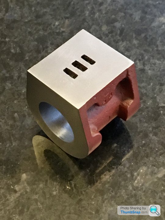
      Many moons ago I bought a built Stuart 10V on Ebay. When it arrived I had a quick look and due to work commitments it got put on one side. I have recently finished two of the Alyn Foundry engines and then saw Dr_GMJN's build of his Stuart 10V and this prompted me to take a look at the one bought a few years ago.

      I quickly found a few problems. The main bearing bolts on one side were loose, so I tightened them up. Bad move, engine locked up completely. Decided to strip it completely, repair any issues, add a few bits and paint it.

      The bearings were a major problem, they had been drilled completely out of alignment and needed 25 thou of shims underneath both the flanges on one of the bearings. Also found he had filed the base and the sole plate but not very squarely and the locations of the bolts for the main bearings were all over the place. Some things I would have to live with others would be fixed. New bearings extrusion ordered, along with valve chest cover, drain valves etc. along with small 7ba nuts. Also 5BA and 7BA taps and dies.

      Whilst waiting for the bits to arrive I started on the steam chest. The slots in the steam valve for the fixing nut were filed but not square and to depth. Also the nut was tapped at an angle. Bit of work with a 3mm slot mill in the Cowells Mill saw the looking a lot better a new nut was fabricated and tapped. The steam chest had also been fitted back to front and had an out of square piece of gauge plate for a cover. By now the ordered parts had arrived and so I machined up the new cover. Started this on the Cowells with a flycutter but it was so chilled around the edges I migrated to the big mill and used a carbide facemill.

      The cylinder and end covers appeared to have been made quite well and all I did with these was drill the cylinder for drain valves.

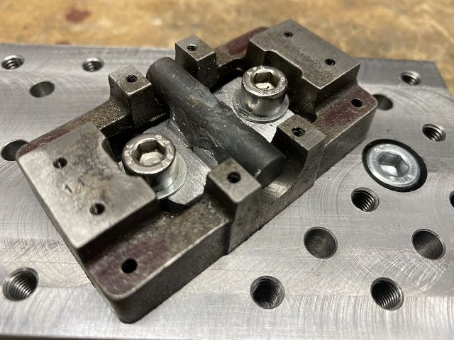
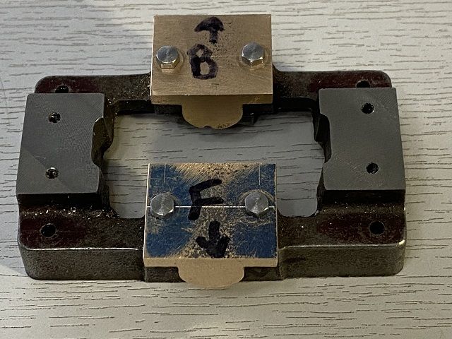
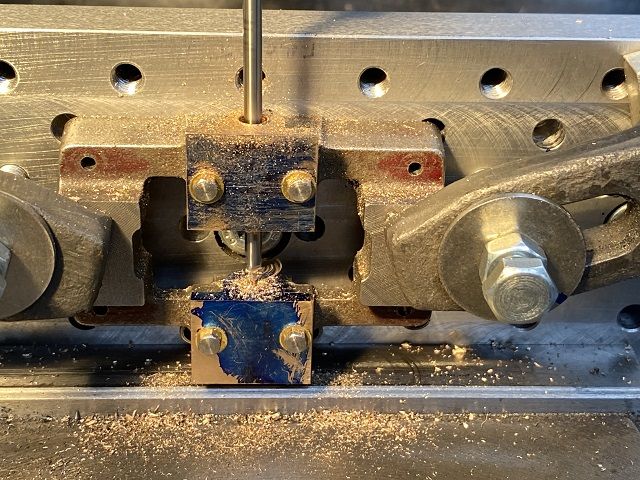
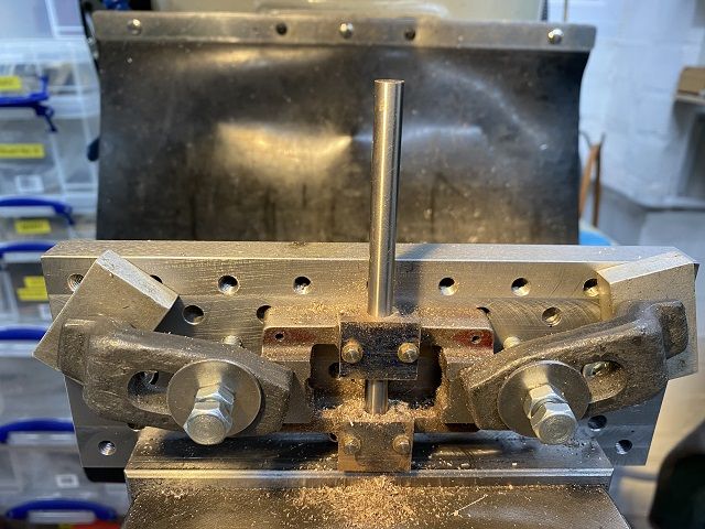
      In one of my other post you can see a fixture plate I made to use initially on this engine. I was able to clamp the soles plate down and facemill the bearing platforms and the standard mounts to get them all level.

      fixturesoleplateres.jpg

      Then flipped the casing over and flattened the bottom. I used the same clamp but files the bar so that it would fit between the lower inside of the casting and and not be proud of the top of the base whilst being machined.

      Colin

      Advert
      #31341
      Colin Heseltine
      Participant
        @colinheseltine48622
        #523283
        Colin Heseltine
        Participant
          @colinheseltine48622

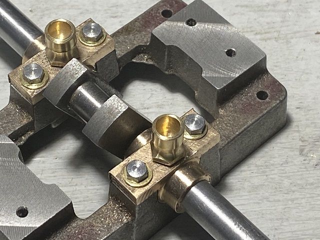
          I felt was going to have difficulty doing the bearings in the normal way by drilling/reaming or boring them in lathe and the turning the bosses down and then trying to fit them onto poorly aligned bolt /stud holes.

          I elected to fit them to the sole plate first, would rill/ream whilst fitted to the sole plate, then remove and turn bosses to length etc.

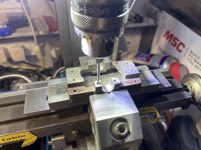
          I started by putting the sole plate in the vice and using the DRO on the Cowells to locate the co-ordinates of all four existing holes.

          bearingco-ordsres.jpg

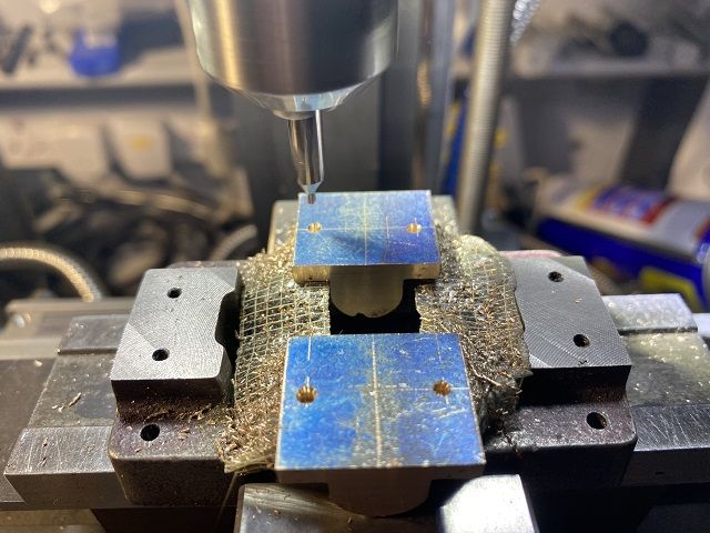
          When I had noted these down I fixed (use this word advisedly) the bearing in place with carpet double sided tape and spotted the holes with a centre drill.

          spottingholesres.jpg

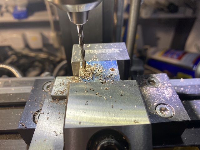
          All appeared great so far. Removed the bearings and then used 1mm pilot drill to locate the bearings in vice to drill the holes to 7BA clearance.

          openingholesres.jpg

          One worked perfectly, the rear bearing had moved and one hole was offset by around 1/2 its diameter in two directions.teeth

          I pondered this for a while. Do I get spare casting and start over or attempt repair. Opted for the repair. The 7BA clearance should be 2.55mm but I had done it at 2.5mm. I turned a short brass pin 2.52mm dia, Loctited the hole and used a punch to drive the pin into the hole then left on a radiator to go off for an hour. Reset the sole plate inthe vice and re-checked the co-ordinates of the holes. This time I was able to use one bolt to hole the bearing firmly in place whilst drilling the 1mm pilot hole. Removed when drilled and opened up to size.

          Both bearings now fit and are held down by bolts.

          bearingfittedres.jpg

          Next task to mount vertically on an angle place and drill ream the hole for the crankshaft.. What can go wrong??

          Colin

          #523795
          Colin Heseltine
          Participant
            @colinheseltine48622

            Was going to use angle plate and mount the fixture to it, but realised did not need the angle plate, just had to but fixture plate on edge in vice. All was square so centred on the middle of the bearing and went through upper bearing with centre drill and then with 3mm drill followed by 6mm drill. At this point I stopped and fitted long center drill and checked was still on centre in lower bearing.

            centredrill2ndbrngres.jpg

            All was okay so put 3mm and 6m drill through the lower bearing. Followed this with 9.8mm drill through both together. Followed this with 9/32" reamer. Then tried 9/32" drill blank. It fitted. smiley

            brngsinlineres.jpg

            Removed the bearings and then made small mandrel to hold the bearing by the bore. Used the Cowells lathe and turned the bearings down to final dimensions.

            Refitted bearings to the sole plate to drill for pair of oil cups. Where are the b….y cups. I had them two weeks ago. Searched high and low through workshop and office. No sign whatsoever. Just about to order some and then decided to make my own. Again used the Cowells lathe as can work in the office in the warm at eye height.

            When happy with a pair I drilled and tapped the holes in the bearings.

            brngs&oilersres.jpg

            Now to sort a few studs out.

            Colin

            Edited By Colin Heseltine on 30/01/2021 21:31:51

            #523813
            Roger Best
            Participant
              @rogerbest89007

              Great start.

              Another good advert for not buying someone else's mistakes. wink

              #523965
              Dr_GMJN
              Participant
                @dr_gmjn

                Nice to see another 10V on here.

                From memory, I did all the boss o/ds, and turned the main bodies to soleplate width on the lathe, but bored the crank hole slightly undersized. The bosses were left long.

                Then you can drop them into the soleplate, and clamp them firmly in place with a bit of bar. Then drill the mount holes and tighten them down with bolts. This being their finished position.

                Then mount vertically, aligned with the drill I used to bore them undersize, and made sure I could freely move the head up and down with the drill in the bores. Then in the same setup, finally drill and ream them to finished size.

                The bosses were then machined to length using the outside of the crank webs to get the right width between them when fitted.

                Anyway, it looks like yours turned out well.

                #524029
                Colin Heseltine
                Participant
                  @colinheseltine48622

                  Dr_GMJN,

                  My problem was the fact that the bearing mounting bolts were not very well placed which Is why I fitted the bearings and bolted them down before drill/reaming.

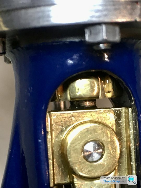
                  I have now come across another little problem. Having machined the sole plate flat this has now lowered the cylinder by six or seven thou. The piston now hits the top of the cylinder and prevents the crank from going over centre.

                  I have the "Building a Vertical Steam Engine" book but I think there are a few errors in it. On page 64 it gives the length of the piston rod as 45mm PLUS the 4mm and 6mm threaded portions giving total of 55mm. The plain section on this engine is approx 37mm long. Because of this the piston bottom is 2mm above the inner face of the lower cover. I have a feeling that 45mm in the book is the overall length and the plain section should be 35.719mm (1 13/32&quot not 45mm.

                  I think I am going to have to shorten the piston rod by around 1.5mm.

                  What is the clearance between the top of the cross-head and the bottom of the piston gland. This looks very close. Again I think I am going to have to take a 0.5mm skim of the top of the cross-head to bring it down to the 10.5mm given in the book.

                  Colin

                  #524031
                  JasonB
                  Moderator
                    @jasonb

                    It's 1 13/32" on the imperial drawing between Crosshead top and bottom of piston.

                    #524035
                    Colin Heseltine
                    Participant
                      @colinheseltine48622

                      Jason,

                      Thank for that confirmation. This piston rod is 1.443", so it is 37thou too long. (just under 1mm too long). Plus the piston rod sticks out of the top of the piston by another 10 thou.

                      Another minor issue is that the piston rod gland nut does not screw fully down. The hole is not fully tapped, had a lot of packing in it. But the cross-head is very close. If I can get a tap then can deepen the hole little deeper, put a bit less packing in and the cross-head will then clear.

                      Fixing someone else's poor work takes a little longer than you would think.

                      Colin

                      #524044
                      Dr_GMJN
                      Participant
                        @dr_gmjn

                        Colin, the crosshead on mine is close to the gland nut, but then again it depends how far it’s screwed in:

                        At the bottom of the stroke the crosshead is a bit below the standard:

                        I’m guessing it should be flush, or a bit above, but it is what it is.

                        I understand now about the bearing holes. I think having read of the amazing powers of JB Weld on here, Id have filled the existing holes with it and started again as if it was untouched metal.

                        You mentioned the steam chest being fitted back to front – mine’s symmetrical.

                        #524237
                        Colin Heseltine
                        Participant
                          @colinheseltine48622

                          With the mods to the piston rod and the gland nut thread in the bottom cover I temporarily assembled the engine this afternoon. Had a few issues with it locking up when tightening the nuts on the valve chest but eventually sorted this and finally had it running briefly with the air line nozzle blowing into the inlet port.. Gradually speeded up as it freed up. Ran it for about 5 minutes, it was a lot better after squirted some clock oil into the steam chest.

                          Will now sort out the cladding and pipework. Whilst i am painting it I can continue with the reversing gear.

                          Colin

                          #524256
                          Dave Wootton
                          Participant
                            @davewootton

                            Nice work Colin, always interesting to see how others overcome these sort of problems with previous builders work, thanks for posting. I've been sorting out a part built locomotive chassis and posting on here,don't know about you, but I find it stimulates the brain no end trying to work out how to put it right. Like the little fixture for holding the soleplate casting, right up my street!. Keep up the good work and please keep posting.

                            Dave

                            #524558
                            Colin Heseltine
                            Participant
                              @colinheseltine48622

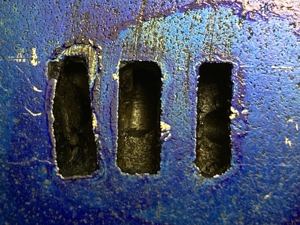
                              img_9211.jpg

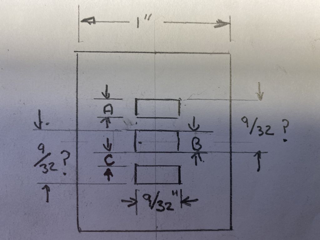
                              Does anyone have the exact port dimensions for a Stuart 10V or more particularly the depth. The ports on this one I am attempting to resurrect are not cast very well. especially the lh one in the picture above. I am not sure how they are would effect the running of the engine if they are left as is. Is it worth filling the left hand port with JB Weld and then re-machining to the correct size/location. The only dimension I can find anywhere on the plans is the width of 9/32". I assume because the slide valve is recess is 9/32" long then the distance between the outer edge of an inlet port and the outer edge of the exhaust port should also be 9/32".

                              The dimensions I would like to confirm are shown as A,B and C in the drawing below.

                              img_9212.jpg

                              The engine turns over quite easily by hand. It does not appear to be tight anywhere. The piston is very free in the bore (maybe too free). BUT It needs a quite high PSI to get it to run.

                              Thanks,

                              Colin

                              Edited By Colin Heseltine on 03/02/2021 16:38:33

                              #524560
                              Former Member
                              Participant
                                @formermember12892

                                [This posting has been removed]

                                #524561
                                JasonB
                                Moderator
                                  @jasonb

                                  It's in your 10V book Colin.

                                  Who said the old castings were the bestdevil

                                  Edited By JasonB on 03/02/2021 16:51:03

                                  #524565
                                  Former Member
                                  Participant
                                    @formermember12892

                                    [This posting has been removed]

                                    #524567
                                    Colin Heseltine
                                    Participant
                                      @colinheseltine48622

                                      Jason,

                                      Certainly not on page 22 Fig & cylinder in my book. But my eyes have finally found it on the drawing you sent. Having stared at it for some length of time.

                                      The exhaust port is only 3/32". The gap between the lower inlet and the exhaust varied from 1/32" to 1/16"

                                      The upper inlet is correct as regards distance from exhaust and its width.

                                      What would be recommendation to correct.? Preferably not scrap it.smiley

                                      Colin

                                      #524570
                                      JasonB
                                      Moderator
                                        @jasonb

                                        One option would be to mill out a recess say 1/16" thick to just beyond the area that the steam chest covers and JBWeld in a plate that could be cut from brass. Mill the ports in it first rather than risk having to remove it if something goes wrong while machining in place.

                                        #524571
                                        Former Member
                                        Participant
                                          @formermember12892

                                          [This posting has been removed]

                                          #524572
                                          Colin Heseltine
                                          Participant
                                            @colinheseltine48622

                                            Thanks Jason and Br.

                                            Need to have a think?

                                            Colin

                                            #524575
                                            Dr_GMJN
                                            Participant
                                              @dr_gmjn
                                              Posted by br on 03/02/2021 17:00:42:

                                              Posted by JasonB on 03/02/2021 16:50:02:

                                              It's in your 10V book Colin.

                                              Who said the old castings were the bestdevil

                                              Edited By JasonB on 03/02/2021 16:51:03

                                              ME.

                                              br

                                              This was my new fangled casting after the port face was fly cut:

                                              Didn't do any further work on the ports and it runs OK.

                                              #524580
                                              Former Member
                                              Participant
                                                @formermember12892

                                                [This posting has been removed]

                                                #524591
                                                Colin Heseltine
                                                Participant
                                                  @colinheseltine48622

                                                  Having had a much closer look and spotting some "white stuff" in the miss-shaped port it looks as though there is a small blow-hole between the exhaust port and the miss-shaped inlet port or more likely when drilling the port through from the end of the cylinder it was drilled too far. It has possible had some filler put in somehow. Looks like it will definitely have to be the brass insert.

                                                  I think the insert will have to be at least 1/4" thick as it is now going to have to replace the port slots in their entirety.

                                                  angry

                                                  Colin

                                                  #524599
                                                  Dr_GMJN
                                                  Participant
                                                    @dr_gmjn
                                                    Posted by JasonB on 03/02/2021 17:13:30:

                                                    One option would be to mill out a recess say 1/16" thick to just beyond the area that the steam chest covers and JBWeld in a plate that could be cut from brass. Mill the ports in it first rather than risk having to remove it if something goes wrong while machining in place.

                                                    What would be the issue with filling them with JB Weld?

                                                    Different wear rates when the slider moves over that area?

                                                    Could also stick a drill shank down the port holes before it set to avoid re-drilling them?

                                                    #524605
                                                    JasonB
                                                    Moderator
                                                      @jasonb

                                                      JBW would probably work OK too, just give the surfaces a once over with a small burr in the dremel to key them and also remove any traces of old oil. Then machine the ports again once set.

                                                      I doubt the JBW would wear down as most of the valve will be sitting on the surrounding cast iron

                                                    Viewing 25 posts - 1 through 25 (of 76 total)
                                                    • Please log in to reply to this topic. Registering is free and easy using the links on the menu at the top of this page.

                                                    Advert

                                                    Latest Replies

                                                    Viewing 25 topics - 1 through 25 (of 25 total)
                                                    Viewing 25 topics - 1 through 25 (of 25 total)

                                                    View full reply list.

                                                    Advert

                                                    Newsletter Sign-up