Replacement motor control box for mini mill

Advert

Replacement motor control box for mini mill

Home Forums Electronics in the Workshop Replacement motor control box for mini mill

Viewing 22 posts - 1 through 22 (of 22 total)
  • Author
    Posts
  • #521168
    andrew lyner
    Participant
      @andrewlyner71257

      Needing to replace a motor speed controller seems to be 'not uncommon'. The motor on my Sealey SM2502 stopped working after I tried using a 65mm slitting saw. The motor is OK because it works with 12V DC (Slowly but with plenty of torque.

      I examined the control board and it has no signs of frying any components. I poked around with my Scope and, apart from the rectification of the input mains supply, it was too hard to trace any fault – apart from no output.

      I'm tempted to try a twenty quid controller from eBay, which is ok of a 300W DC brush motor at 230V. I could try replacing the major active devices and the capacitors but it could easily cost me a lot of fruitless effort and the cost of the bits. I can't find a schematic diagram either, which makes it doubly difficult.

      I understand that quite a few people have gone down this road, rather than paying a lot of money for a manufacturer's replacement. Are there any lessons to learn? I was wondering if some extra protection in the form of a MCP breaker might do the job as the available cheap boards don't claim to have any (afaics).

      What's my chance of success? I really don't want to be without the Mill for longer than necessary.

      Advert
      #32165
      andrew lyner
      Participant
        @andrewlyner71257

        To go for a cheap replacement or not to go.

        #521197
        John Rudd
        Participant
          @johnrudd16576

          Without knowing your level of expertise, its difficult to pitch a guide of what to check.

          Which board do you have in your mill? I doubt it will be a Sieg board ( unless Sieg supply the machines and Sealey rebadge them..) so that leaves KB Electronics/Best….The Best unit being a chinese clone of the KB board…

          The cheap £20 controllers from ebay may not work….if it is a triac based unit….the motor is a PMDC motor not a universal motor, so wont like chopped AC up it…and being cheap, the circuitry is unlikely to have any form of overload protection or load compensation unlike the original, but if you're happy to forego these niceties then you could just add a suitably rated bridge rectifier to the output of the cheap ebay unit as Proxon did…

          #521208
          nigel jones 5
          Participant
            @nigeljones5

            gave mine to our super elec tech at work to fix (bloke is a genius) and he couldnt fix it! Mine now has a drill motor with no speed control but at least its super reliable.

            #521248
            andrew lyner
            Participant
              @andrewlyner71257

              Many thanks for the input so far.

              The board is an XMT 2335 and has 'Seig' marked on it. The mill seems to have much in common with the Seig.

              I will check the motor to see if it's a Universal. I guess a PM would reveal itself to a steel screwdriver. It looks a pretty ancient design and a conventional shape. 7Ohms resistance when stationary.

              If it doesn't run convincingly with a cheap controller, I can always buy a bridge rectifier.

              #521258
              andrew lyner
              Participant
                @andrewlyner71257

                Ahh, it seems to be a PM motor, from a quick Google search!.

                #521264
                John Haine
                Participant
                  @johnhaine32865

                  I recommend a KBIC speed controller. My Novamill came without a controller, it has a 180V DC brushed motor so I used one and it works well and is bulletproof (so far). Yes I have crashed a running cutter straight into metal and the fuse blew but the silicon survived. There are also Chinese controller off eBay some of which have been successfully used. The kind that come in a perforated metal box with terminal block and a separate speed control pot are best – these generally also have a field winding feed since some of these motors have wound field.

                  #521266
                  noel shelley
                  Participant
                    @noelshelley55608

                    You have a scope ! use a meter and track the power, if it stops at a triac or similar device it might be worth checking the device or replace it.  but remember you may be dealing with 240v ac. Noel

                    Edited By noel shelley on 20/01/2021 12:30:25

                    #521267
                    andrew lyner
                    Participant
                      @andrewlyner71257

                      My motor (95D-1) iis rated at 220V DC so the voltage from the KBIC will limit top speed somewhat.

                      #521270
                      andrew lyner
                      Participant
                        @andrewlyner71257
                        Posted by noel shelley on 20/01/2021 12:29:09:

                        You have a scope ! use a meter and track the power, if it stops at a triac or similar device it might be worth checking the device or replace it. but remember you may be dealing with 240v ac. Noel

                        Edited By noel shelley on 20/01/2021 12:30:25

                        I do have a scope and it's a very basic second hand analog one but it stands alone without needing a PC display.

                        At least the red box is plastic and the floor is dry wood!! I am scared of Mains – which is good for health.

                        I looked at waveforms and all I could see was AC, then half-wave rectified 0V to – 300V (ish). Nothing else. Perhaps the fact that it's not full wave / bridge rectified suggests there's a diode problem. I'll go out and have another poke around before ordering anything.

                        #521273
                        andrew lyner
                        Participant
                          @andrewlyner71257

                          It would be really handy to get hold of a schematic diagram of this thing. I guess the makers don't want it to be very public.

                          I was always hopeless at getting a diagram from just a PCB and I am totally out of practice now.

                          #521286
                          John Rudd
                          Participant
                            @johnrudd16576

                            Unless you operate with a fully isolated floating supply, “poking around” with an oscilloscope is not a good idea.

                            The 0V rail is referenced at half mains voltage.

                            There are 2 heavy current diodes and 2 similar rated scr’s connected in a full wave bridge configuration.

                            The scr’s are triggered by the low level electronics. If the supply to these isn’t present then the scr’s won’t be triggered at all….Check the 15K 2W carbon resistor adjacent the 0.01Ohm current sensing resistor…..

                            #521288
                            John Rudd
                            Participant
                              @johnrudd16576
                              Posted by andrew lyner on 20/01/2021 12:30:02:

                              My motor (95D-1) iis rated at 220V DC so the voltage from the KBIC will limit top speed somewhat.

                              In general the KBIC controllers I have reworked are usually set to have circa 180V at the motor terminals.

                              There is scope to raise this further, how much further I haven’t tried beyond 200V as most controllers were for use with 180V motors.

                              #521297
                              Les Jones 1
                              Participant
                                @lesjones1

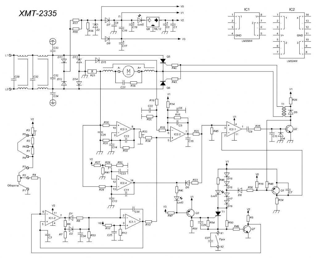
                                Here is a schematic for the XMT-2335 board in case you do not have one.

                                xmt-2335.jpg

                                Arc Euro stock them under Seig X2 spares but they are £136.31.

                                Les.

                                #521352
                                andrew lyner
                                Participant
                                  @andrewlyner71257

                                  Cheers Les. That diagram is very helpful. That sort of circuit is far from intuitive when it pulls itself up by its own bootstraps. I'm just wondering if it could be the speed adjustment pot or its connections. After all, the last thing I did before it wouldn't;t work any more was to use the switch or the pot itself.

                                  In the light of the fact that the board show no signs of heat or damage and there's no funny smell anywhere I can now look at places on the board to check on the paths there and back from the pot. The only annoyance is that I won't be able to look at it till tomorrow pm at the earliest.

                                  #521363
                                  Les Jones 1
                                  Participant
                                    @lesjones1

                                    As John Rudd mentioned DON'T try to use a scope to fault find unless you supply the speed controller from an isolating transformer with a floating secondary. I suggest using a 60 or 100 watt incandescent light bulb as a load in place of the motor connected directly to the board. Also don't forget to link the connections that normally go to the interlock switches.

                                    Les.

                                    #522836
                                    andrew lyner
                                    Participant
                                      @andrewlyner71257
                                      Posted by John Rudd on 20/01/2021 13:53:51:The scr’s are triggered by the low level electronics. If the supply to these isn’t present then the scr’s won’t be triggered at all….Check the 15K 2W carbon resistor adjacent the 0.01Ohm current sensing resistor…..

                                      Spot on – well done – the 15k carbon resistor is O/C. So none of the control circuit gets any power. Is the other resistor in parallel just a backup to keep some bias on the downstream bits?

                                      Actually 2W rating doesn't leave a lot in hand (200V squared / 15K is 2.5W) so a bigger replacement may be a good idea. The way it's mounted implies they expect it to get warm.

                                      Watch this space. I really don't want to have to spend 130 quid plus and I now find that the Sealey replacement part is around 180 quid. I just wonder if the 2335 in mine was a replacement and if the Sealey part (SM2502) is subtly different. Any ideas?

                                      #522951
                                      Pete Savage
                                      Participant
                                        @petesavage40461

                                        I was looking into similar things. My Unimat has a 240v ~95W DC motor with built in rectifier and a 2 speed triac speed control, however I was looking to redesign the system with a circuit from this page here and allow PWM control and hall effect closed loop control, and allow speed control through a GRBL CNC board.

                                        I then thought if I could find a 240v 3 phase motor, and use a small variable frequency drive controlled by 0-5v this would be a much simpler solution, and I wouldn't need the feedback loop, as the frequency in fixes the motor at the RPM so long as it has adequate power. It seems like small 3 phase 240v motors are a bit difficult to find though, and I don't think you can alter frequency on a single phase AC motor without letting the magic smoke out.

                                        #522995
                                        John Haine
                                        Participant
                                          @johnhaine32865

                                          Pete, I've done exactly that with my Unimat – see my album. The motor is a nice small 375W (I think) Parvalux I got on eBay for not a lot of money – new but surplus stock I guess. There are similar ones listed today though not quite the same power **LINK**

                                          I drove it from an IMO iDrive2 inverter – I say drove it because I had to commandeer than to replace the VFD on my mill which developed a fault, but just now I've had a replacement delivered from Newton Tesla…

                                          #523000
                                          John Rudd
                                          Participant
                                            @johnrudd16576
                                            Posted by andrew lyner on 26/01/2021 18:03:24:

                                            Posted by John Rudd on 20/01/2021 13:53:51:The scr’s are triggered by the low level electronics. If the supply to these isn’t present then the scr’s won’t be triggered at all….Check the 15K 2W carbon resistor adjacent the 0.01Ohm current sensing resistor…..

                                            Spot on – well done – the 15k carbon resistor is O/C. So none of the control circuit gets any power. Is the other resistor in parallel just a backup to keep some bias on the downstream bits?

                                            Actually 2W rating doesn't leave a lot in hand (200V squared / 15K is 2.5W) so a bigger replacement may be a good idea. The way it's mounted implies they expect it to get warm.

                                            The purpose of the 100k resistor isnt clear…Its value is too high and its rating too low to be of any useful purpose.

                                            I generally replace the 15K carbon unit with a 5 Watt ceramic wirewound type for a lasting repair…(I've told all my secrets now…)

                                            #523044
                                            Pete Savage
                                            Participant
                                              @petesavage40461
                                              Posted by John Haine on 27/01/2021 10:19:10:

                                              Pete, I've done exactly that with my Unimat – see my album. The motor is a nice small 375W (I think) Parvalux I got on eBay for not a lot of money – new but surplus stock I guess. There are similar ones listed today though not quite the same power **LINK**

                                              I drove it from an IMO iDrive2 inverter – I say drove it because I had to commandeer than to replace the VFD on my mill which developed a fault, but just now I've had a replacement delivered from Newton Tesla…

                                              Ah, that looks like a neat solution, unfortunately I also use it on the milling head too so it really needs to fit the form factor of the original, I was tempted to try a small 3 phase electric motor from an RC plane down below 30v, as you can easily get 500 watt motors in a pretty small package, but it gets messy having to have a high current power supply, or a transformer.

                                              #526515
                                              andrew lyner
                                              Participant
                                                @andrewlyner71257
                                                Posted by John Rudd on 27/01/2021 10:45:30:

                                                Posted by andrew lyner on 26/01/2021 18:03:24:

                                                Posted by John Rudd on 20/01/2021 13:53:51:The scr’s are triggered by the low level electronics. If the supply to these isn’t present then the scr’s won’t be triggered at all….Check the 15K 2W carbon resistor adjacent the 0.01Ohm current sensing resistor…..

                                                Spot on – well done – the 15k carbon resistor is O/C. So none of the control circuit gets any power. Is the other resistor in parallel just a backup to keep some bias on the downstream bits?

                                                Actually 2W rating doesn't leave a lot in hand (200V squared / 15K is 2.5W) so a bigger replacement may be a good idea. The way it's mounted implies they expect it to get warm.

                                                The purpose of the 100k resistor isnt clear…Its value is too high and its rating too low to be of any useful purpose.

                                                I generally replace the 15K carbon unit with a 5 Watt ceramic wirewound type for a lasting repair…(I've told all my secrets now…)

                                                When I replaced that big steaming resistor, the board became even deader – no less lit and at least one chip looking charred. So I decided to get a new board from Arc Euro, (£138 ouch) despite their special email to me with a severe Caveat Emptor message. I carefully transferred connections from one board to the other, checked the operation of switches and the potentiometer (motor was working anyway). Damned thing did nothing when at switch on. Check, check and check all connections (I was getting quite familiar with the circuit by now) Check Volts across diodes and stuff. Finally I looked at the wire link across small green terminal block at the bottom. There was a VOLTAGE DROP across the screws. The U shaped link I had fitted was not making contact under one screw – pushed in behind rather than under the shoe. Sorted and I gave a sigh of relief that I hadn't returned the unit – potential great embarrassment.

                                              Viewing 22 posts - 1 through 22 (of 22 total)
                                              • Please log in to reply to this topic. Registering is free and easy using the links on the menu at the top of this page.

                                              Advert

                                              Latest Replies

                                              Viewing 25 topics - 1 through 25 (of 25 total)
                                              Viewing 25 topics - 1 through 25 (of 25 total)

                                              View full reply list.

                                              Advert

                                              Newsletter Sign-up