Remote starter system – identifying parts

Advert

Remote starter system – identifying parts

Home Forums Related Hobbies including Vehicle Restoration Remote starter system – identifying parts

Viewing 16 posts - 1 through 16 (of 16 total)
  • Author
    Posts
  • #583534
    Oily Rag
    Participant
      @oilyrag

      Gents,

      I am currently involved in the restoration of the engine for a rare car from the early 1990's. The engine uses a remote start system where due to space limitations the starter motor is mounted some way from the rear of the engine. To enable the starter pinion to engage with the ring gear, this starter system uses a long shaft (almost 16" long) with two hook joints and also has a one way sprag clutch onto which the 10T ring gear pinion mounts.

      What I am looking for is a better hook joint than the current pin type system, the type I'm thinking of is the 'ball and claw' type often seen on machine tools (particularly table drives for milling machines ) as I believe this type does not have a very pronounced cyclic speed error.

      The other item I'm looking for is a replacement for the drive sprag clutch into which the starter pinion fits. The motor operates by the usual Bendix gear which moves the pinion into mesh with the ring gear, but it would appear that the sprag clutch is there to protect against a 'backfire' which would (and does!) wreck the long drive shaft from the remote starter motor.

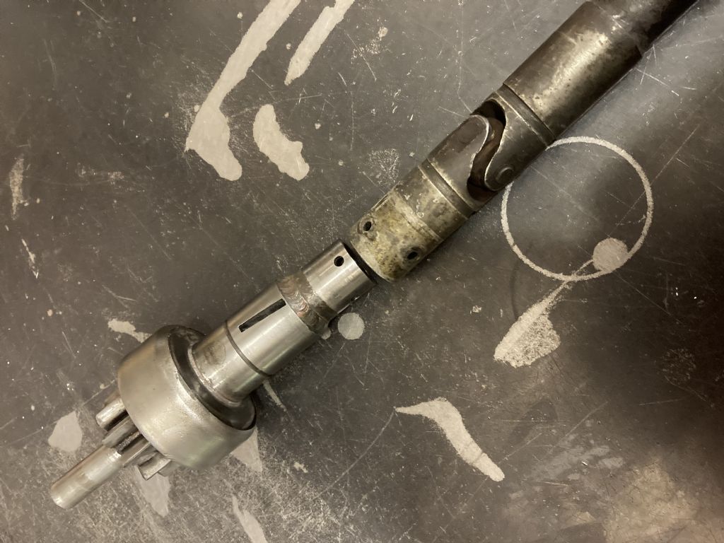
      Here are some pictures of the current parts:-

      img_0220.jpg Flywheel end of the system, shaft is 3/4" diameter.

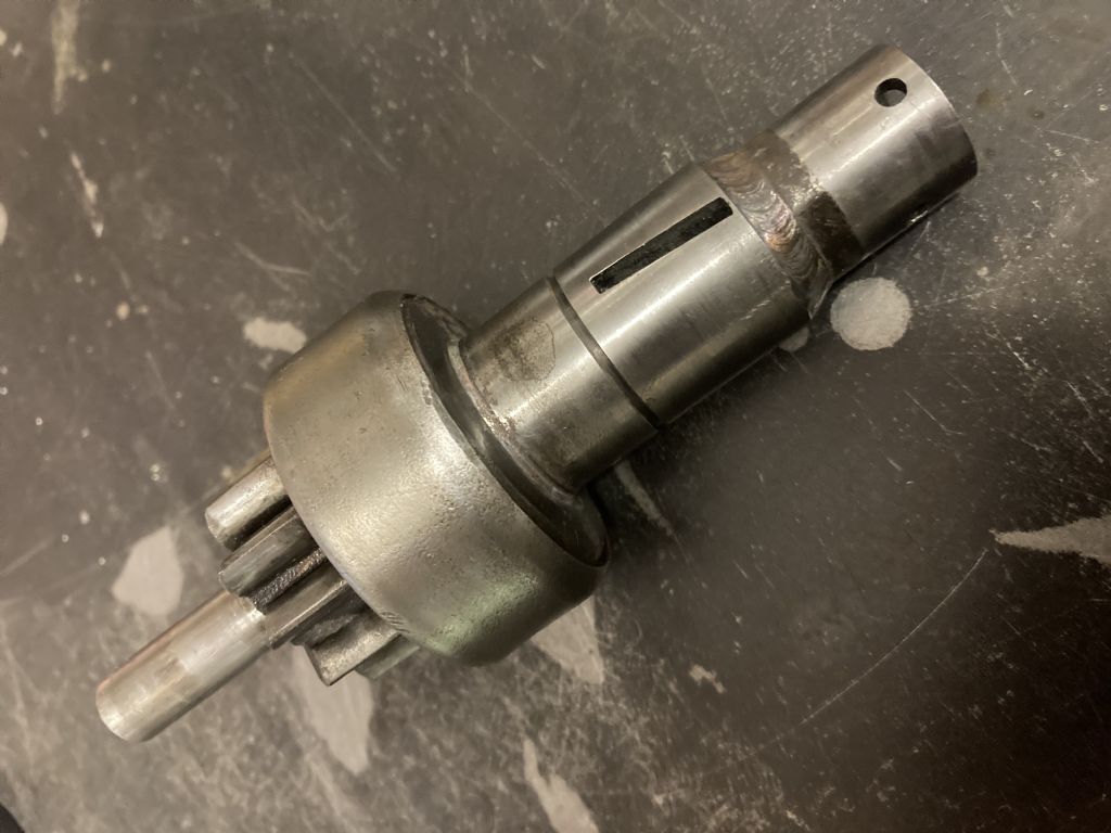
      img_0219.jpg

      The sprag clutch with starter pinion mounted

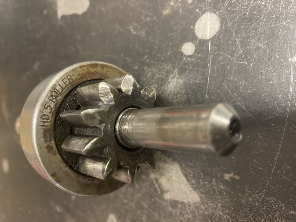
      img_0217.jpg

      End view of the 'sprag' with the only markings on the component

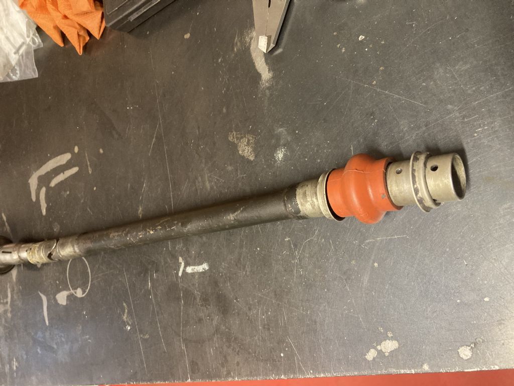
      img_0221.jpg

      The end which connects to the remotely mounted starter motor

      img_0222.jpg

      A view down the length of the block showing the sprag clutch mount in the foreground and the starter motor (mounted by the blue anodised bracket ) in the rear area.

      Thanks for any help / assistance / suggestions / cups of tea / and sympathy offered.

      Martin

      Advert
      #34512
      Oily Rag
      Participant
        @oilyrag
        #583535
        Tim Stevens
        Participant
          @timstevens64731

          Any cyclic speed error, if I understand your pictures properly, will be minimal, and surely nothing to worry about. Any starter has its own cyclic variation because of the compression in each cylinder.

          As to the sprag clutch, I am at a loss to help. If the one you have has failed, there may be room to fit an alternative somewhere in the length – but this would require a firm attachment as the reaction on the clutch if there is a kick-back has to be accommodated. What jolly fun …

          Cheers, Tim

          #583539
          Ian P
          Participant
            @ianp

            At which end of the shaft is the Bendix device?

            If as you state the 10t pinion is mounted on the roller clutch then presumably when the pinion is thrown out of engagement with the flywheel gear the whole shaft (with its significant mass) has to move rather swiftly as well.

            As Tim mentioned cyclic errors in the shaft will not matter a jot assuming the pinion and motor axis are somewhere near parallel (say within 10 degrees)

            Ian P

            #583541
            john halfpenny
            Participant
              @johnhalfpenny52803

              Nothing to be concerned about re cyclic variation. You may find a suitable sprag clutch in an overdrive or an automatic gearbox, though these typically have a rather larger od.

              #583542
              Ian P
              Participant
                @ianp

                I this a pre-engaged arrangement?

                Ian P

                #583547
                Hopper
                Participant
                  @hopper

                  Any clue as to the make and model of the car? Might be helpful. (And enquiring minds want to know!)

                  A wide variety of sprag clutches is available from bearing suppliers. Usually identified by that number on the side. Ditto "Bendix gears" if the gear and clutch are made as one piece.

                  The sprag clutch will not protect against backfire as the backfire force is applied in the direction that makes the clutch engage even harder, just like hitting extra high compression in effect. The sprag clutch is usually so that when the engine starts and the flywheel revolves faster than the starter drive gear, the sprag clutch lets go and the starter motor is not over-speeded as a result.

                  In the absence of a spiral spline or solenoid to move the gear out of engagement with the flywheel ring gear, it looks like that gear is permanently engaged and so the sprag clutch is permanently in operation allowing it to free wheel, so wear on the sprag clutch internals will be fairly rapid. Norton used a similar system on their woeful electric start Commandos and suffered this problem. Nothing much you can do about it other than replace the sprag clutch at suitable intervals, or go to a whole different starter system that disengages the gear physically.

                  #583550
                  noel shelley
                  Participant
                    @noelshelley55608

                    The shaft is more or less in line so the cyclic issue – no issue ! The sprag clutch is there to handle the overrun, not a kickback and looking at the shaft in front of the pinion I assume that is to allow the whole affair to drop back when the solenoid disengages, so yes it's pre engage ? The whole idea is not great, there are some very small hardy spicer type U/Js about but whether using them would improve things ? Since there is so little room I suspect they have used the biggest bit they could fit in ! Good luck, Noel

                    #583553
                    Paul Lousick
                    Participant
                      @paullousick59116

                      Virtually every rear wheel drive car and truck, etc has universal joints in the drive shaft and would have a slight cyclic speed error but does not cause a problem.

                      #583559
                      Jon Lawes
                      Participant
                        @jonlawes51698
                        Posted by Hopper on 01/02/2022 22:45:39:

                        Any clue as to the make and model of the car? Might be helpful. (And enquiring minds want to know!)

                        I dunno but its a fun game to take a stab! Cosworth HB? Judd?

                        #583613
                        Oily Rag
                        Participant
                          @oilyrag

                          Thanks for the many replies Gents!

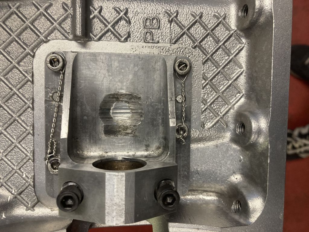
                          Just to define the system a little more – The starter motor is a high performance high torque geared unit, the Bendix scroll is mounted in the end of the starter motor (just visible in the last photo looking down the block ). So, the way this operates is for the motor on energisation to push the whole of the remote shaft forwards and the pinion then engages with the ring gear and spins the engine up. The bracket shown at the front of the engine allows/supports the sprag clutch system and there is also an outer support for the pinion which fits into a bush in the bell housing. The PB bush in the housing photo below is very worn which hasn't helped the shaft alignment.

                          This engine is being restored after it had been 'mullered' by some unknowing mechanics when it was in Japan. The lower hook joint in the system had worn badly and damaged the bracket housing:-

                          img_0214.jpg

                          The damage on the sprag support bracket caused by the lower hook joint.

                          The repair that had been done was that the 4 outer bolts had stripped the threads in the block and the answer they used was to put Nylok nuts on the inside of the block! (which meant the sump had to be removed to access the nuts ) not surprisingly the Nyloks (two of them ) were found lose in the sump when we stripped the engine!

                          We have now Helicoiled the threads and cross drilled and wirelocked the Allen screws. The dowels were also opened up to a larger size and are secured (by step drilling on the inside and by covering them with the lock wire run )

                          The car is a JaguarSport XJR15 road car of which only 42 were made. The engine is a 7.3litre Jaguar V12 (a stroked version of the JaguarSport XJRS 6 litre V12 ). This car was the Chassis development Prototype.

                          We have now identified a suitable sprag clutch arrangement which we can utilise (Reynolds Machine Tool division SO/SX series ) and we think we have found a suitable small hook joint system that has needle rollers. Available from WDS engineering supplies. But I'm still keen to find a UJ which has the ball and claw system. I am in contact with numerous ex colleagues at TWR, so I am getting assistance from their log books as well as my own, all helping to jog a 30 year old memory of these parts. The original UJ's were Dayton #20271 MTX – 5.771 DM. These we believe were American sourced and probably helicopter linkage parts.

                          A further part of the project is to build a replica engine based on this unit as a 'spare'.

                          Martin

                          #583628
                          Oily Rag
                          Participant
                            @oilyrag
                            Posted by Jon Lawes on 02/02/2022 06:53:27:

                            Posted by Hopper on 01/02/2022 22:45:39:

                            Any clue as to the make and model of the car? Might be helpful. (And enquiring minds want to know!)

                            I dunno but its a fun game to take a stab! Cosworth HB? Judd?

                            Ha! Not bad guesses.

                            Although the Cosworth DFV was the first engine in over 60 years to be designed with no visible method of starting it! The HB was started via a shaft up it's a55 (through the gearbox ) as was all the Judd's with the exception of the KV 3000 engine and the reworked ex F1 V10 GV 3.5 litre when opened up to 4 litre for sports car racing and designated the MV. These used a system similar to that as we used on the XJR 15. The hand held starters were either 24V lorry units running off a step up to 48v or 36v after initialisation at 24v. Alternative start systems were compressed air starters with two speed running (to prime and then fast spin ).

                            Martin

                            #583632
                            Roger B
                            Participant
                              @rogerb61624

                              I think the sprag Clutch is there so that if the pinion doese not disengage from the flywheel gear when the engine starts the whole shaft is not driven at some thousands of rpm (depending on the gear Ratio).

                              #583744
                              Howard Lewis
                              Participant
                                @howardlewis46836

                                Likely that the sprag clutch is to protect the starter motor from over speed.

                                The pinion to ring gear ratio will be about 12 or 13:1.

                                The big CAV and Simms starters for Bus engines did not enjoy remaining engaged when the engine was running! They were not designed for 26,000 + rpm!

                                So being run at 100,000 rpm plus would not do the motor or couplings on your engine any good at all!

                                Howard

                                #583769
                                Ian P
                                Participant
                                  @ianp

                                  Going back to the beginning of this thread the OP stated that the drive shaft got (or gets) 'wrecked' under some fault condition. It would be interesting to know what the resulting damage is, i.e. whether pins sheared, the shaft getting bent or something else.

                                  What actually causes the damage to the bearing support bracket? If the pinion shaft carrying the Hooke joint is was well supported then the outer diameter of the Hooke joint would not be able to leave those score marks on the casting.

                                  My suspicion is that the root cause of the damage to the shaft and roller clutch is that Bendix device is not performing correctly dues to the extra mass (and some friction) caused by the extension shaft hardware. I would also assume the geared high performance starter motor has solenoid engagement but the solenoid too will not be designed for the additional mass.

                                  IMHO I think the Bendix and pinion should be close to the ring gear and motor shaft extension relieved of any axial movement.

                                  Ian P

                                  #583981
                                  Oily Rag
                                  Participant
                                    @oilyrag

                                    Roger, Howard, Ian,

                                    The ring gear to starter ratio is 5.7:1 – this is because the flywheel / clutch assembly is a 5" diameter multi plate unit and the ring gear has just 57 teeth (starter pinion being a standard 10DP 10 tooth item ). It is therefore impossible to tuck the starter motor in close enough to the flywheel, hence the remote mounting of the SM.

                                    We have now sourced the parts which will allow us to replicate the original. I found a Ball & Claw UJ at a local Engineers Suppliers which was gathering dust on their shelves and it appears to be a far more robust item than the cross pinned Hook(e) joint [Thanks Ian for reminding me of the correct spelling of that]. The new UJ is very slightly heavier than the original (+ 25grm ) but the mass of the system is low as the shafts are High Tensile tubes not solid shafts. This keeps the mass of the connection low to allow the rotational and for and aft movements.

                                    The next problem has been removing the scavenge filters from the sump plate, had to make a tool to engage with the slots in the threaded bosses which have gauze 'socks' soldered onto them. Two came out fairly easily but the third was very tight. Any suggestions for a supplier of 50 mesh gauze (i.e 50 strands per inch = nominal 0.020" square 'free space' ) in brass, or bronze (steel as a distant third or even stainless if it is possible to solder! ). The bosses were threaded 7/8" UNF x 14 tpi made in steel but I'm considering replicating these in brass, suggestions please therefore, for a suitable grade of brass that solders easily and is reasonably acid resistant.

                                    Thanks for your replies, in anticipation of your suggestions!

                                    Martin


                                    Edited By Oily Rag on 05/02/2022 13:13:44

                                  Viewing 16 posts - 1 through 16 (of 16 total)
                                  • Please log in to reply to this topic. Registering is free and easy using the links on the menu at the top of this page.

                                  Advert

                                  Latest Replies

                                  Viewing 25 topics - 1 through 25 (of 25 total)
                                  Viewing 25 topics - 1 through 25 (of 25 total)

                                  View full reply list.

                                  Advert

                                  Newsletter Sign-up