Reinventing The Real
Reinventing The Real
Home › Forums › Stationary engines › Reinventing The Real
- This topic has 44 replies, 14 voices, and was last updated 1 July 2022 at 18:02 by
Dr_GMJN.
-
AuthorPosts
-
30 May 2022 at 19:09 #599977
 JasonBModerator@jasonb
The only other casting that I decided to use was one for the cylinder, again this was a very good casting and only needed a light fettle with files before I could start machining and not forgetting to clean out any remaining core sand from the cast in steam passages.
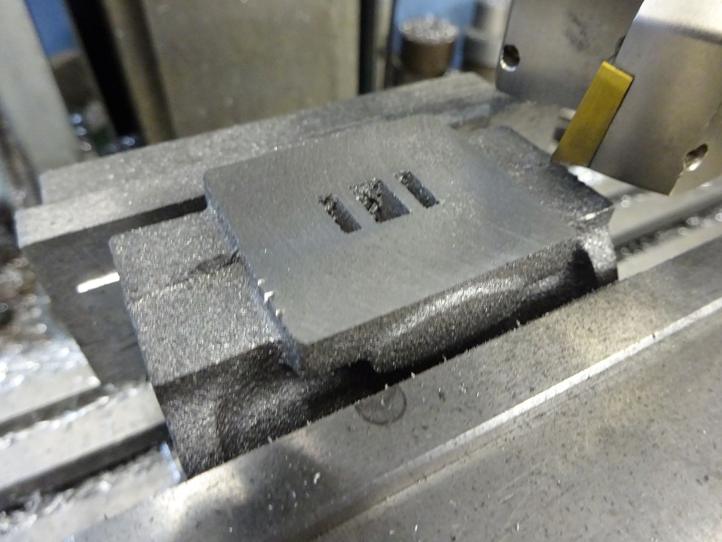
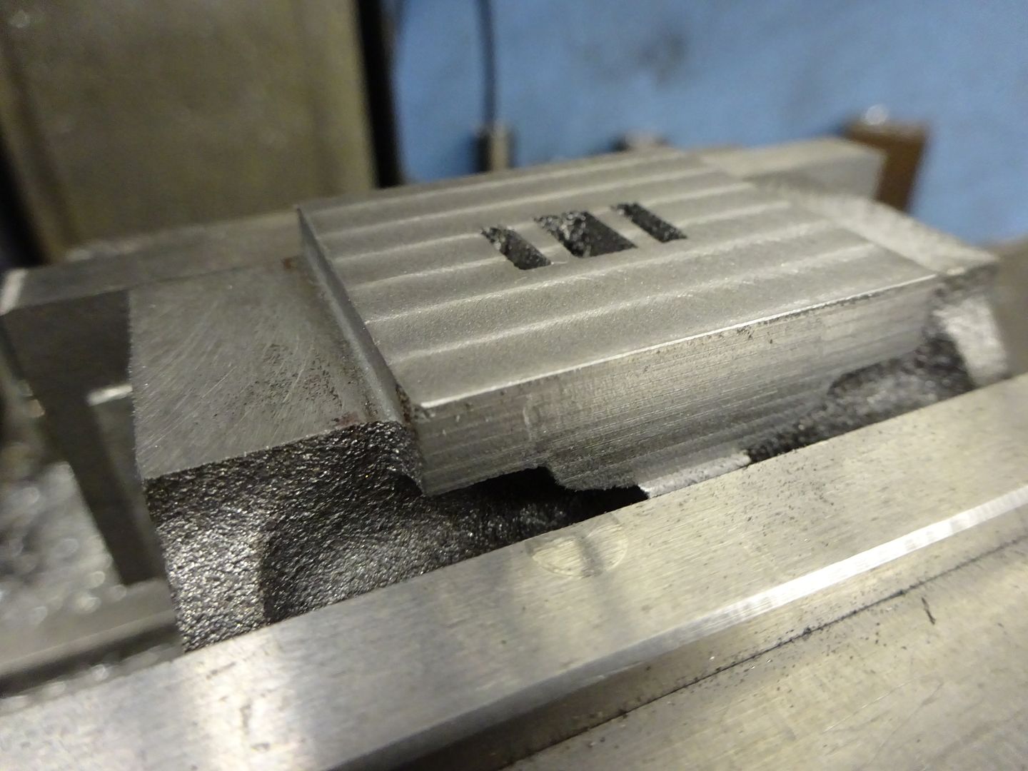
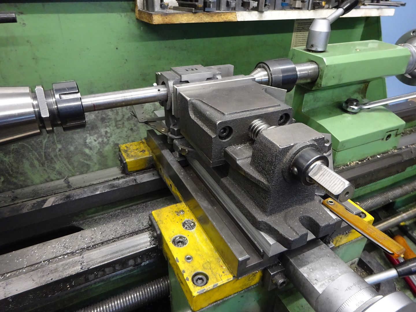
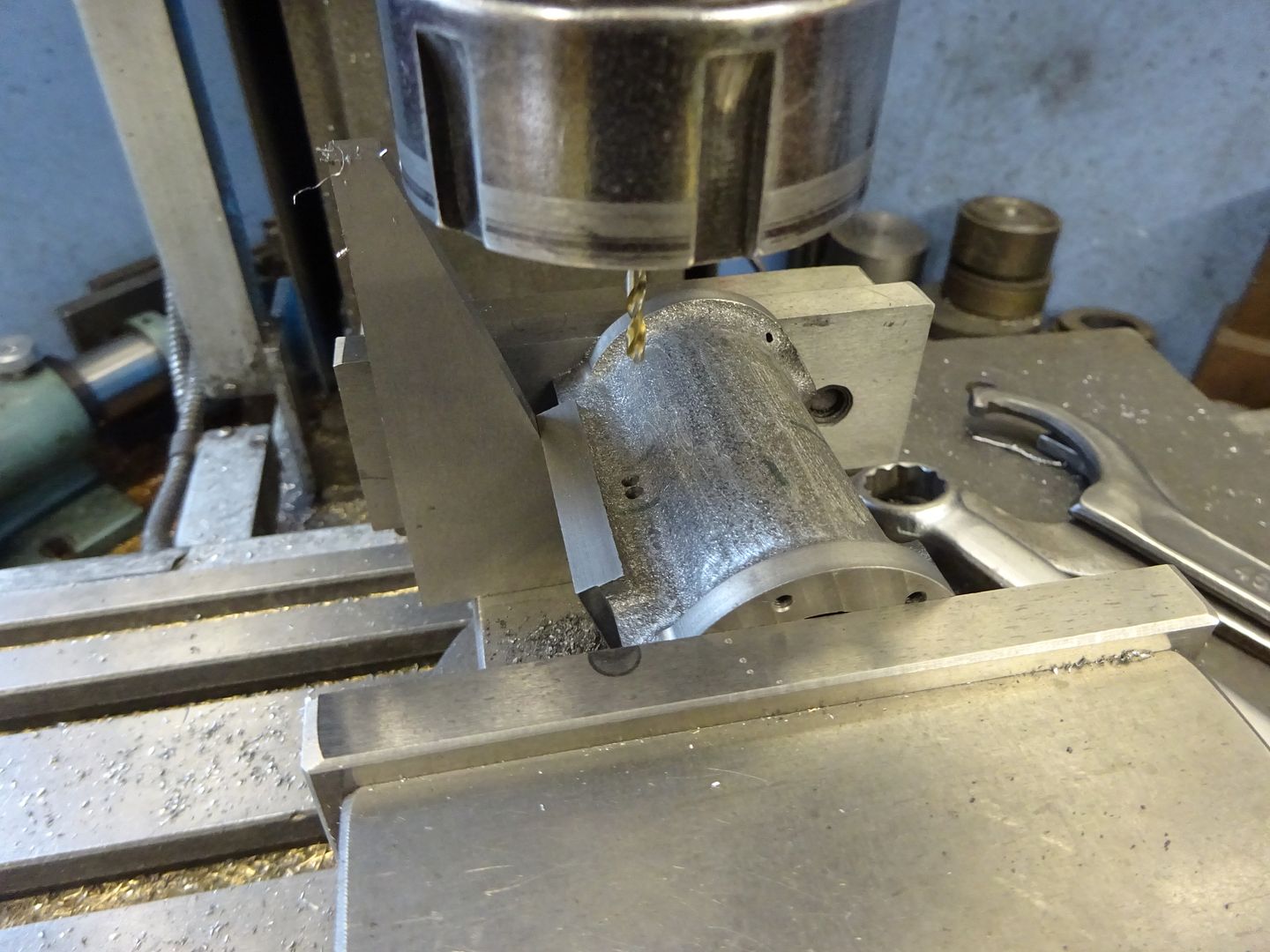
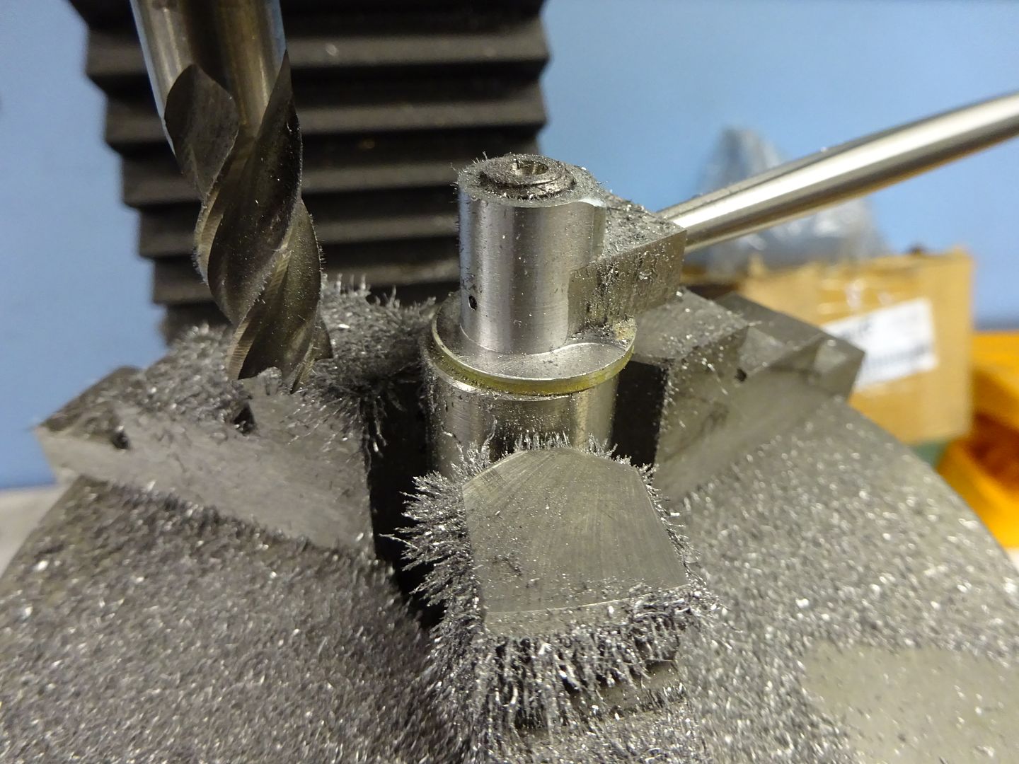
Part way through doing the cylinder I realised that there was a way to machine the portface, bore and one end of the cylinder all in one setting which would ensure all are true to each other so would suggest that the cylinder is mounted in your vice with the port face up and the piston rod end of the cylinder just protruding from the side of the vice jaws not in the middle as the first few of my photos show.
I started by setting up the casting so it was as true as possible in the vice using some thin strips of aluminium between the jaws and casting to take up any irregularities and give a good grip. Not knowing if there may have been some hard spots I took a clean up cut with an insert face cutter.
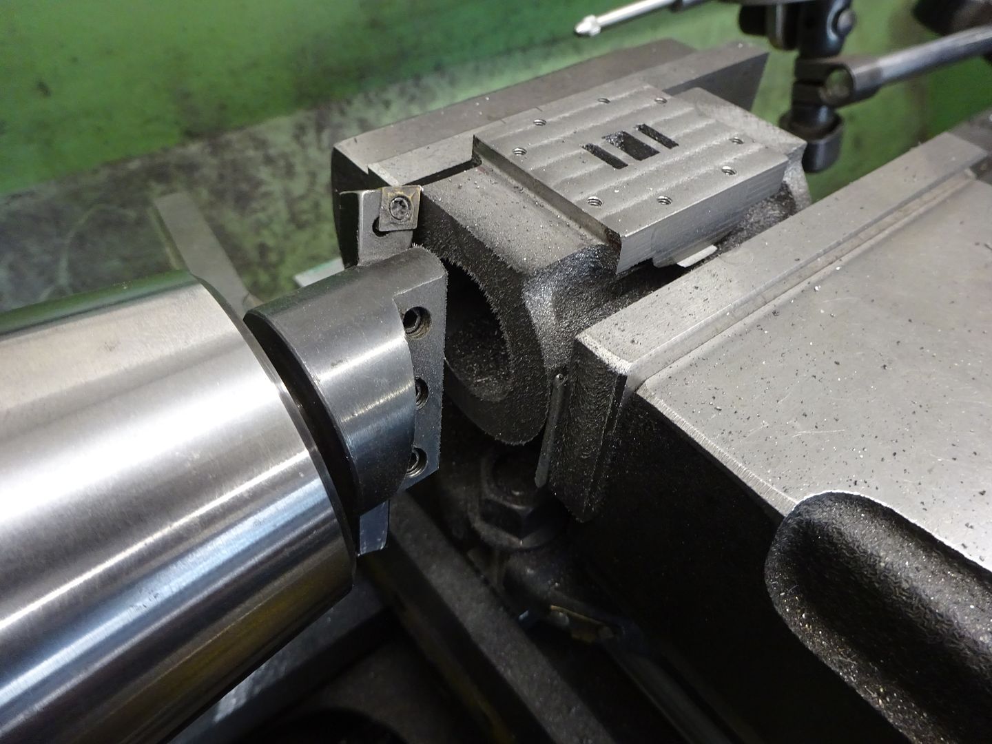
All was well and I also used this cutter to clean up the two flat areas above and below the portface, the 0.8mm radius corner of the inserts leaving a nice internal fillet. Changing to sharp 6mm cutter the portface was machined to finished size, using a small cutter with a 60-70% stepover gives a good flat surface that you may not get with a larger dia cutter if the tram is a bit off.
There was also just room to get the 6mm cutter down the side of the portface to remove the protruding exhaust connection boss as I won't be needing that.
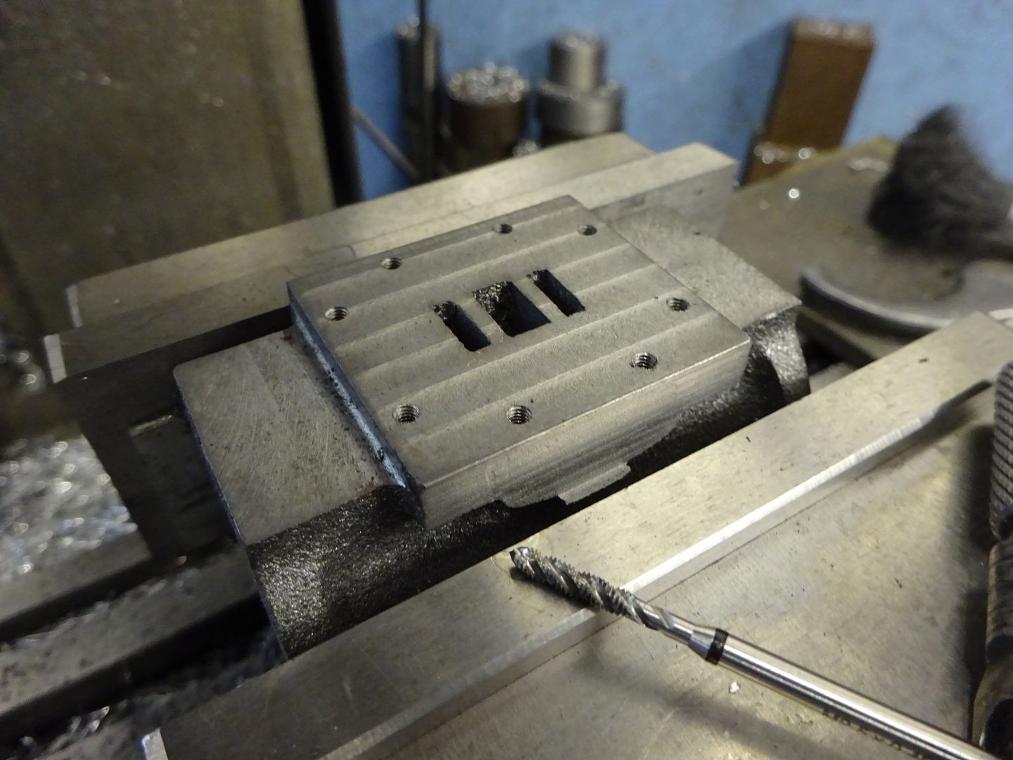
I then drilled and tapped for the valve chest studs. rather than the original six hole pattern I went with an eight hole one as that cleared the side inlet position I wanted to use rather than connecting the pipe to the steam chest cover which is a bit of a pain when it comes to setting the valve position.
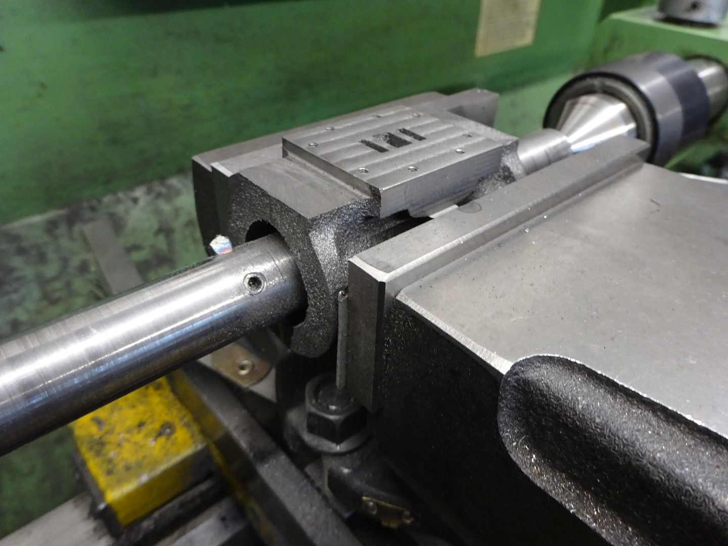
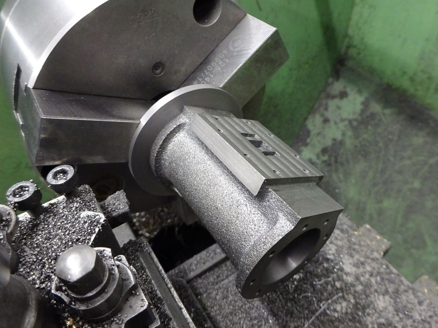
Over to the lathe and with the casting in the vice now shown in the position it would be best to start out with it was just a case of adding some packing under the vice to bring the cylinder ctr line up to that of the lathe and using a between centres boring bar to take the cored hole out to the required 25mm bore.
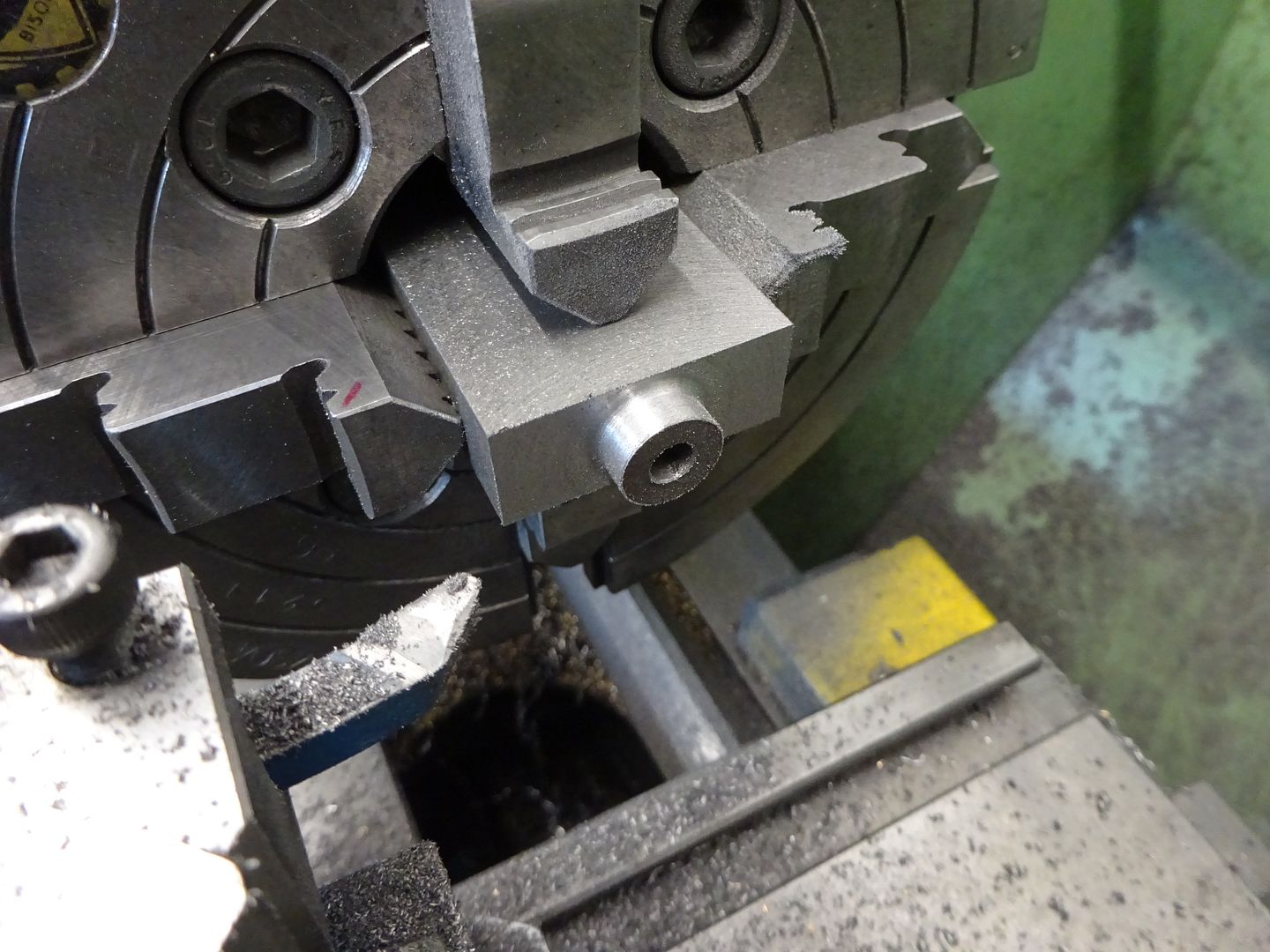
Without disturbing the cylinder in the vice the end of the cylinder that will have the piston rod can now be machined square to the bore by using a flycutter
Back to the mill with the recently flycut end clamped to the mill table the other end can be milled and the cylinder brought to the desired length.
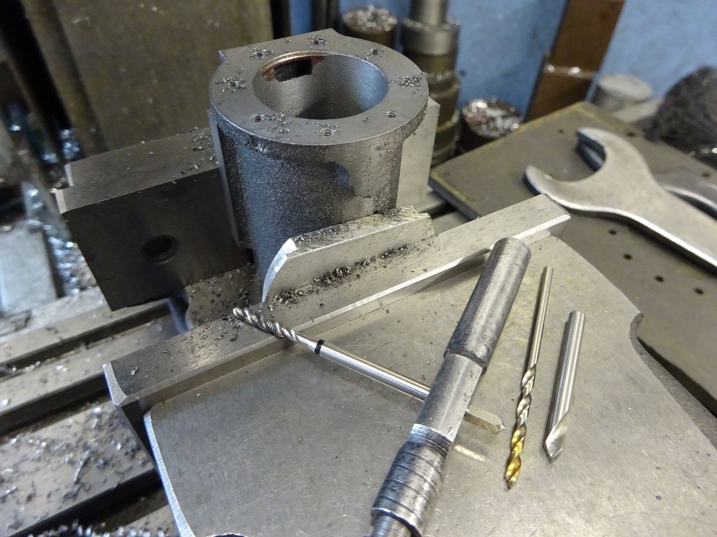
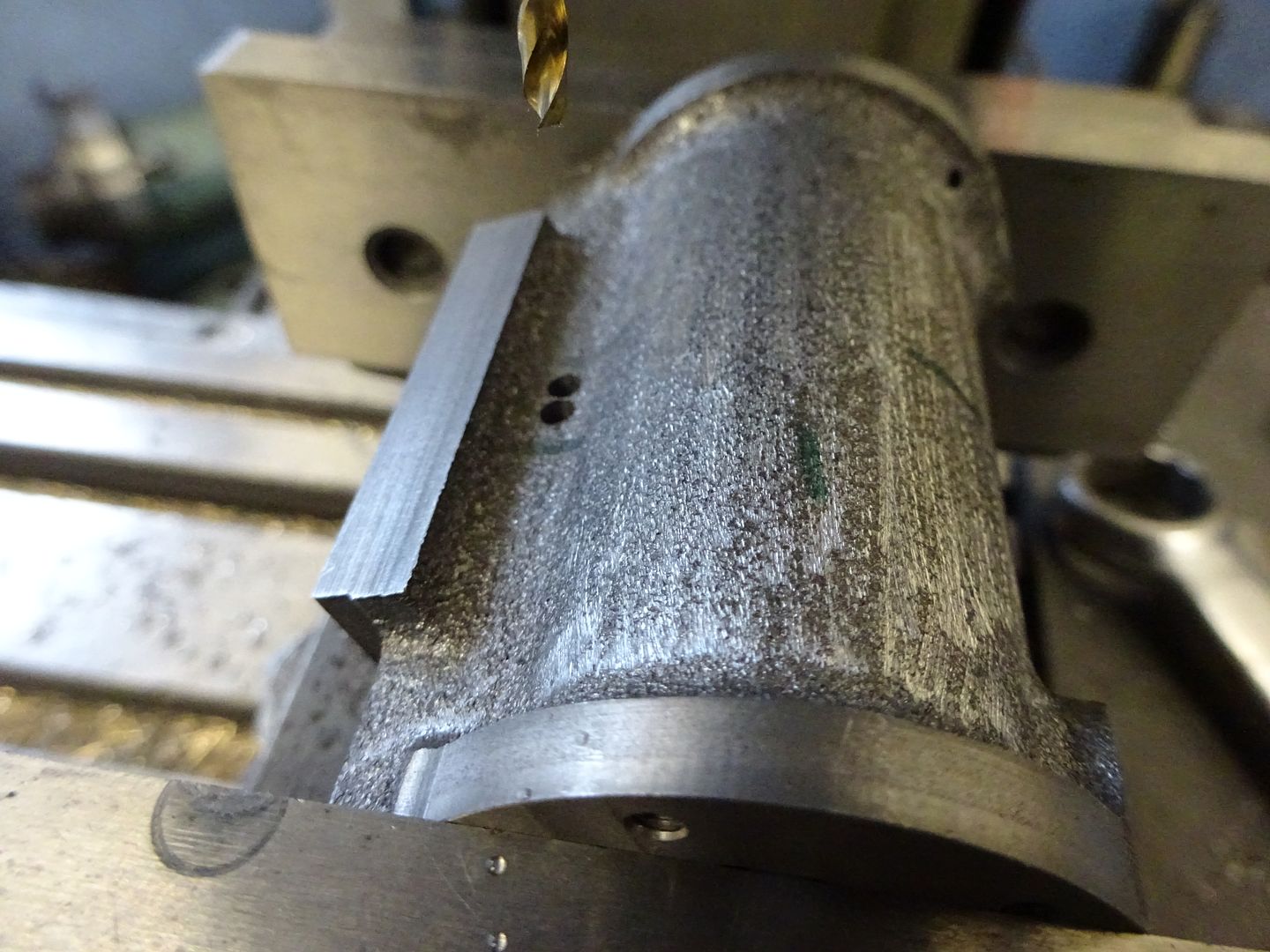
Finally for now with the portface registered against the vice fixed jaw the cylinder ctr can be found and the holes drilled and tapped. I used six M3 holes at the bottom to take M3 CSK socket screws up through the end cover and eight M2.5 at the top for studs and nuts as they show.
I'll cover that exhaust alterations lather in another post.
1 June 2022 at 20:25 #600236 JasonBModerator@jasonb
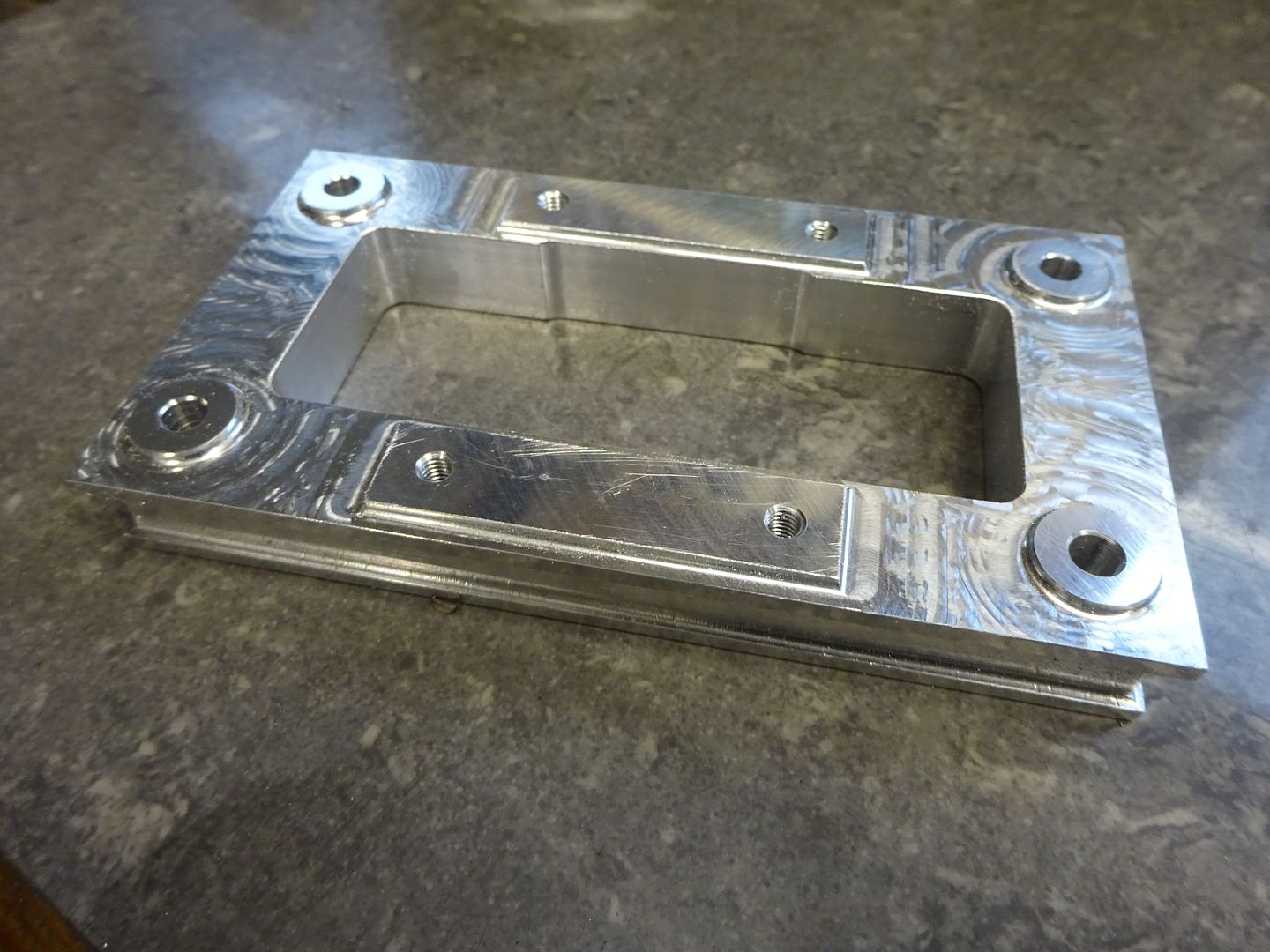
The entablature supplied with the engine is really the" wrong way up" as classic architecture would have the bottom smaller than the top so it flairs out much like the capitals at the top of a column. So a new one was designed to be the right way up and also have a recessed middle band and raised bosses for the bearing supports and column nuts.
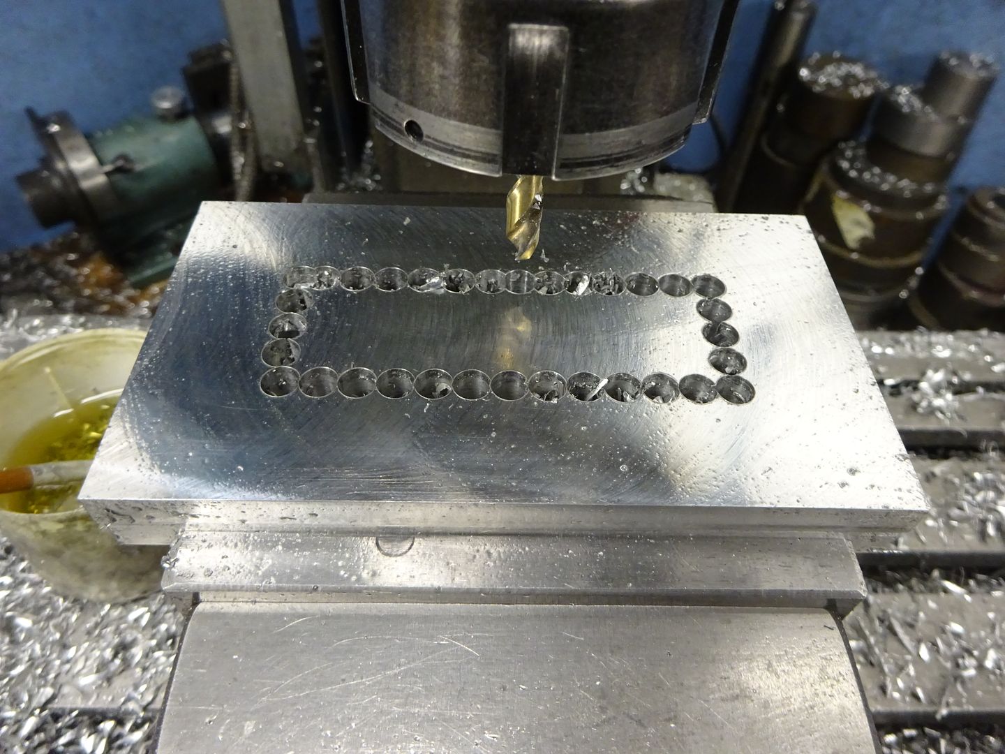
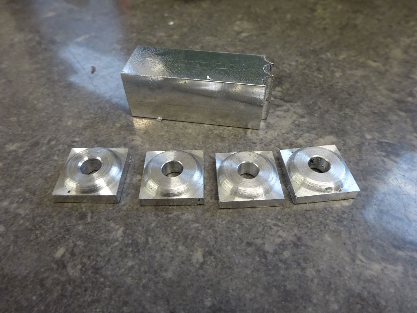
I started by milling down some 5/8" flat bar to 15mm thick with an 80mm insert facemill and then used a 6mm split point stub drill to stitch drill out the waste, These drills don't really need spotting first and being short don't wander into the previous hole. Keep the bit of metal removed from the middle as it will get used later.
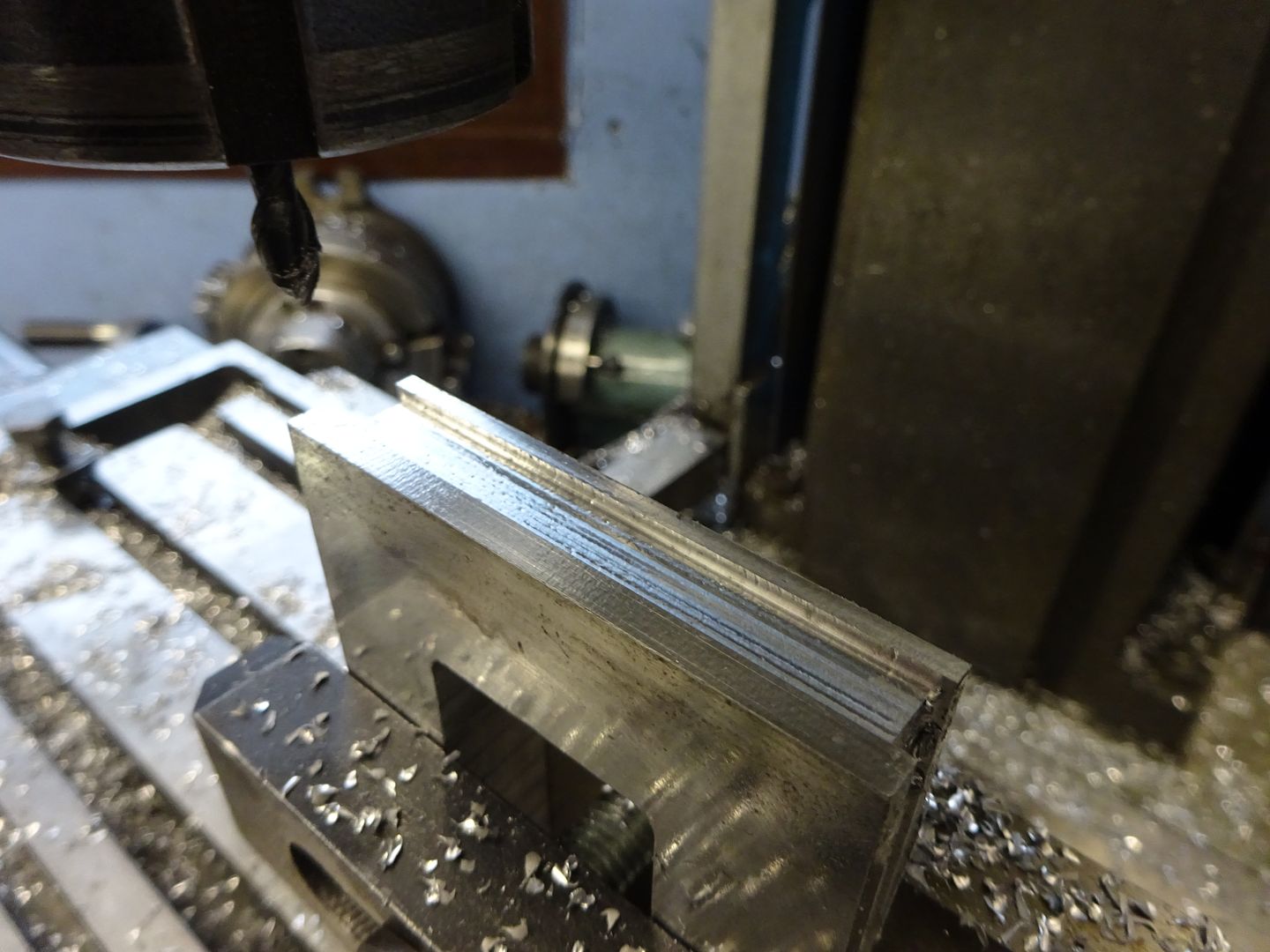
After milling out the rectangle the four sides where milled to profile, for the mid section I used a 6mm cutter with a 1mm convex corner radius which leaves an internal fillet for that cast look.
After that the various holes were drilled and the bosses machined with the same corner radius cutter, I used the CNC but if you were doing similar on a manual machine then I would mill the two rectangular bosses but counterbore for the round ones and loctite in four turned "washers" unless you want to set up for each one on a rotary table. You can also see on the far side of the cut out that there is a deeper section which gives additional clearance to the eccentric allowing it to sit closer to the valve chest helping to do away with the cranked valve rod of the original design.
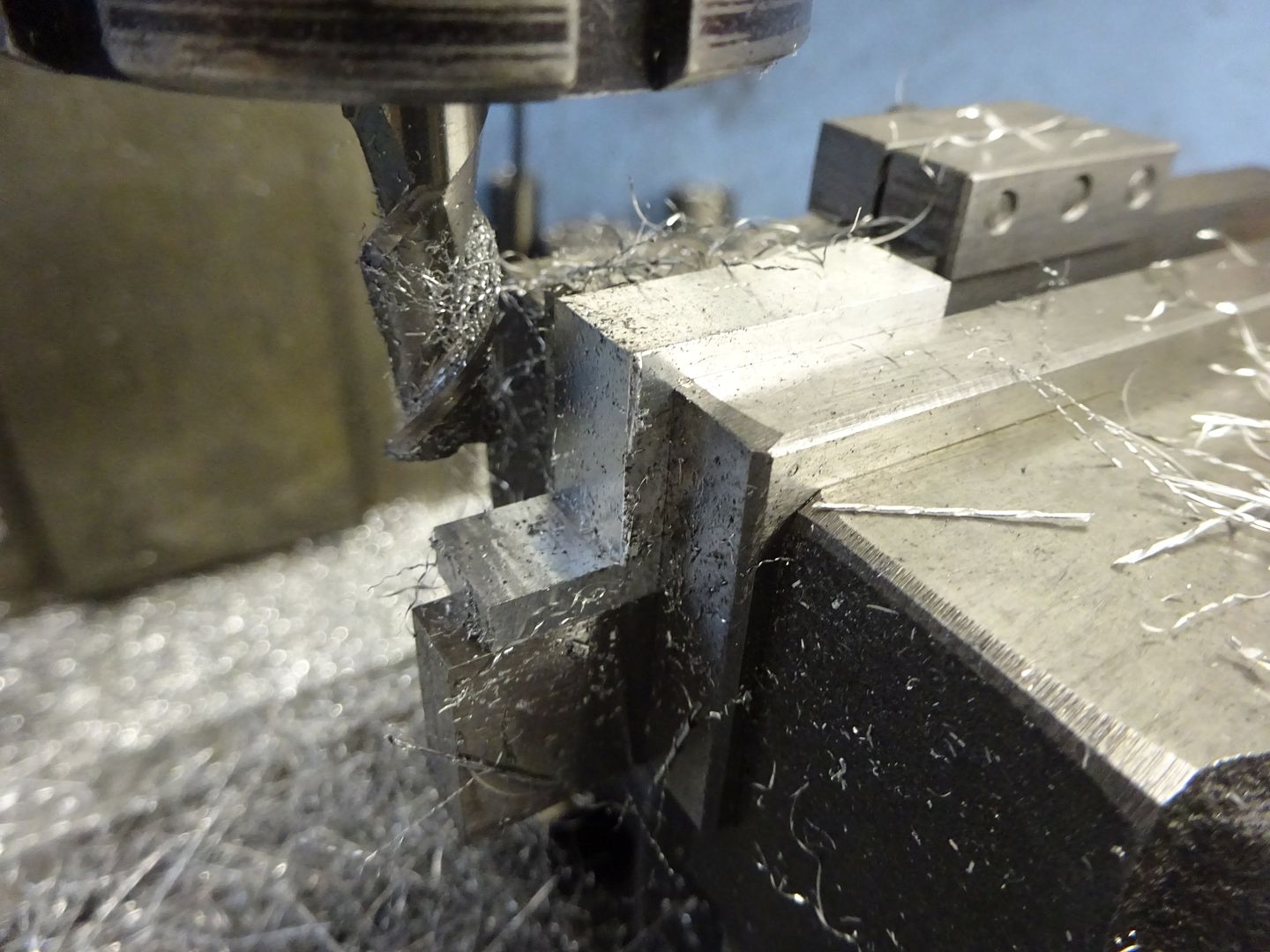
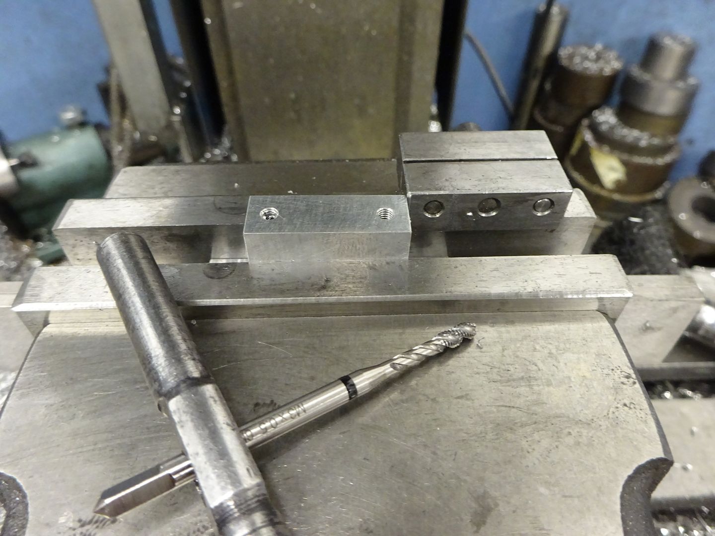
The bearing supports start out as rectangles of aluminium from the same piece that the base was cut from, Milled at each side to leave the feet and then drilled and tapped for the bearing caps
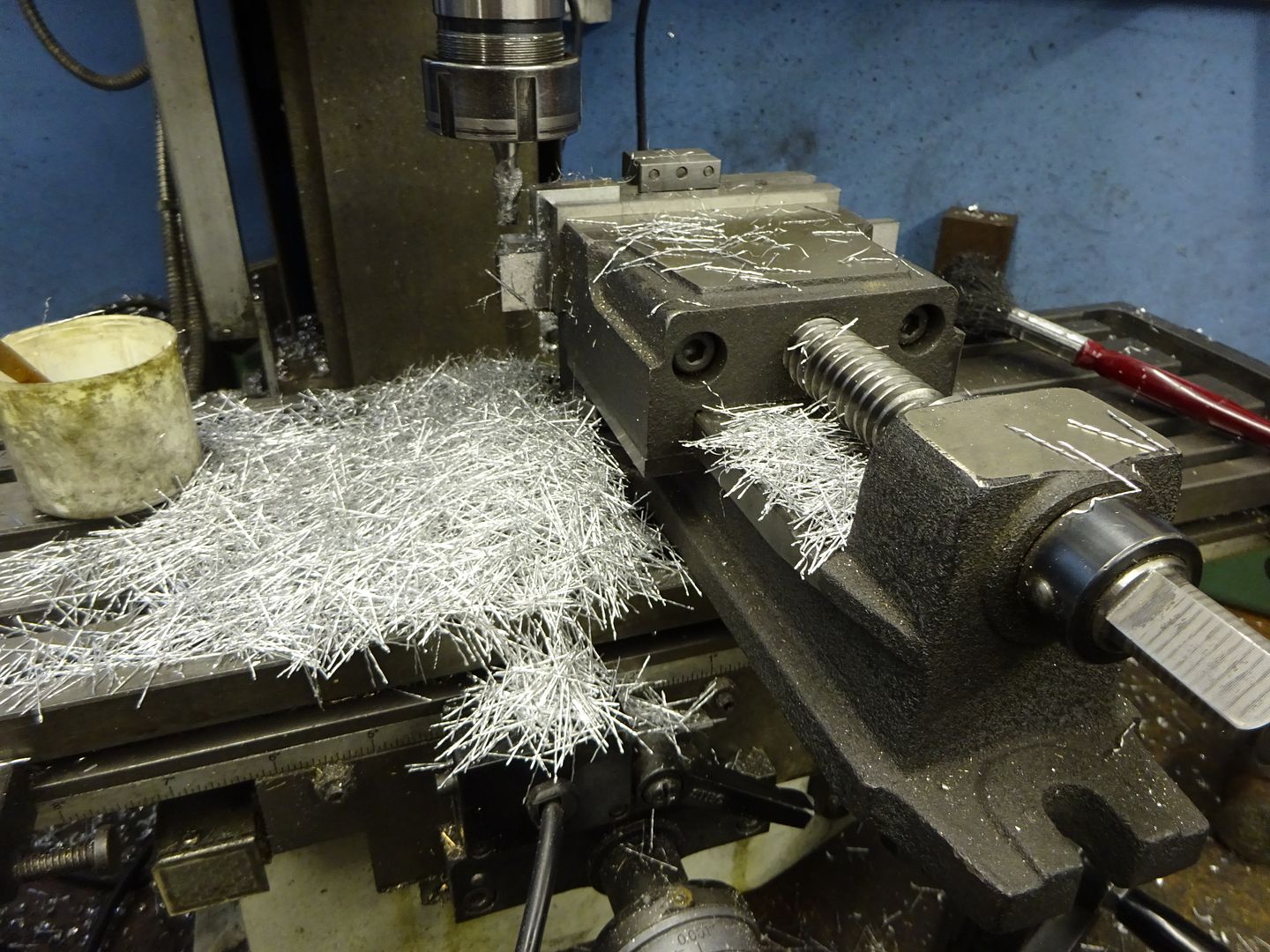
A two flute carbide cutter specifically for aluminium makes quick work of this taking full depth passes of 1.5mm wide per pass.
A simple vice stop allows the two parts to be swapped over in the vice without the need to keep locating their position and a spiral flute tap removes the swarf from the blind taped holes
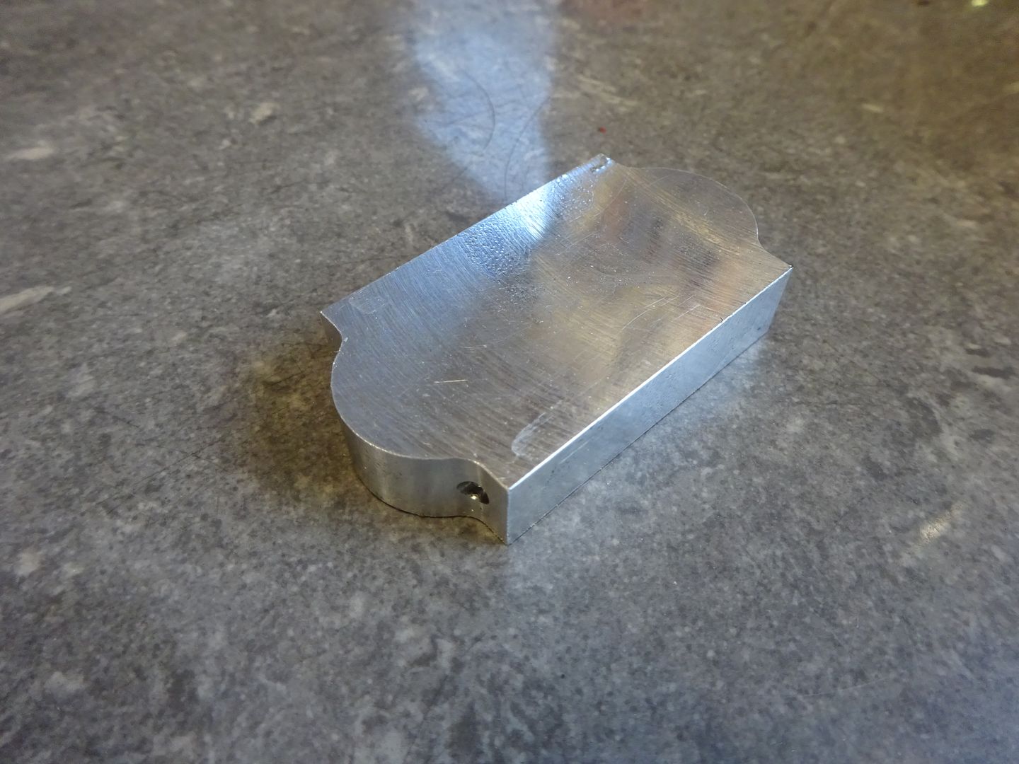
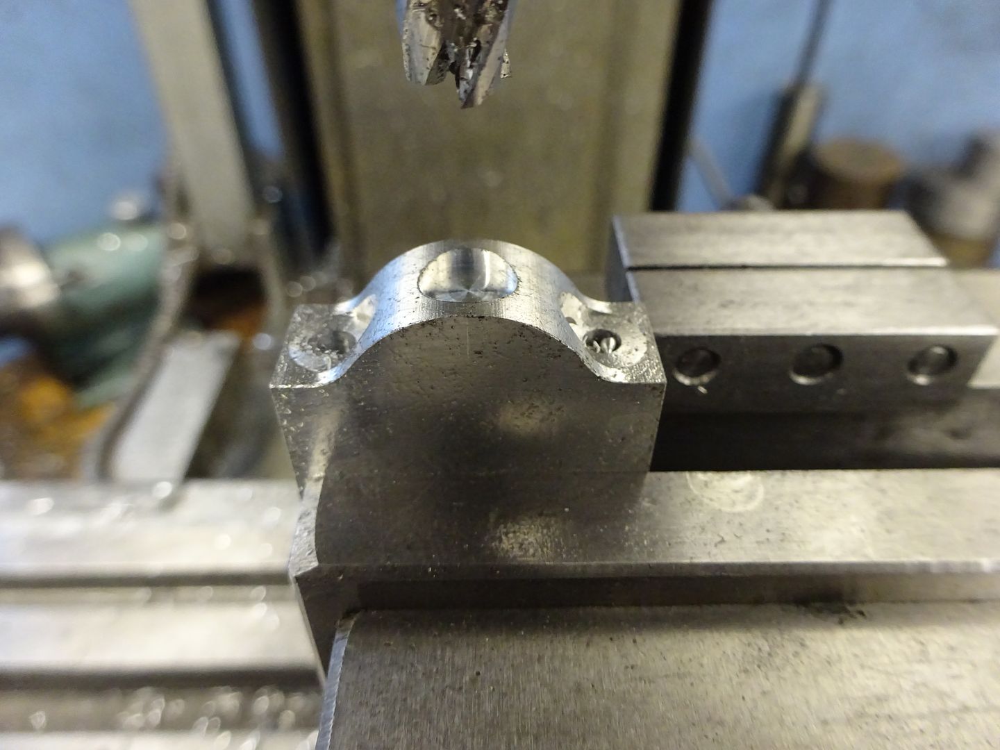
To make it easier to hold the bearing caps while they were machined I cut them on each end of a larger piece of material before cutting them off and cleaning up the cut with a quick skim of a facemill.
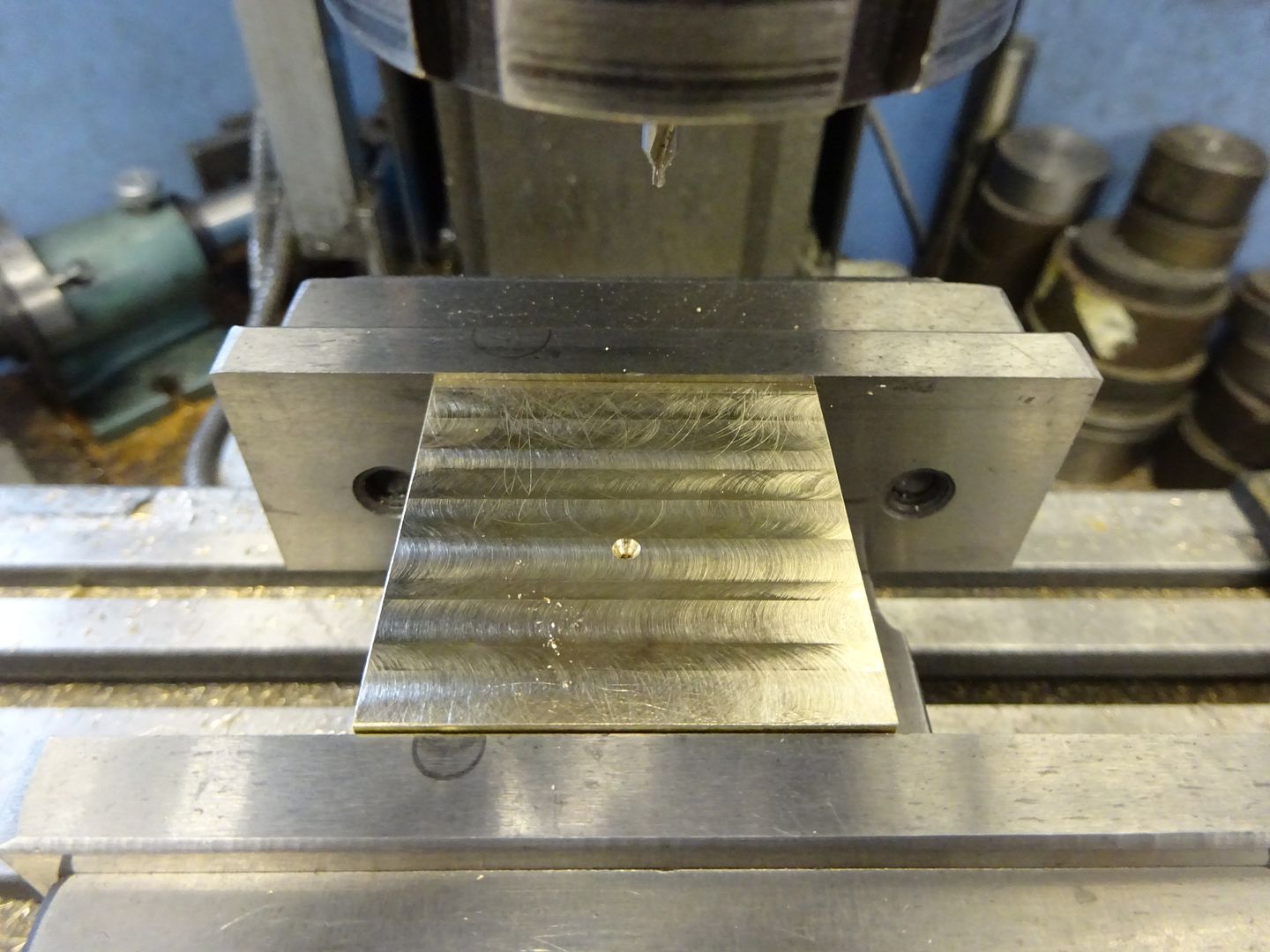
Before cutting off I spot faced for the fixings and also milled a shallow counterbore which will have a short length of rod loctited in that has been threaded M4x 0.5 metric fine for an oil cup.
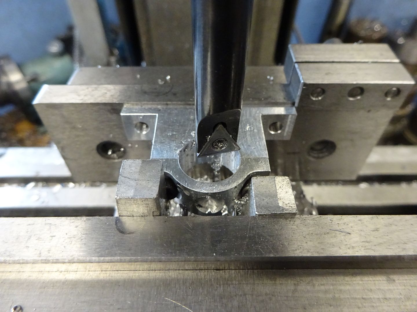
I tend to use cap head screws during construction as they are quick and easy to screw in and undo multiple time s with a suitable ball ended driver. Here you can see them being used to hold the cap to the support while the bearing hole is bored. I have packing on each screw head so that the pressure is not on the crown of the cap which may distort it.
2 June 2022 at 18:58 #600329 JasonBModerator@jasonb
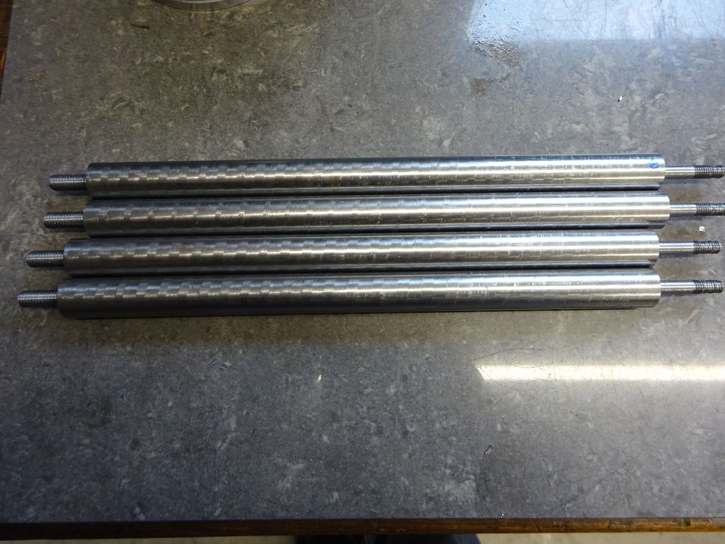
The columns on the engine are quite a noticeable feature, the book just shows them parallel turned to 1/2" diameter from 5/8" stock leaving a small flange at each end and a not "embellish as desired" which I decided to take them up on
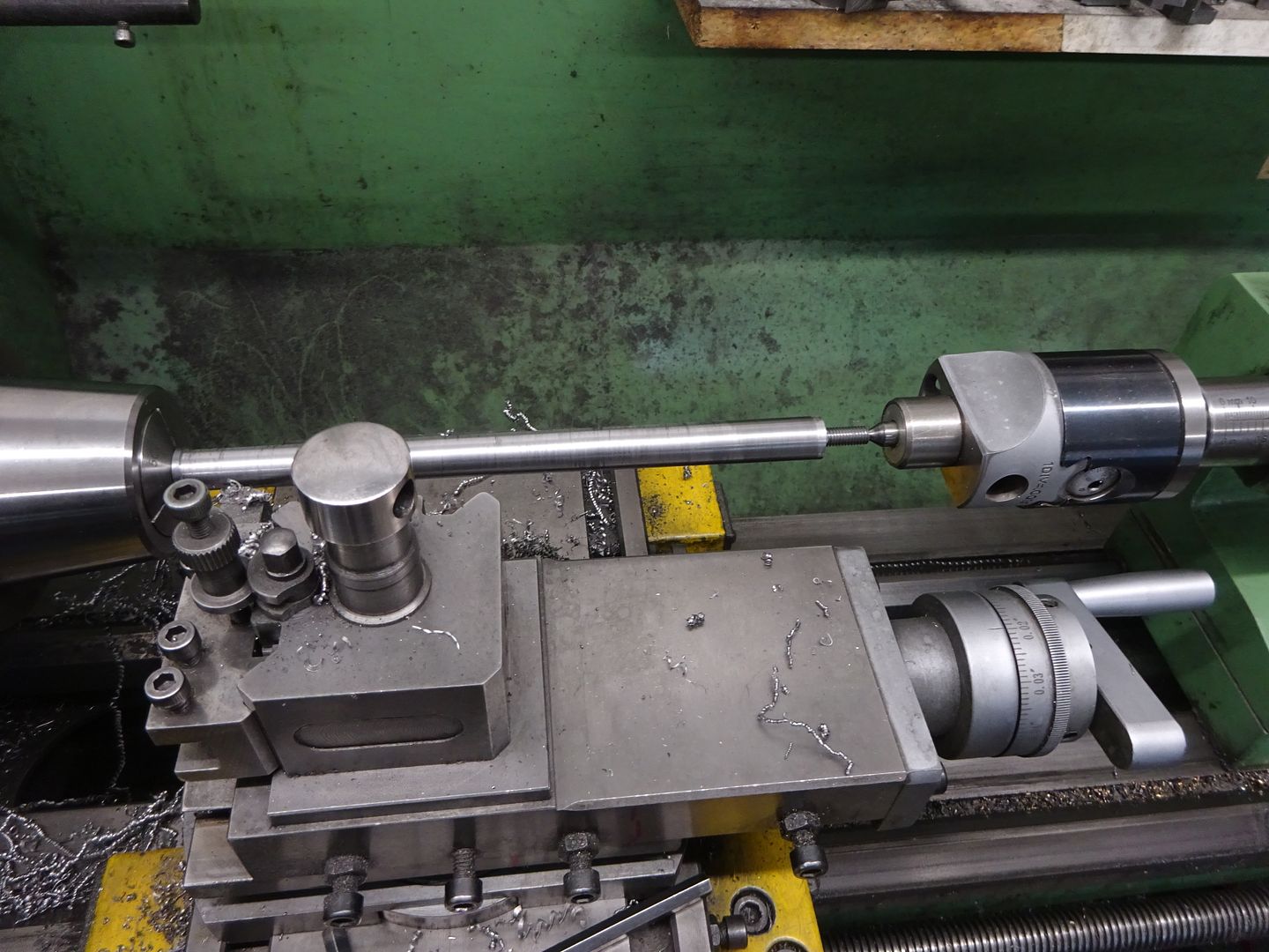
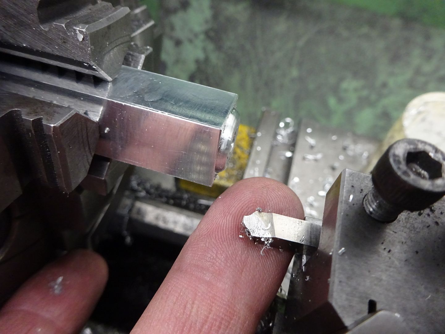
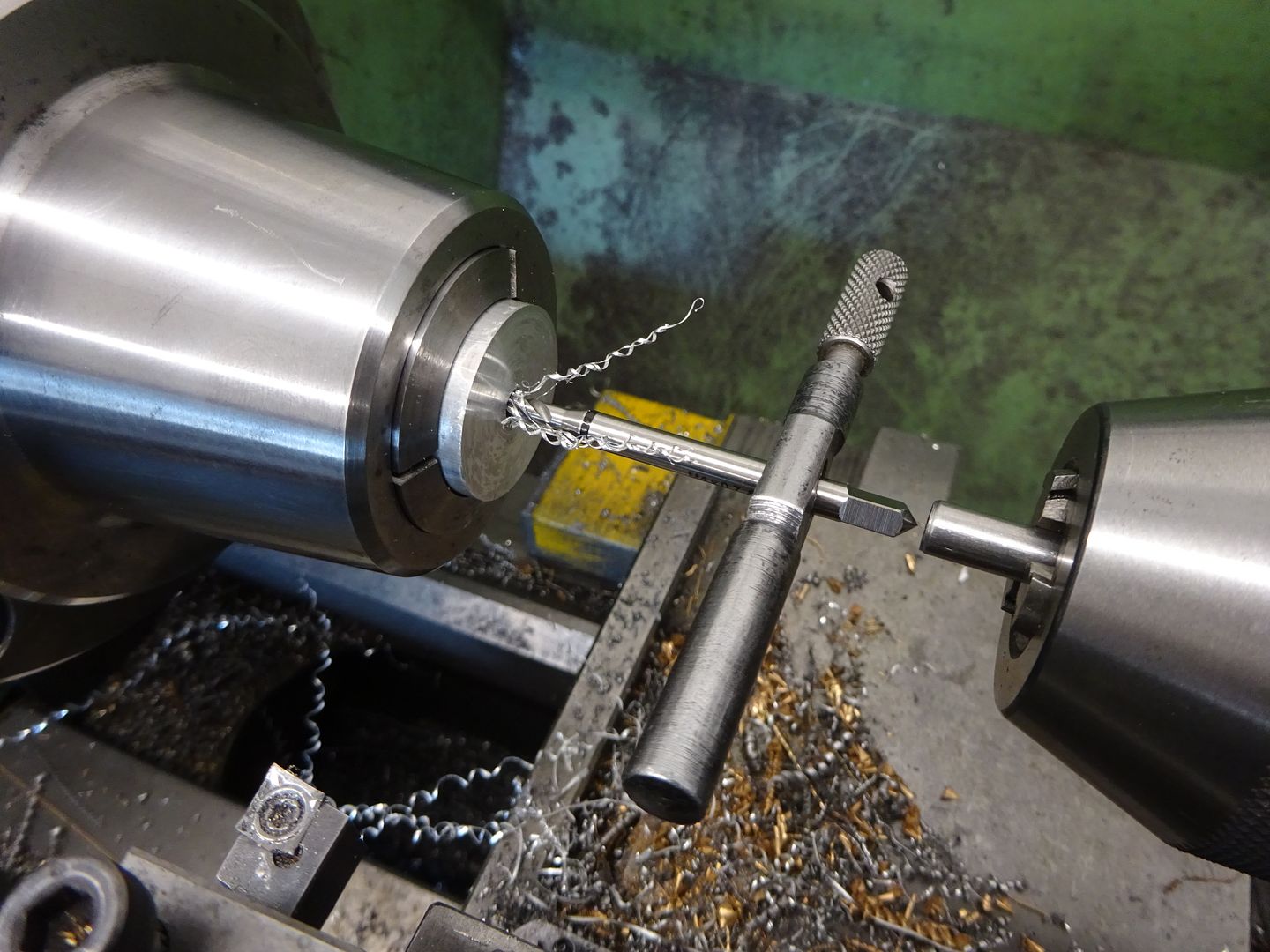
I started out with some 14mm rod, this was ordered as EN1A but was really nasty to machine and also had quite a pronounced spiral finish on the outside. If you look closely at the threads on the right they were tearing and I was not hopeful of getting a good finish on the long slender taper.
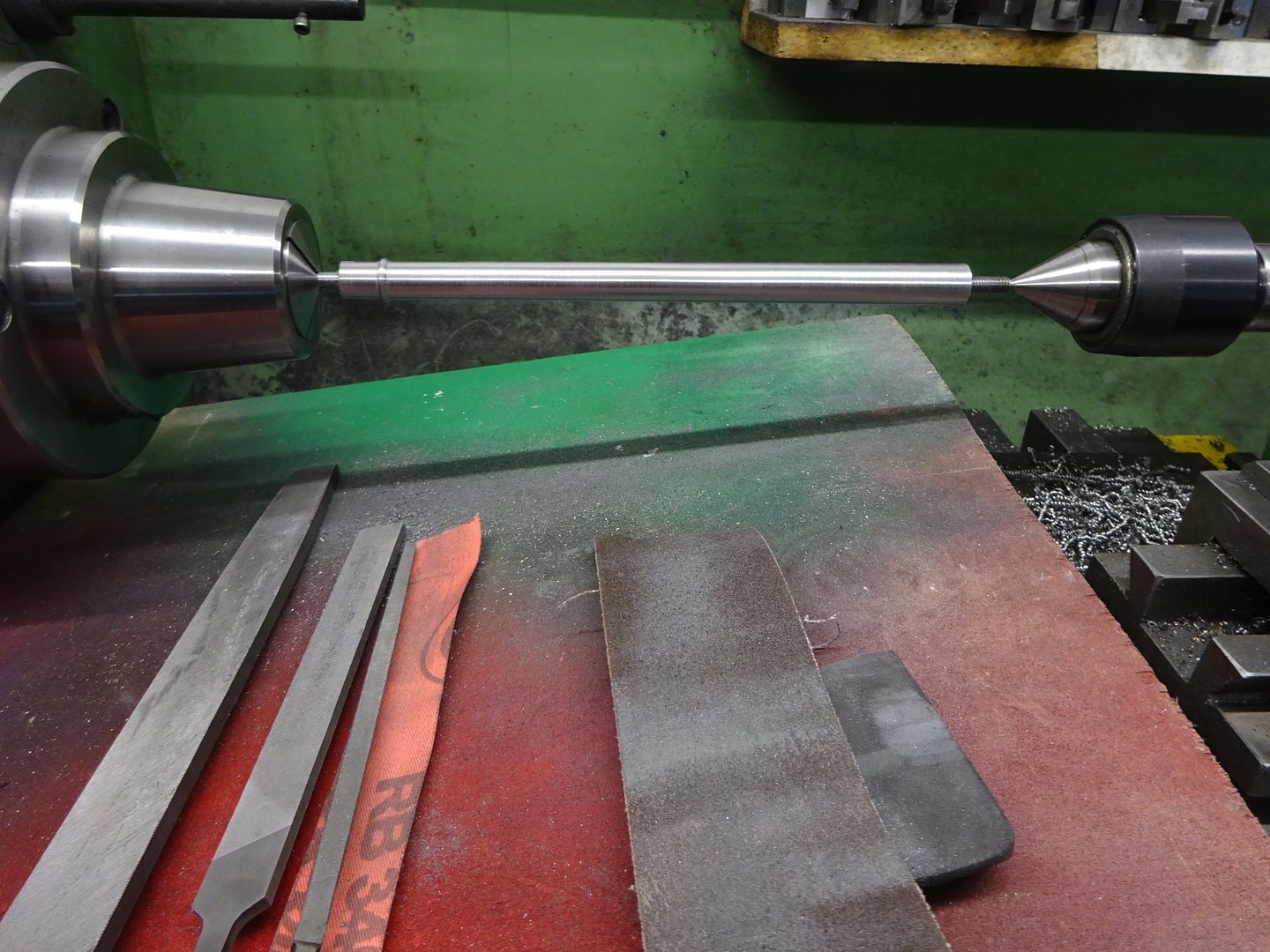
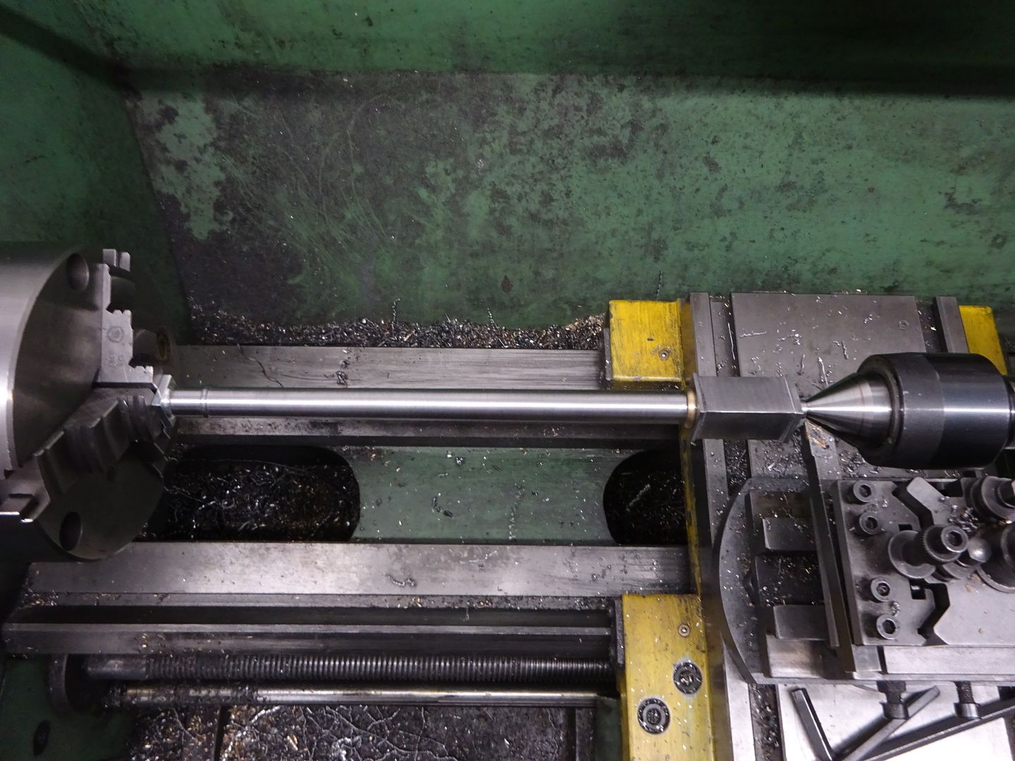
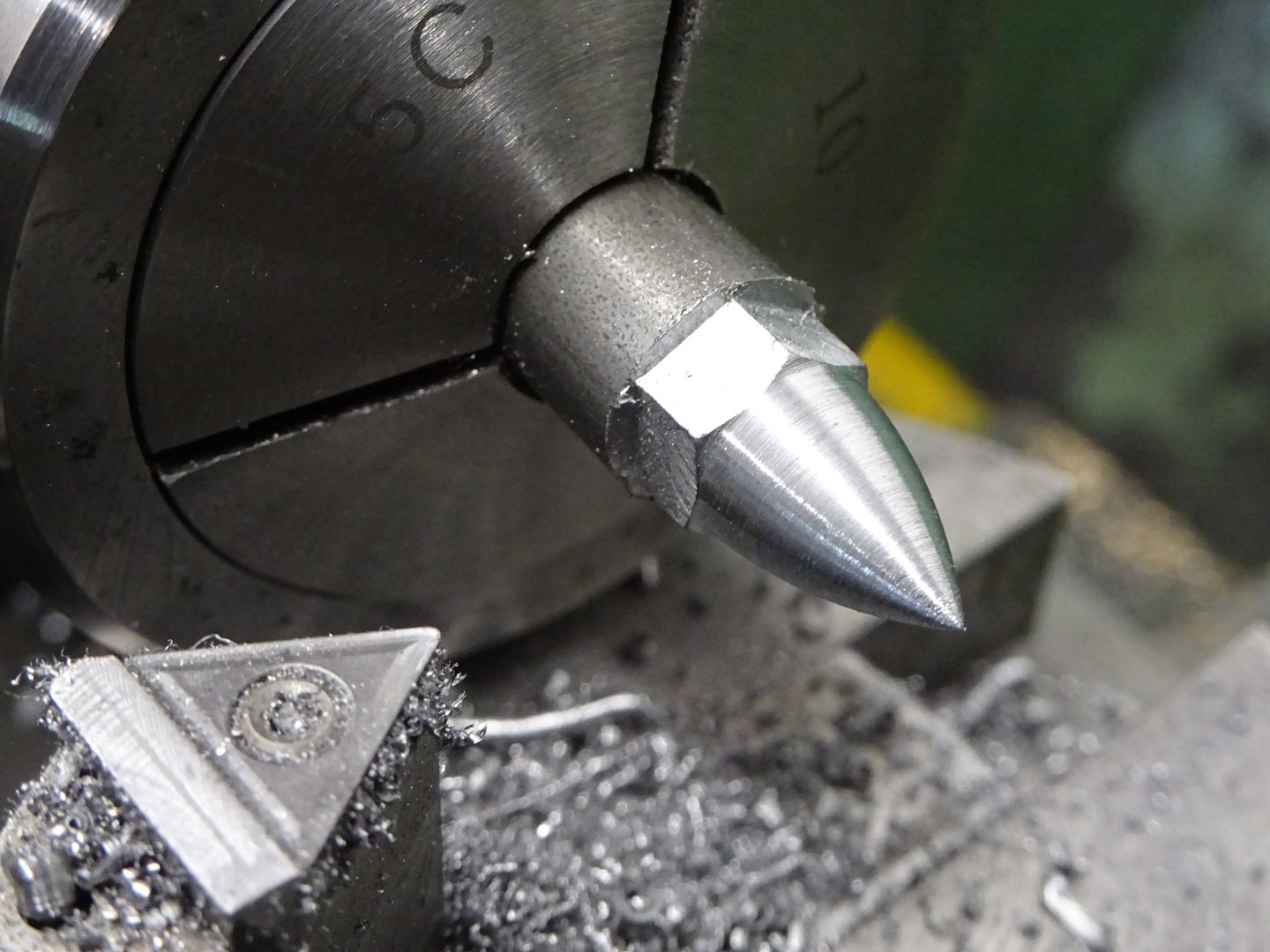
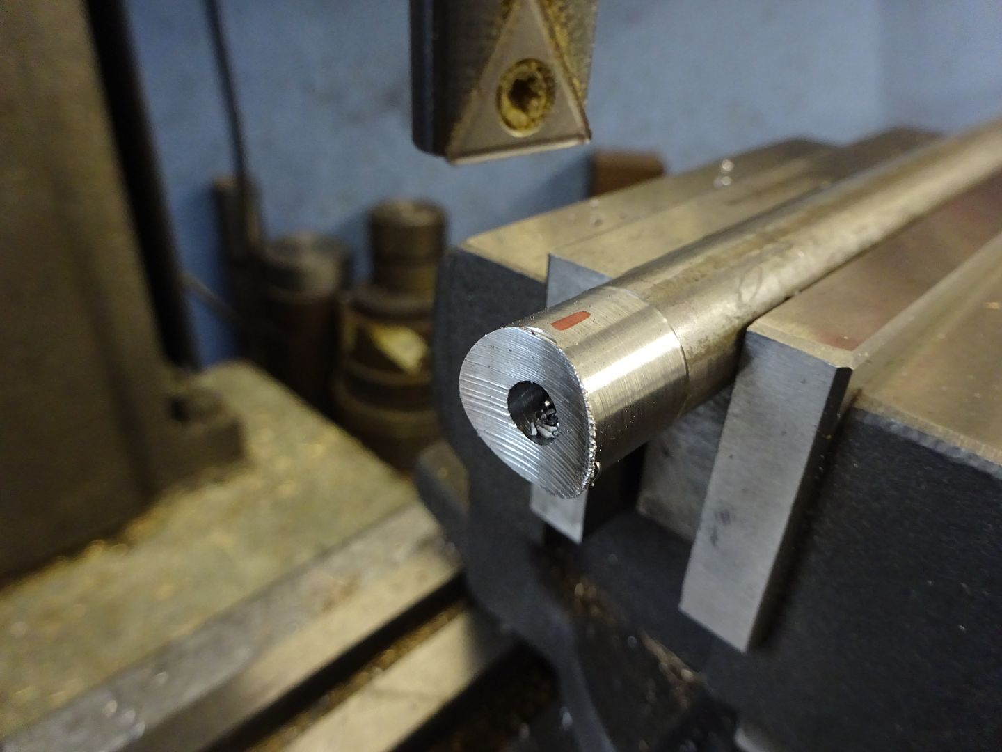
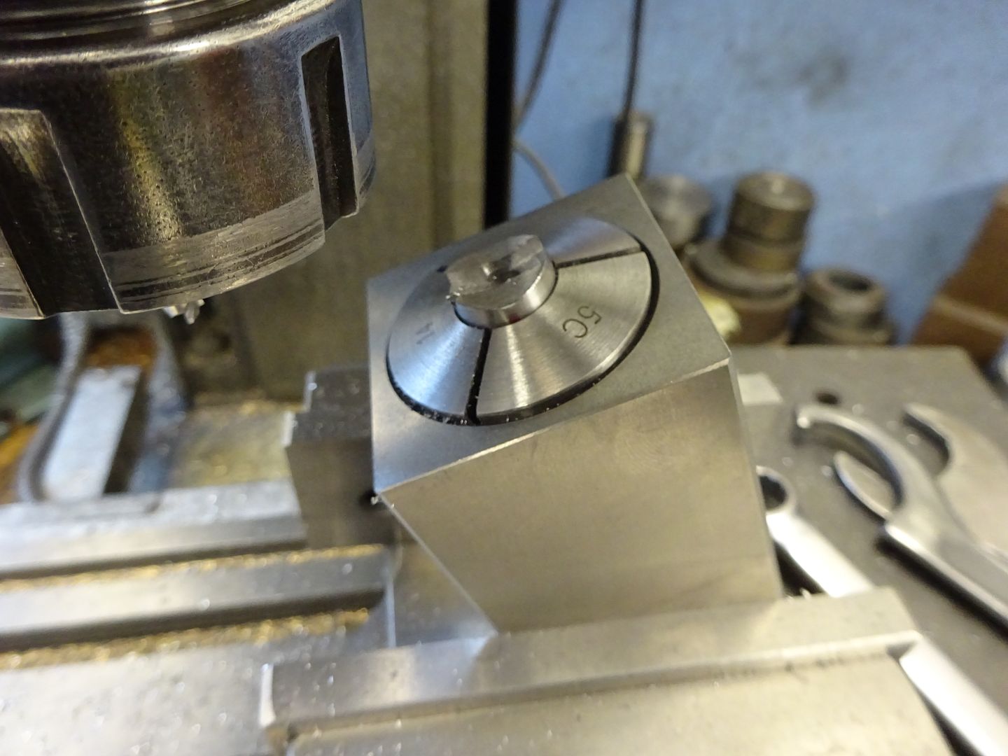
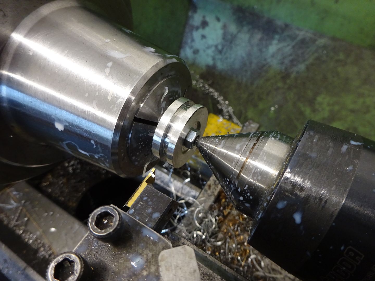
After reducing the top 10mm length to 11mm diameter I then changed setup gripping this short length in the 5C chuck and supporting the other end with a small rotating ctr held in my Boring head which was offset to allow the taper to be cut. Initial cuts were not good but after trying a few different inserts I settled on a CCGT insert with 0.8mm tip radius which seemed to give a reasonable finish.
Then driving by holding the top spigot I just hand filed the rectangular ring that I had left into a half round profile and also gave the columns a quick going over with Emery cloth to clean up the finish good enough for painting.
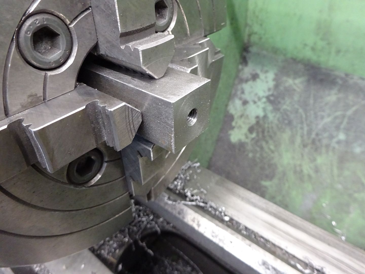
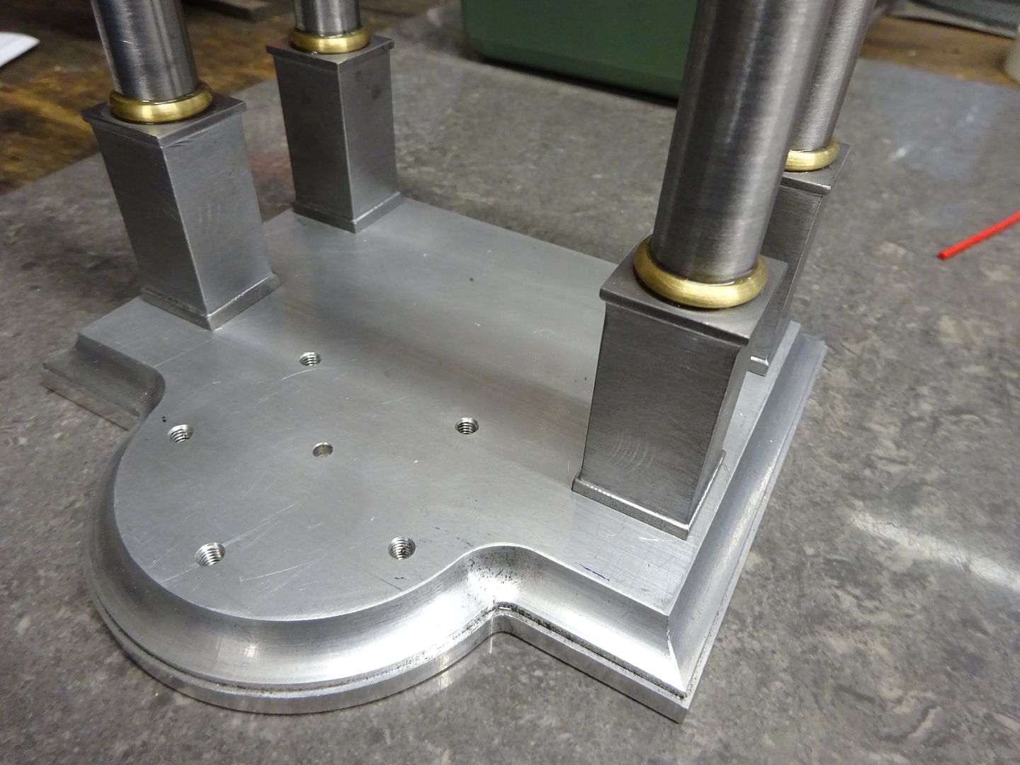
I cut off 4 pieces of 20mm square steel, faced one end and tapped it to suit the turned part of the column then the other end had a spigot turned to closely fit the counterbores in the base before drilling and tapping M5. After this I milled 1mm off each side leaving 3mm at the bottom and 2mm at the top the full 20mm size. This was done with an insert endmill with 0.8mm corner radius tips which once again left an internal fillet for that cast look.
The piece of aluminium that I stitch drilled out of the entablature was milled down to 15mm square and the capitals machined from that using a form tool before parting one of and then repeating for all four.
Most columns of this style also have a half round section between the square base and tapered column so some thick "washers" were parted off and then screwed onto a mandrel for profiling.
It was now just a case of assembling the various parts with soem Araldite expoy adhesive and setting aside for 24hrs to cure. After the top spigot was held in teh 3-jaw with the capitol hard up against the jaws which acted as a stop. It was then just a case of locking teh carriage and facing each end to final size which ensured all would be the same length.
Close up of the bottom
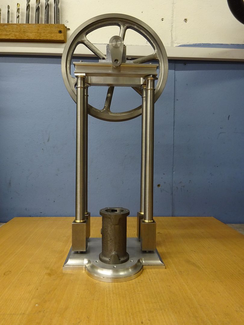
And progress so far at which point I started to think that it could possible take a larger diameter flywheel
 4 June 2022 at 18:09 #600586
 JasonBModerator@jasonb
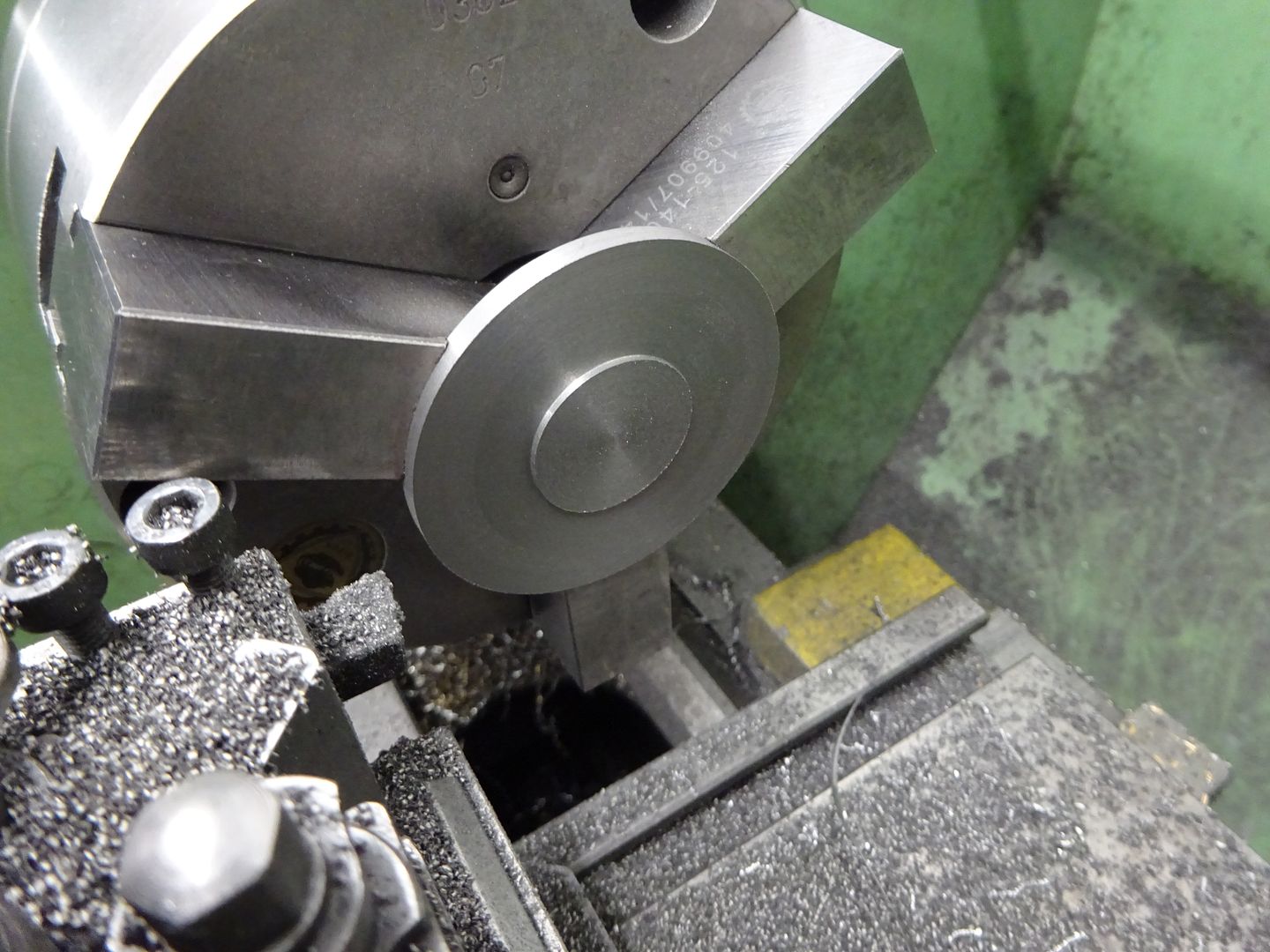
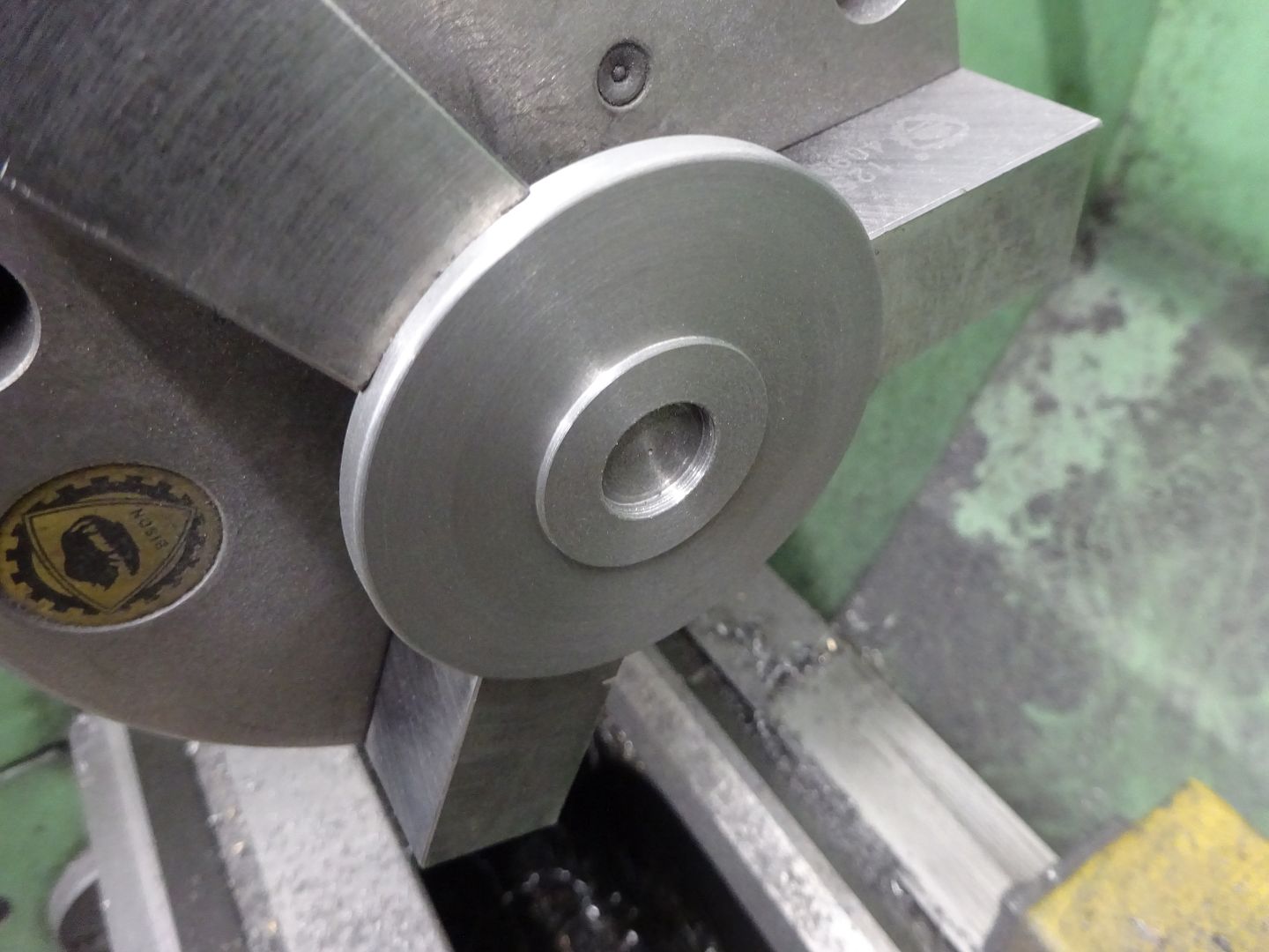
Stuarts use a square cylinder end cover to mount it to the base but as mine has the rounded projection that really needs a round cover to match. So a slice was sawn of some 60mm CI bar, faced and the OD turned. I then flipped it round in the soft jaws to face down to finished thickness and turn the locating spigot for the cylinder
Once again I used the mating part to gauge the fit of the spigot into the cylinder
The only remaining turning was to bore a shallow recess to give some clearance for the piston lock nut.
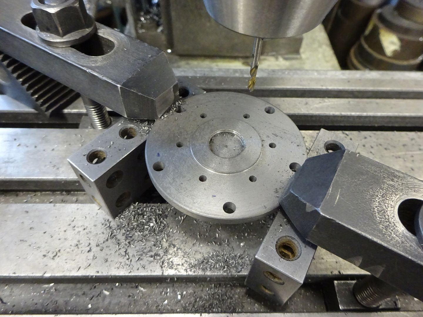
Then over to the mill, the clamps are set at approx 45deg so I can use an edge finder to locate X and Y then the drilling can commence, The six 2.5mm holes were later csk on the underside for socket head CSK screws. The five 4mm holes are for studs to hold the cover to the base. They are not equally spaced, the ones at 4 and 8 o'clock are a little more forward as I was toying with the idea of adding drain cock bosses to the side of the cylinder but decided not to in the end as I don't really need them with air but the thought is there if anyone wants to try these modifications and run on steam. I went with 4mm as the Stuart specified 2BA (4.7mm)looks a bit bulky particularly with their full size hex heads, my nuts will be 5.5mm A/F
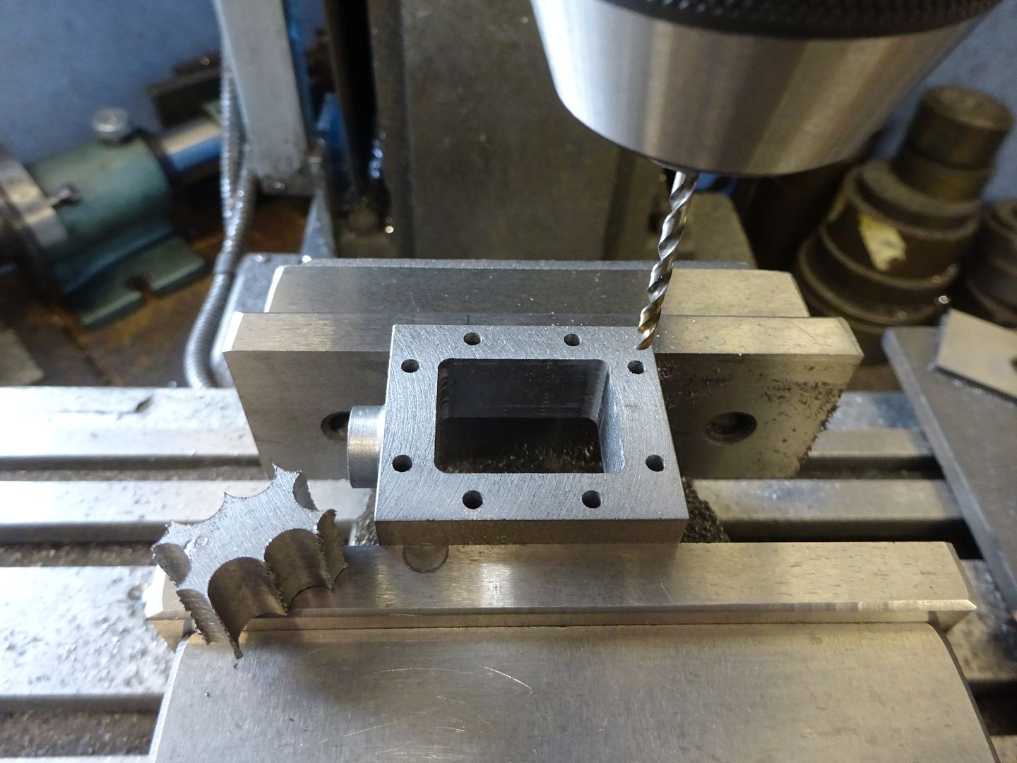
Two slices from the same 60mm cast iron bar can be cut and machined to the overall sizes of the valve chest and it's cover. Then a spigot turned on the end of the valve chest with a round nosed tool before drilling and reaming for the valve rod. I'm not keen on having to drill a guide hole for the rod at the opposite end of the valve chest so once again deviated from the Stuart design and I will use a separate external guide similar to that found on their No1. I opted for round glands to keep the round theme going but oval ones are not too hard to do on the rotary table of you prefer.
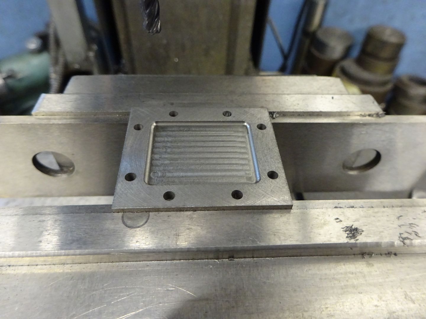
The middle was then stitch drilled out before cleaning up with a 3mm milling cutter then the revised eight hole pattern for the studs drilled, this pattern will allow me to bring the steam/air in through the side of the chest without clashing with a central stud and does away with Stuarts method of attaching the steam supply to the valve chest cover which can be a pain when you want to adjust the valve as you have to strip out the pipework each time.
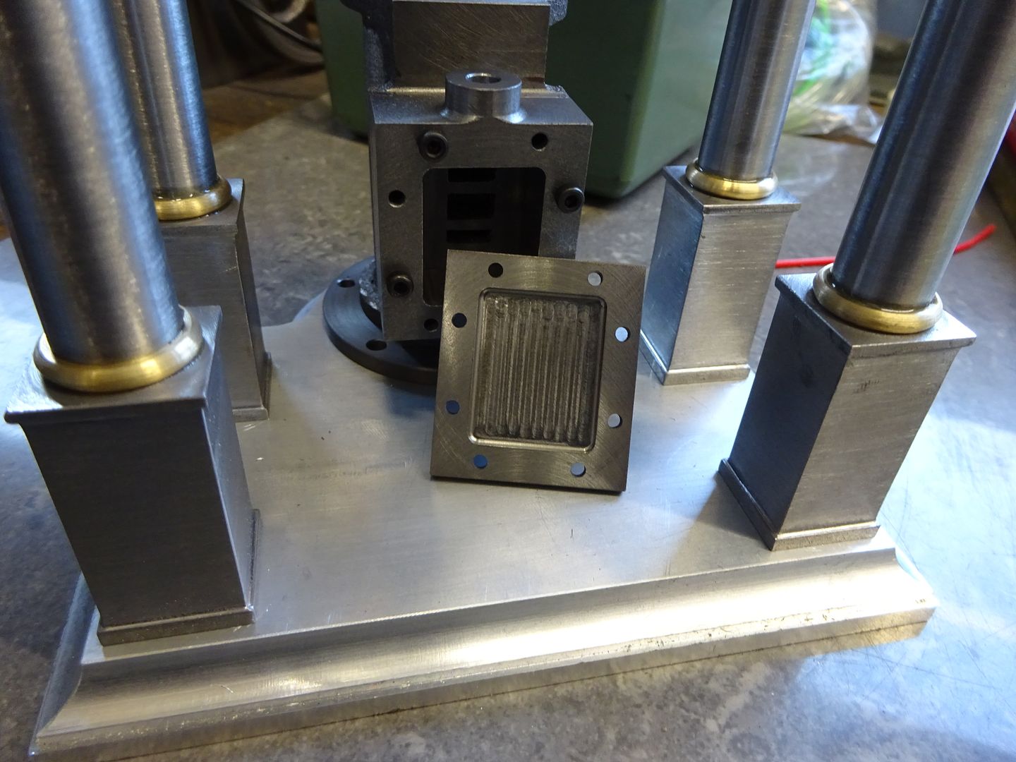
The chest cover was drilled straight after and then a decorative recess milled with a 4mm dia x 1mm corner radius cutter
9 June 2022 at 20:21 #601158 JasonBModerator@jasonb
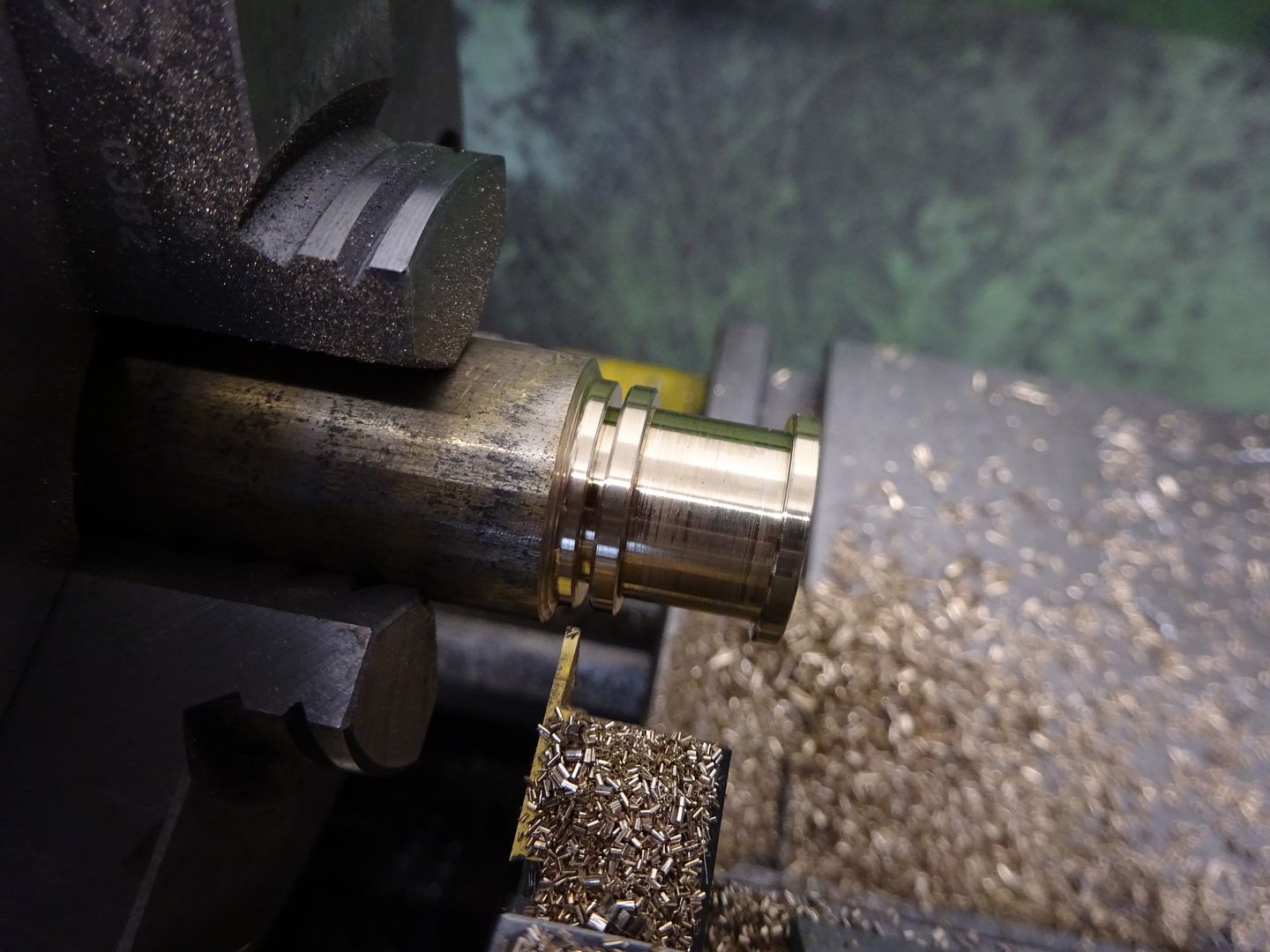
As i doubt my engine will ever do enough hours to need the bearings adjusting I did not bother to make them split, instead I just turned them from bar. The inside was bored to get the fit I wanted on the crankshaft and the waist in the middle to fit the bearing supports before being parted off.
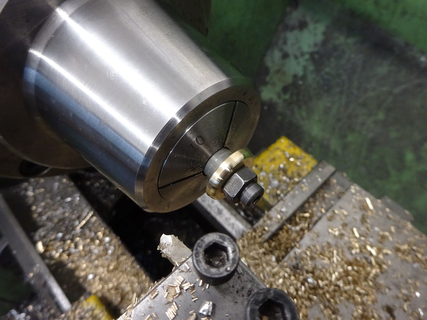
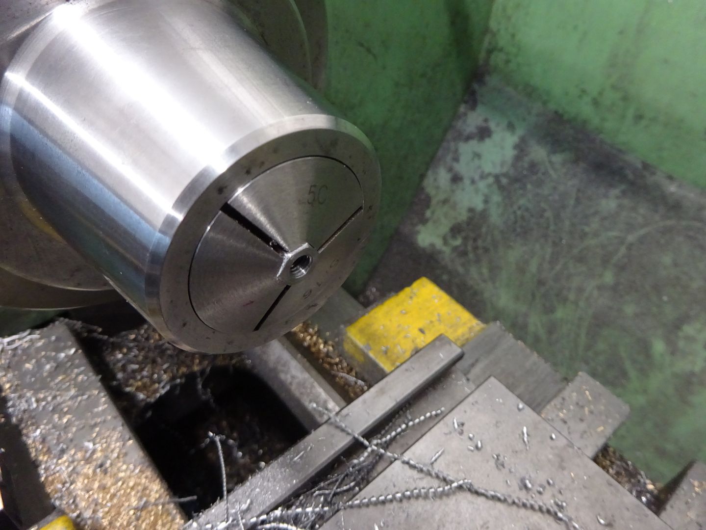
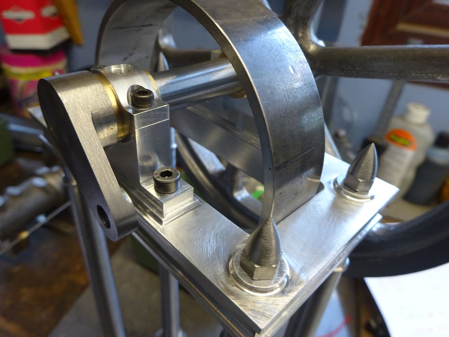
The M5 acorn nuts were made from round bar milled to one size smaller hex (7mm) and then the ball turner was used to shape them, the triangular insert has the advantage of leaving a nice chamfer on the top of the hex. After parting off they were held in a hex collet though a 3-jaw would do and drilled and tapped M5. While the ball turner was set up I also made two M3 versions to go on the top of the crosshead guide rods
Here are the bearings and nuts in place
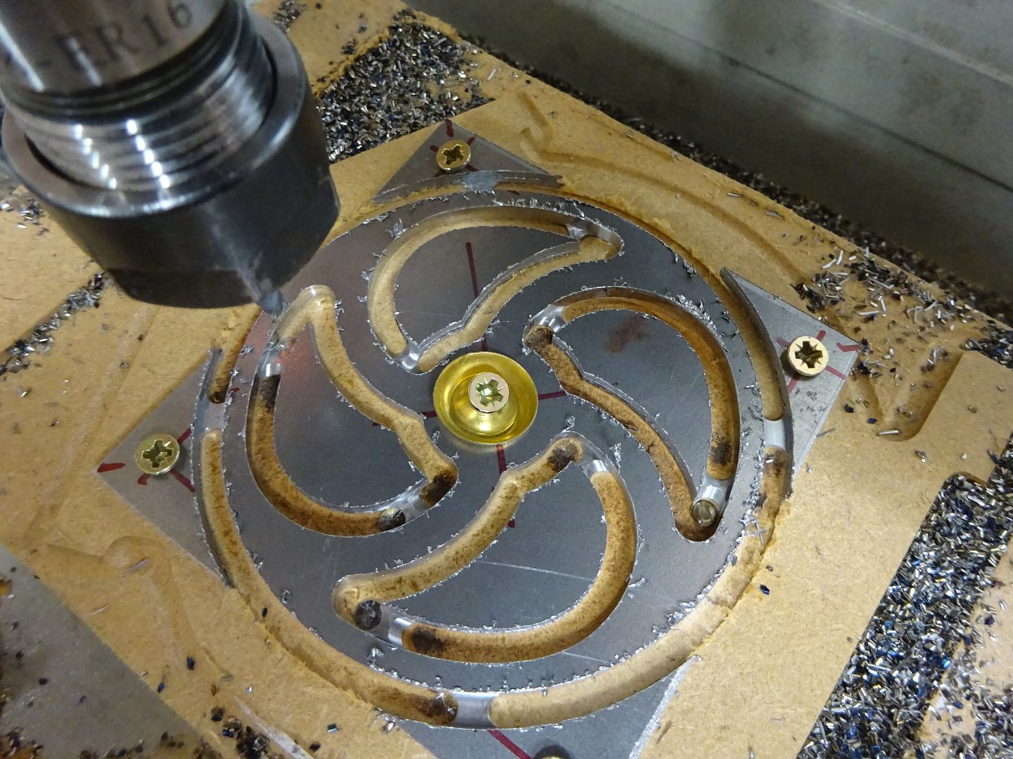
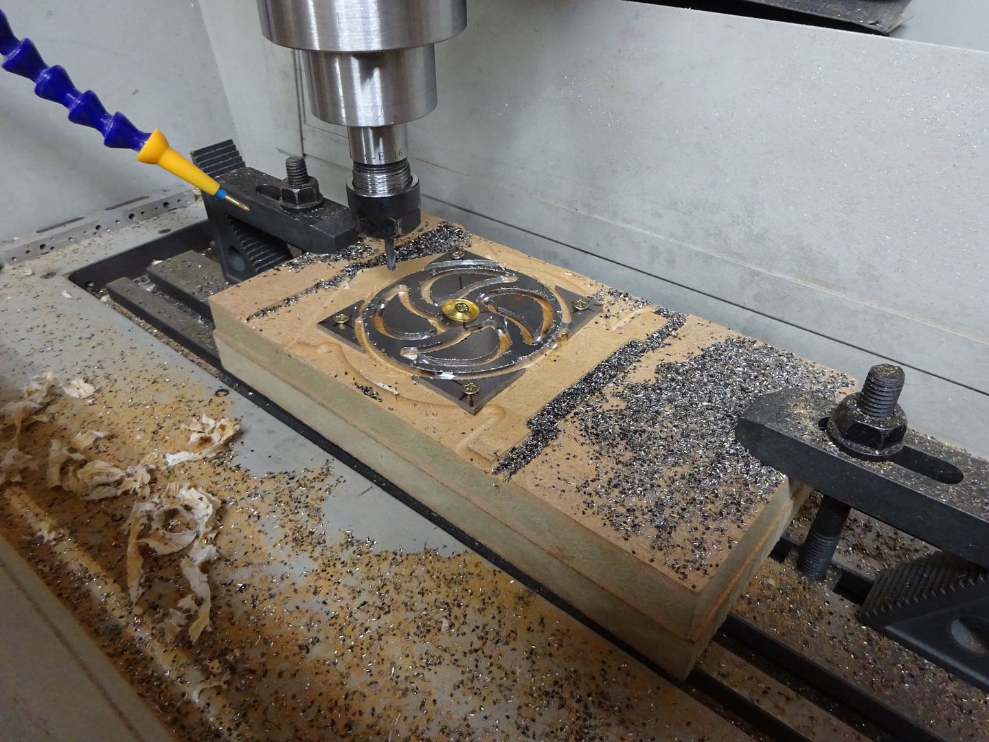
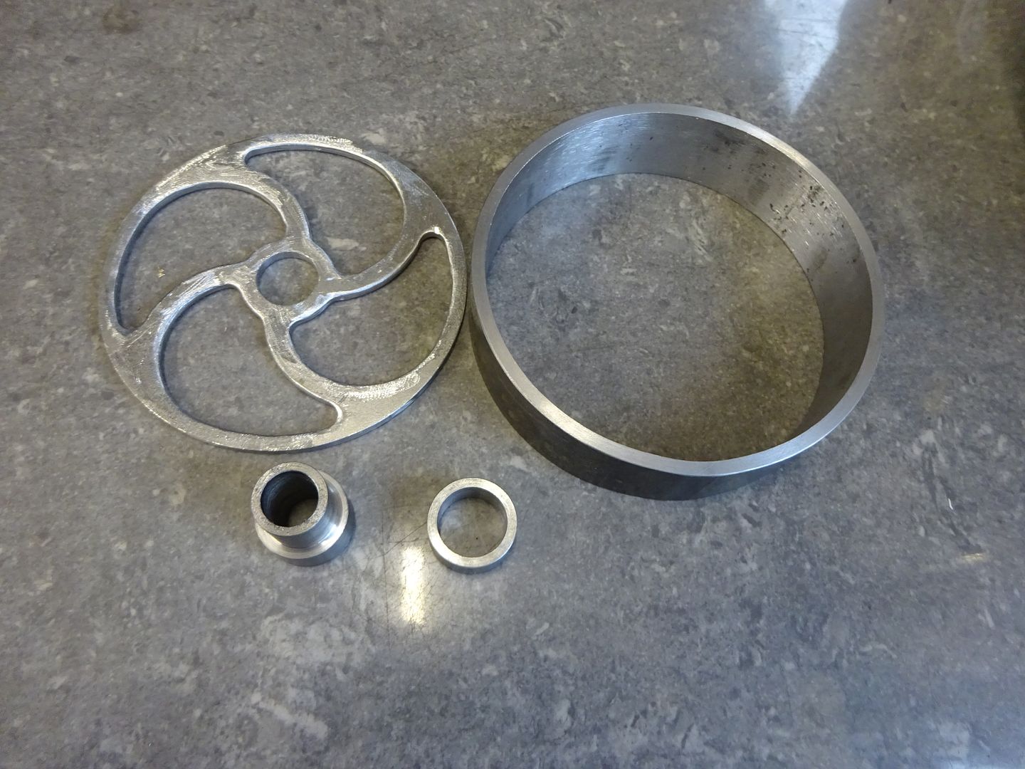
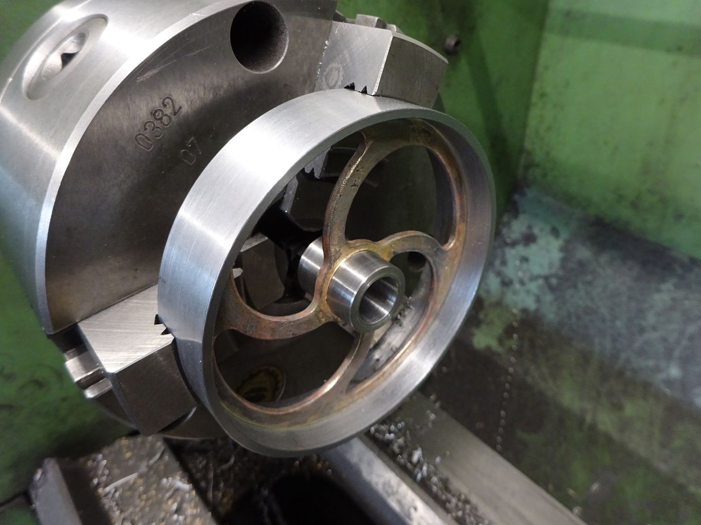
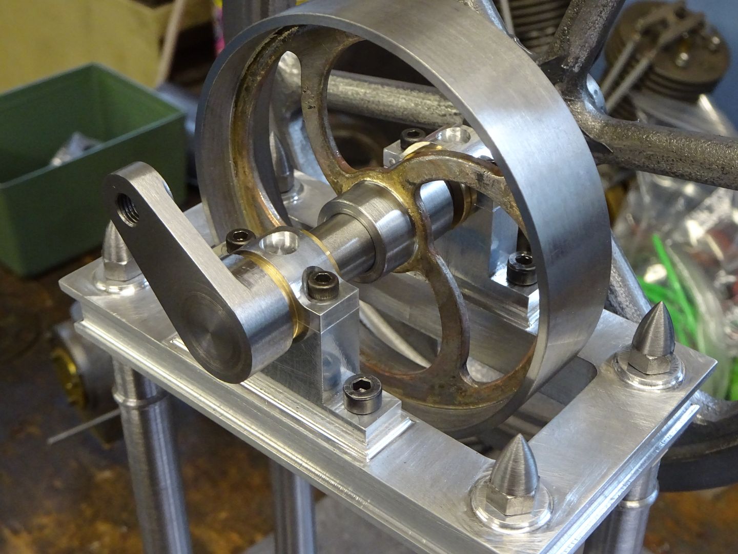
You may also notice in the above photo a slice of ERW tube which is the basis for the more attractive pulley rather than the standard cast Stuart item that they use on all the 2 x 1 engines. The spokes were cut from a piece of 2.5mm steel sheet which was quite easy on the CNC but all the curves are parts of circles so could be done on a rotary table.
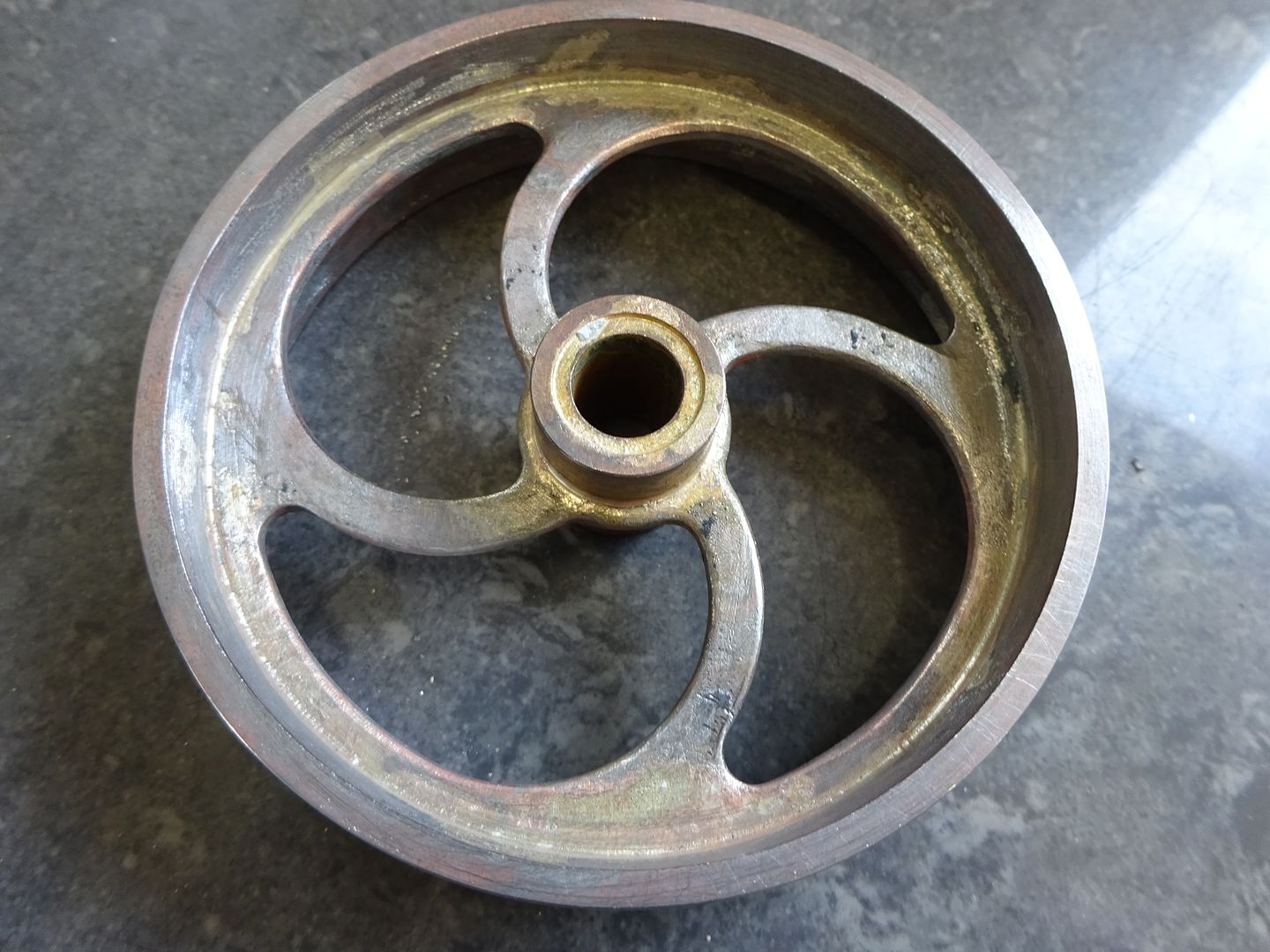
After a bit of "softening" with the dremel and turning two bits of steel that will form the hub all were ready for soldering.
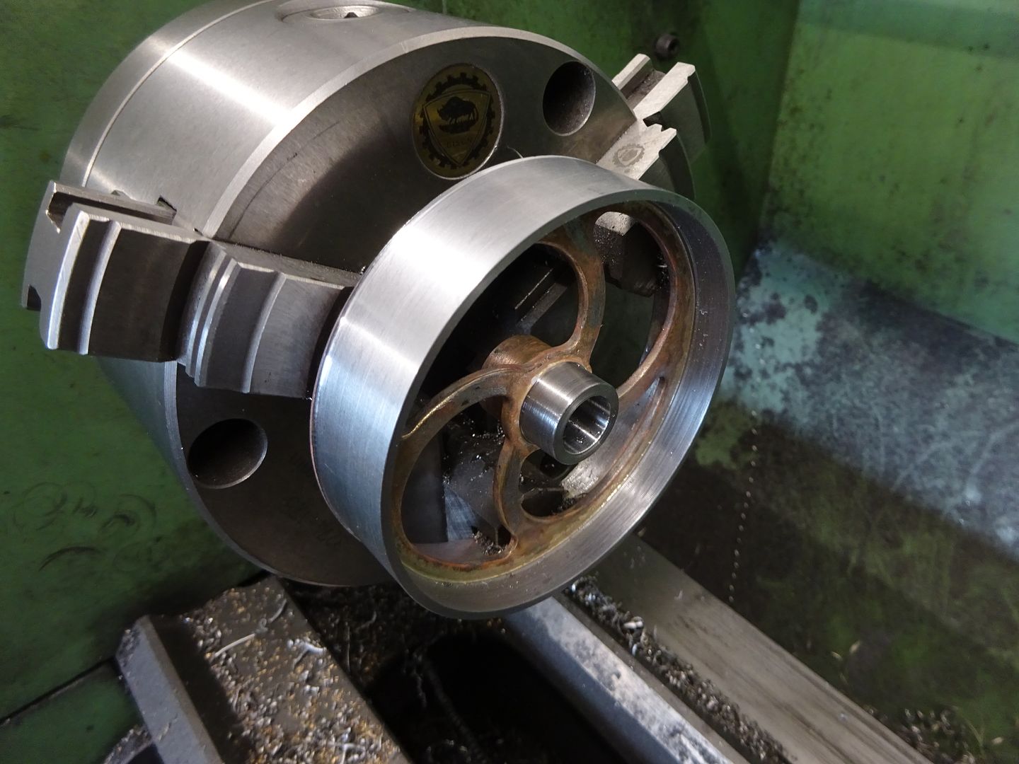
held in the 3-jaw the outer face was cleaned up followed by the edge of the rim & hub and finally the undersize hole in the hub was bored out to fit the crankshaft
I then swapped to external jaws so that the other side could be finished
That's another part that can be crossed off the list.
12 June 2022 at 17:16 #601464 JasonBModerator@jasonb
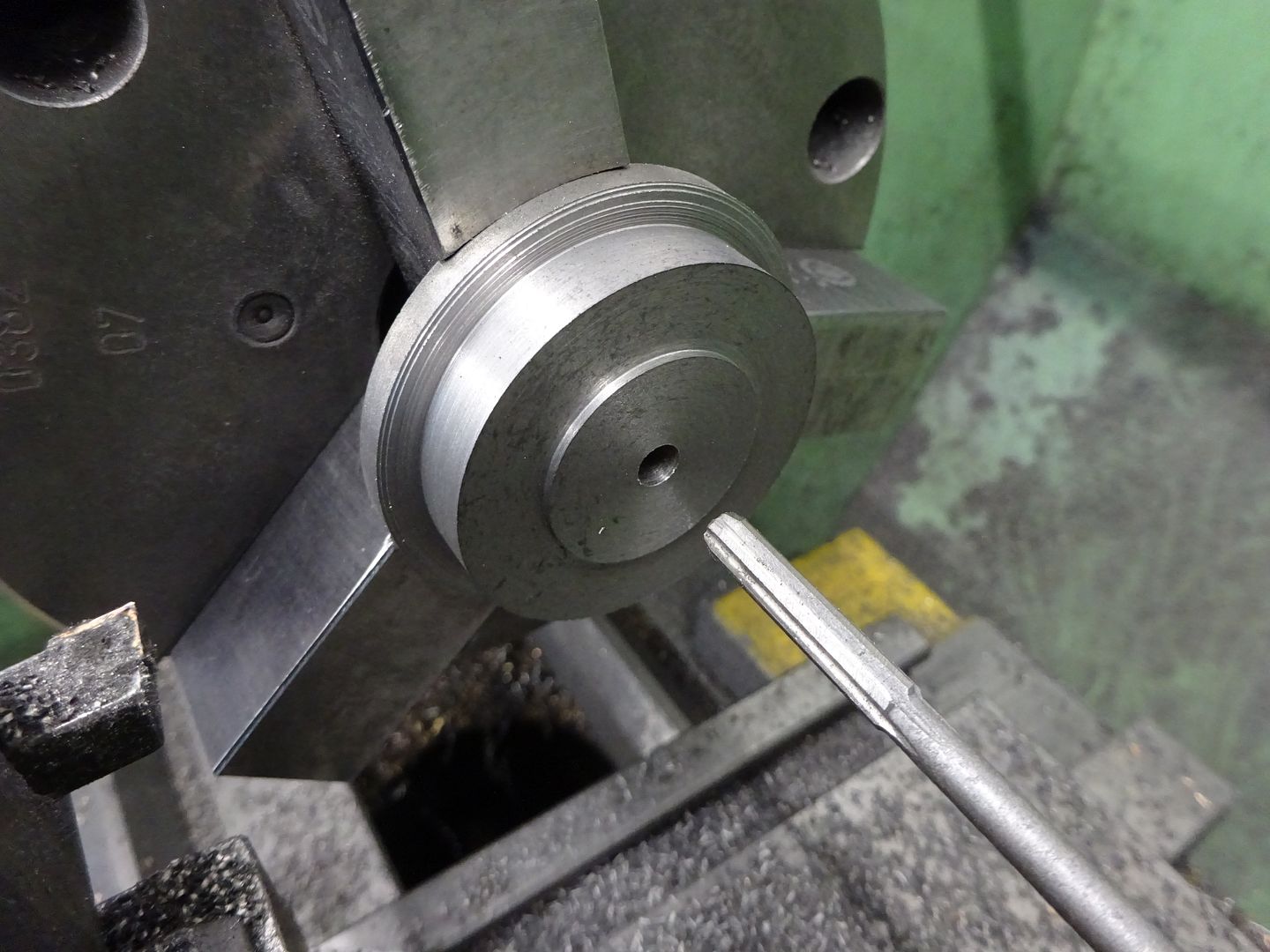
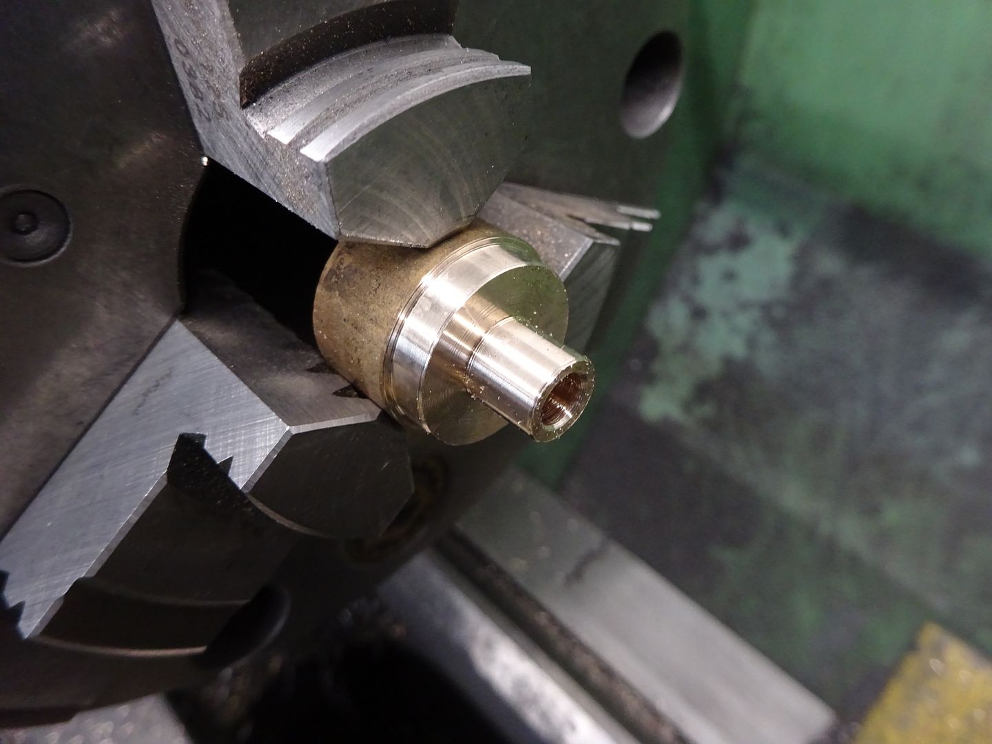
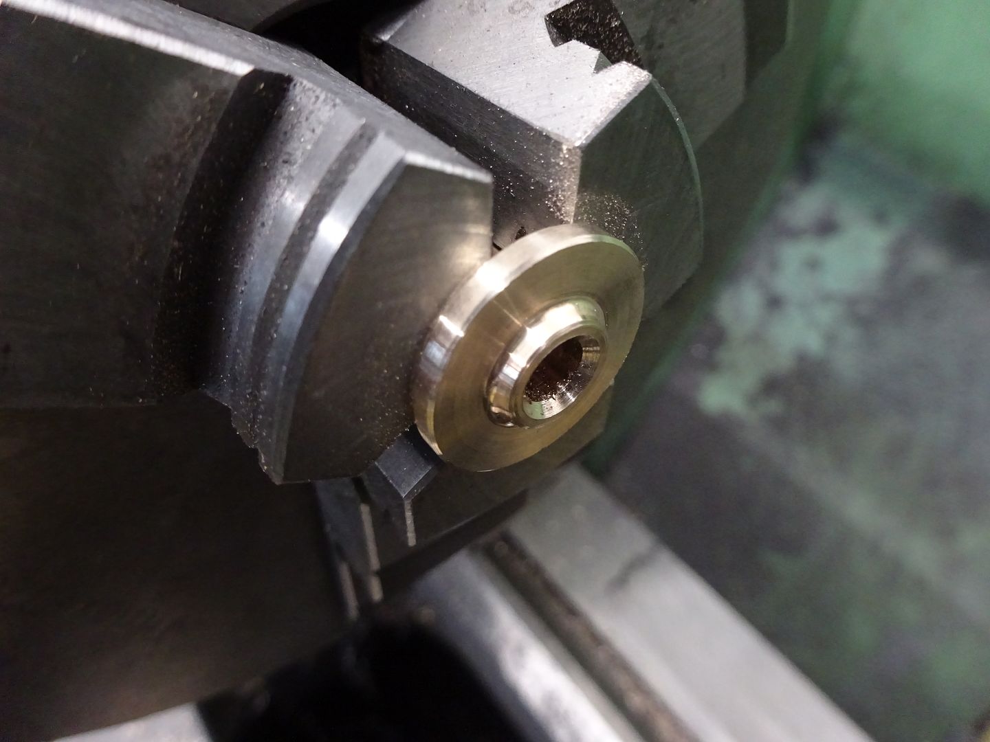
A slice of CI was held in the soft jaws and turned to the diameter of the cylinder top cover, then faced and the spigot cut. I then spotted, drilled 4.8mm with a stub drill and finally took the hole out to the required 5mm diameter with a machine reamer.
Now holding the other way round the boss for the gland was turned leaving a flat area for the nuts, I used a brazed carbide tool with a rounded nose to get the larger fillet at the base of the boss.
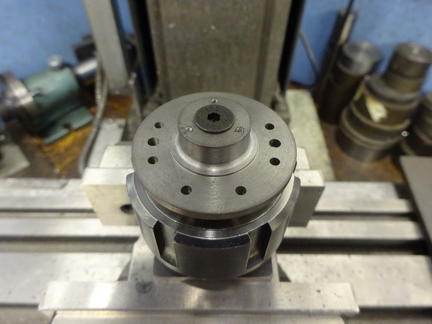
With the cover screwed to an arbor which in turn was held in an ER32 block the outer edge was kept clear so the edge finder could be used to locate the cover's ctr then set about drilling some holes. 8 @ 2.5mm for the studs, 2 @ 3mm which were CSK on the underside for the cross head guide rods and 3 @ tapped M1.6 for the gland studs
The gland was quite straight forward turning to fit the cover and reaming for the piston rod.
Then held the other way round to face off, add a decorative spigot and CSK the hole to encourage any oil back into the cylinder rather than running over the engine.
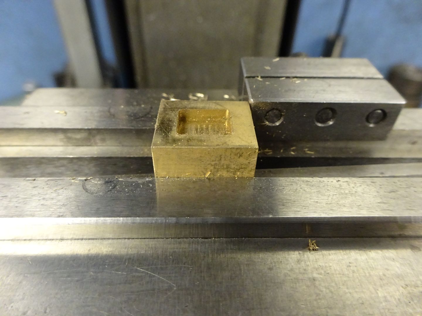
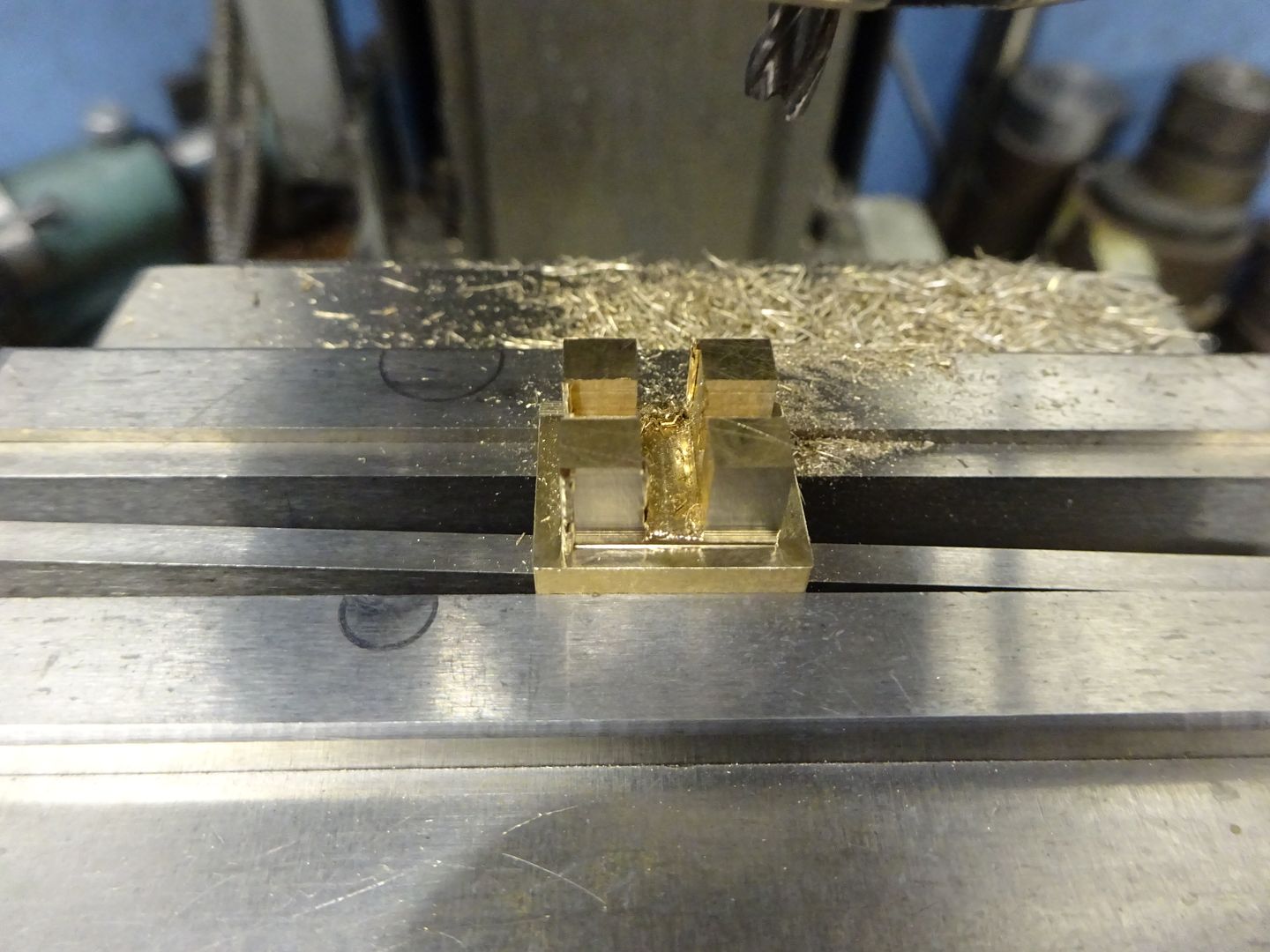
Another small part tackled at this stage was the valve, just a piece of bronze milled to the overall size and then the recess milled into one face with a 2mm dia cutter
The opposite face had slots cut to clear the valve rod and at 90degrees to that one to take the valve nut which was just a offcut of brass left from the eccentric strap.
15 June 2022 at 19:25 #601883 JasonBModerator@jasonb
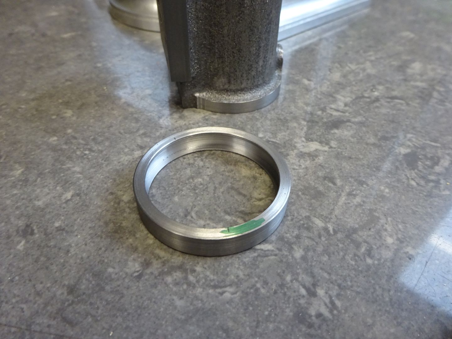
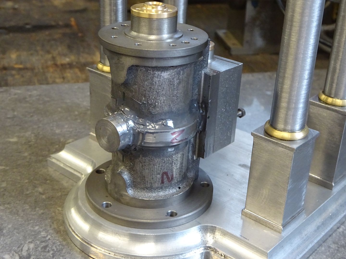
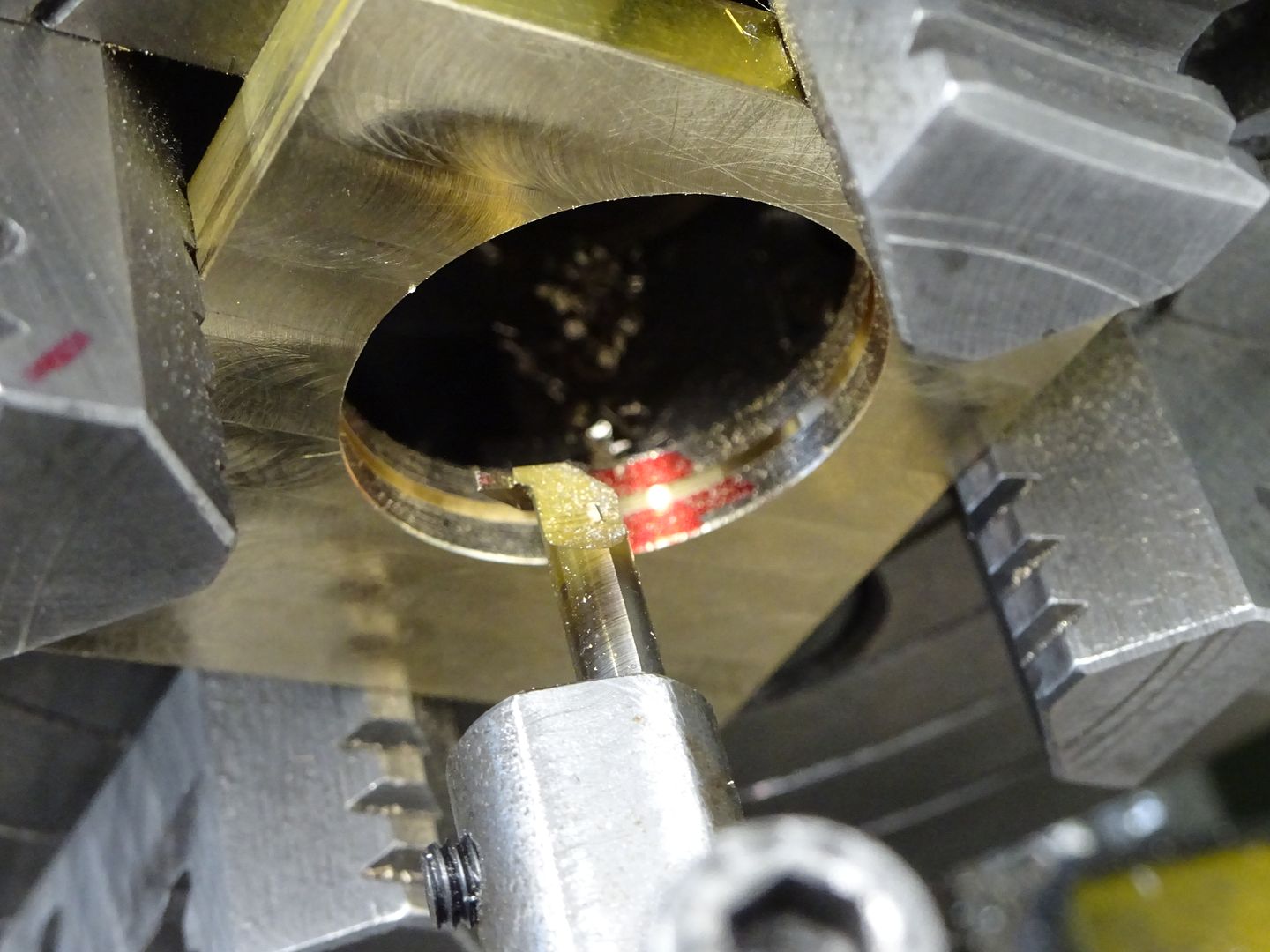
Returning to the cylinder and it's time to reposition the exhaust connection from the of the valve port face to the opposite side of the cylinder which is a bit less cluttered by columns and the now repositioned inlet. A piece of steel was turned to the same diameter as the cylinder end flanges then bored to the average diameter of the cylinder body. I then used an internal grooving tool to hollow it out to a sort of rectangular "U" section.
A 14mm diameter was turned onto the end of a bar and the boring head used to cut a radius to match the outside diameter of the cylinder.
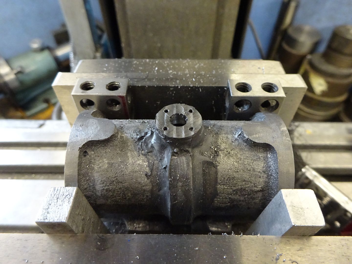
Then holding it in a collet block two grooves were cut that would allow the air/steam to flow from the new passages around the cylinder into a drilled hole in the boss and then out to the plumbing.
After sawing a couple of pieces off one end was cope cut to suit the 14mm dia exhaust boss and then the other ends fitted by filing until they sat nicely against the back side of the portface.
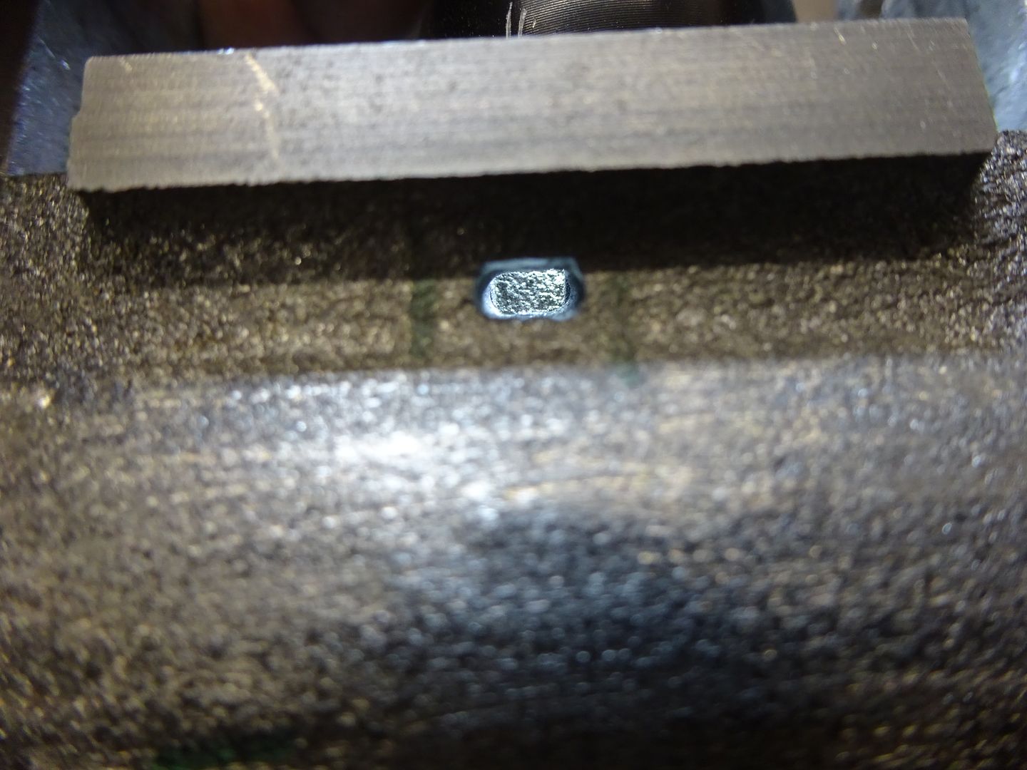
Two holes were then drilled on either side down to meet the central port. I used CAD to work out the angle of the holes and set the cylinder using an angle gauge.
Finally a bit of needle file work had the two holes formed into a slot – too deep to get all the way with a milling cutter. At the design stage I had made sure that these slots, the new ducts and the slots in the boss were all greater in area than the smallest port the air/steam would have to pass through so as not to restrict flow.
It was then time to boost Ramons shares in JBWeld and stick the new bits to the cylinder casting. I have a few plastic spatulas that I have cut different corner radii on plus some rods with rounded ends and use these to get a basic fillet which saves time filing and sanding hard JBW
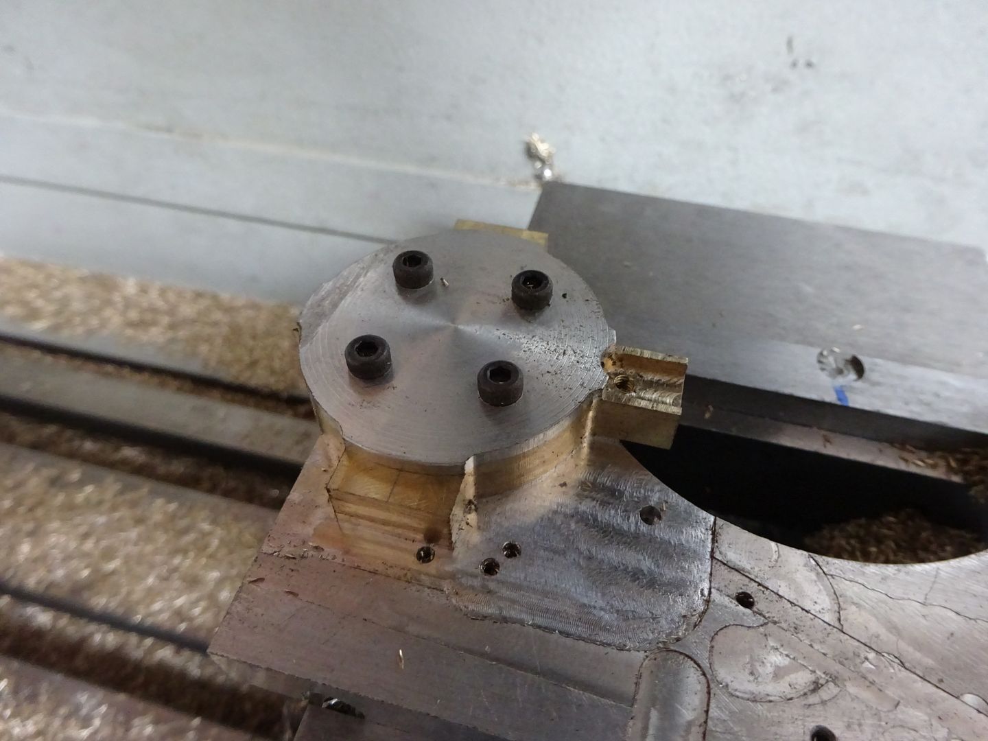
Once set but before tidying up the JB Weld I milled the boss back to the required length and drilled and tapped for four M1.6 studs to retain the flanged pipework.
17 June 2022 at 17:03 #602135 JasonBModerator@jasonb
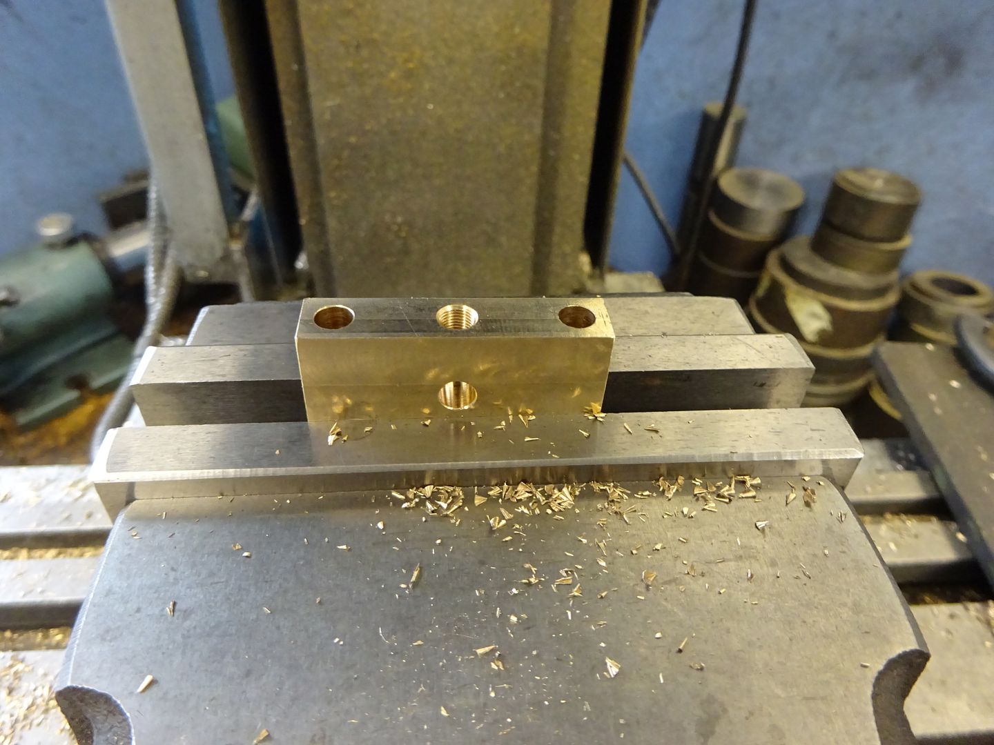
As I mentioned when dealing with the valve chest I'm mot keen on Stuarts way of guiding the valve rod end in a hole that is a long way from where you can hold a drill bit so another option was needed. I decided upon a similar guide to that seen on the No1 which is a bracket that makes use of two of the cylinder studs to hold it in place.
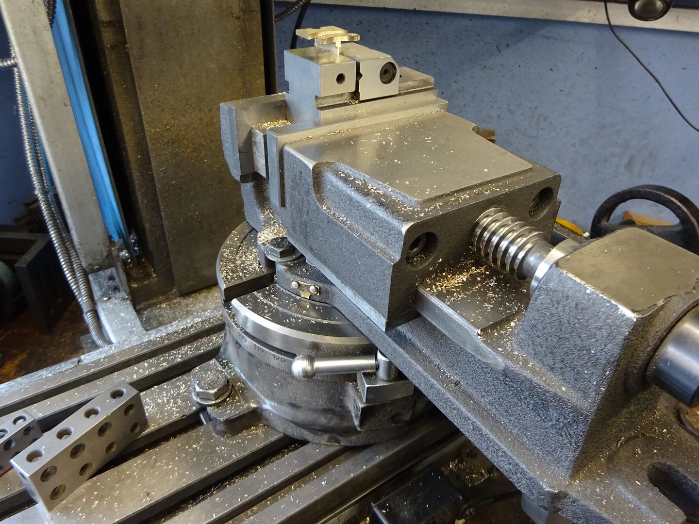
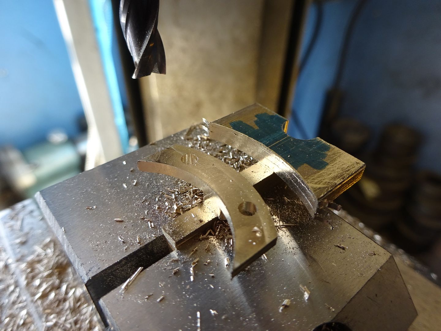
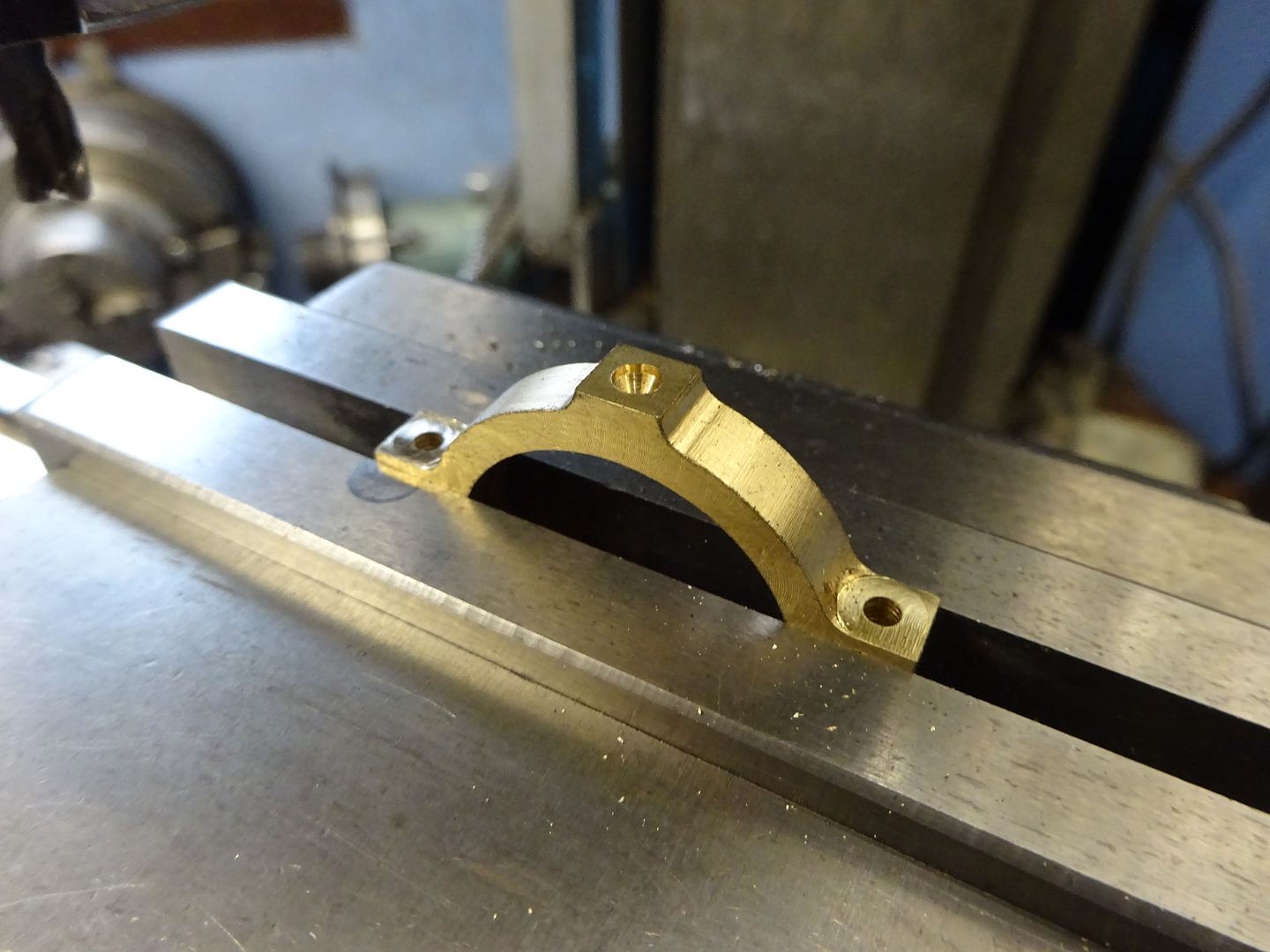
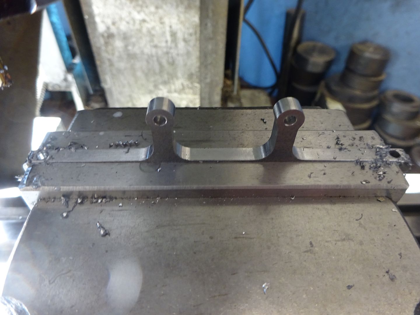
I started by thinning down a short length of Tee section brass though two separate bits could be used. I set up the rotary table and bolted a vice to that. Then another smaller vice to hold the tee section so a semi-circular notch could be cut on the overhanging end, two mounting holes drilled and then the rotary table used to cut the two arcs.
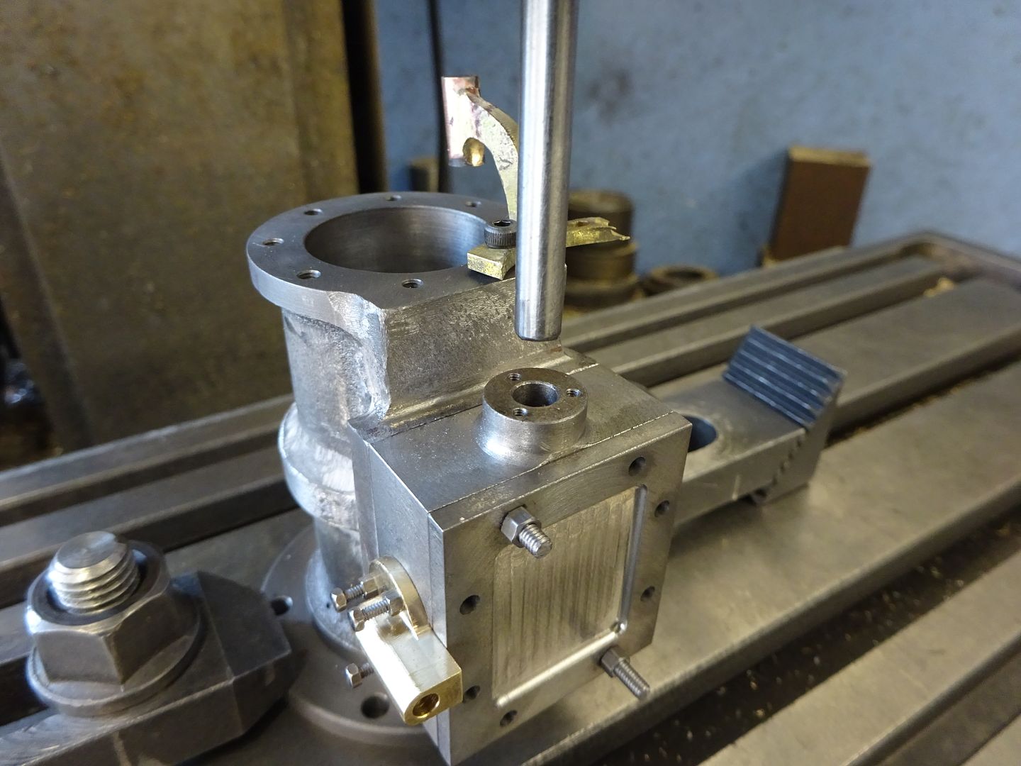
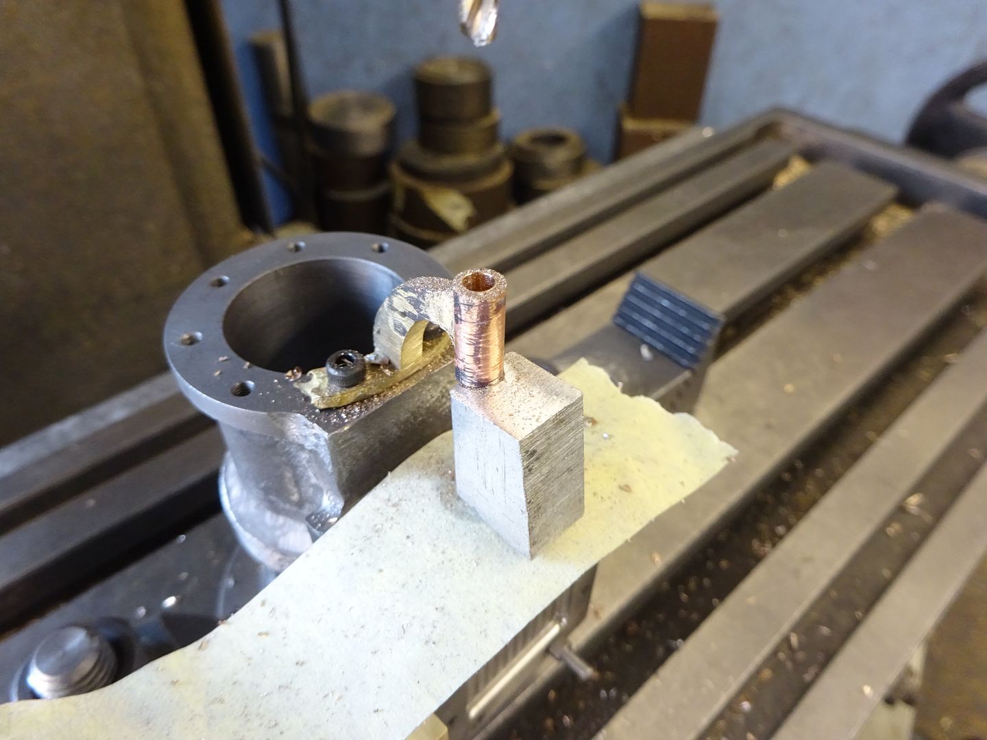
After a bit of rough shaping I silver soldered a length of bronze rod to the end. To ensure that the valve rod ran nice and true through the guide I first set up the cylinder complete with valve chest on the mill and located the valve rod hole with a short length of silver steel (drill rod) held in a collet and locked the slides. You can also see the beginnings of the inlet elbow in this photo, just needs the D section rounding and a flange soldering on.
I then swung the bracket round into position and screwed it on tight. With some packing under the end so it did not sag it could then be drilled out to take the rod.
A bit of final shaping and rounding over the ends of the curved bottom were all that remained to do.
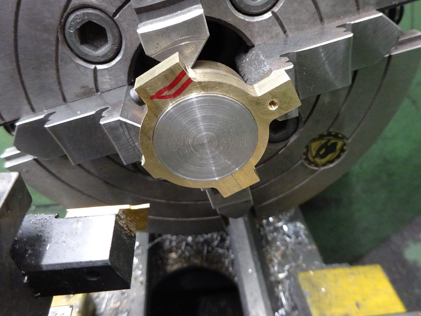
The eccentric strap started life as two pieces of brass that were soft soldered together before milling to the desired thickness and adding a ctr hole.
This hole was used to get the strap running true in the 4-jaw so it could be bored out and then a grooving cutter used to form the groove that the ridge on the eccentric will run in
A quick and dirty top hat bush was made to hold the strap while the outside profile was milled another job for the Rotary table of CNC if you have one. I also cut a recess for the valve rod which helps get a straighter run for the rod thus avoiding the dog leg of the Stuart design
The last job before unsoldering was to drill and tap the two lugs and ctr drill the top to form a small oil pocket.
19 June 2022 at 19:00 #602383 JasonBModerator@jasonb
Now that the strap was complete it could be used to gauge the size of the eccentric. After facing and turning to the required OD a small parting tool was used to create the central ridge which stops the strap moving sideways first by plunging and then by moving sideways with shallow cuts.
The size was adjusted until the strap would fit but not bind when tightened together.
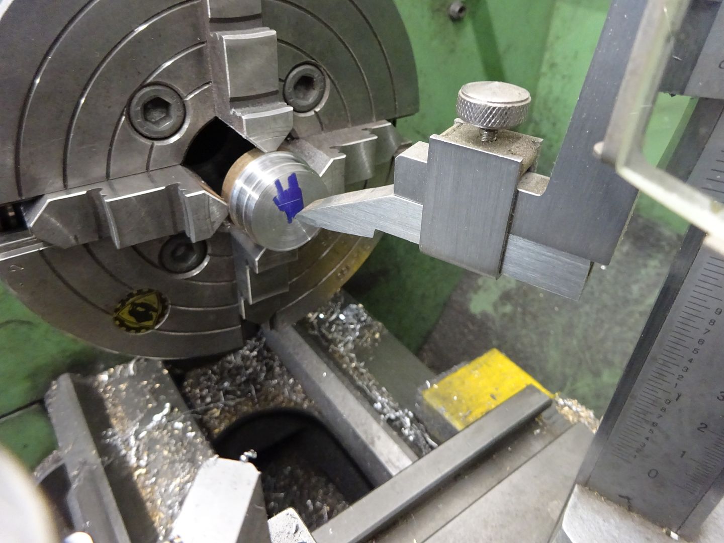
I then used the height gauge to scribe the offset centre before punching the intersection and then setting the punch mark to run true in the 4 jaw so the hole for the crankshaft could be bored.
After drilling for a grub screw the eccentric could be mounted onto a stub of bar so that the boss could be turned down to finished size.
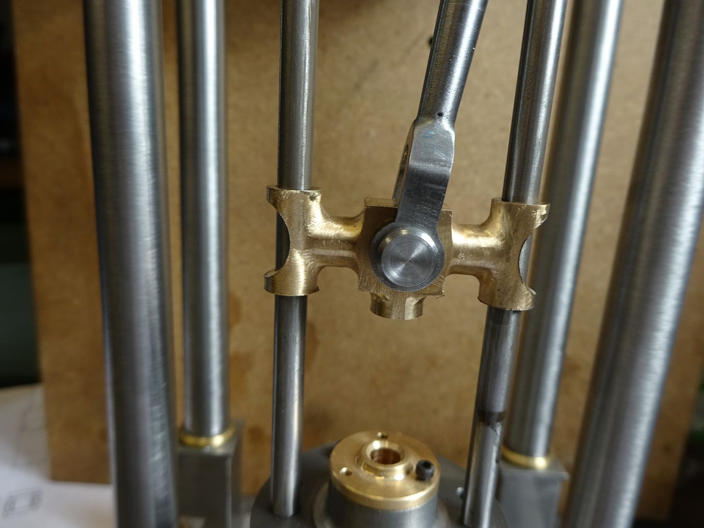
A piece of bronze was machined square and then the two holes for the guide rods reamed, piston rod hole drilled and tapped and at right angles a hole for the cross head pin was reamed.
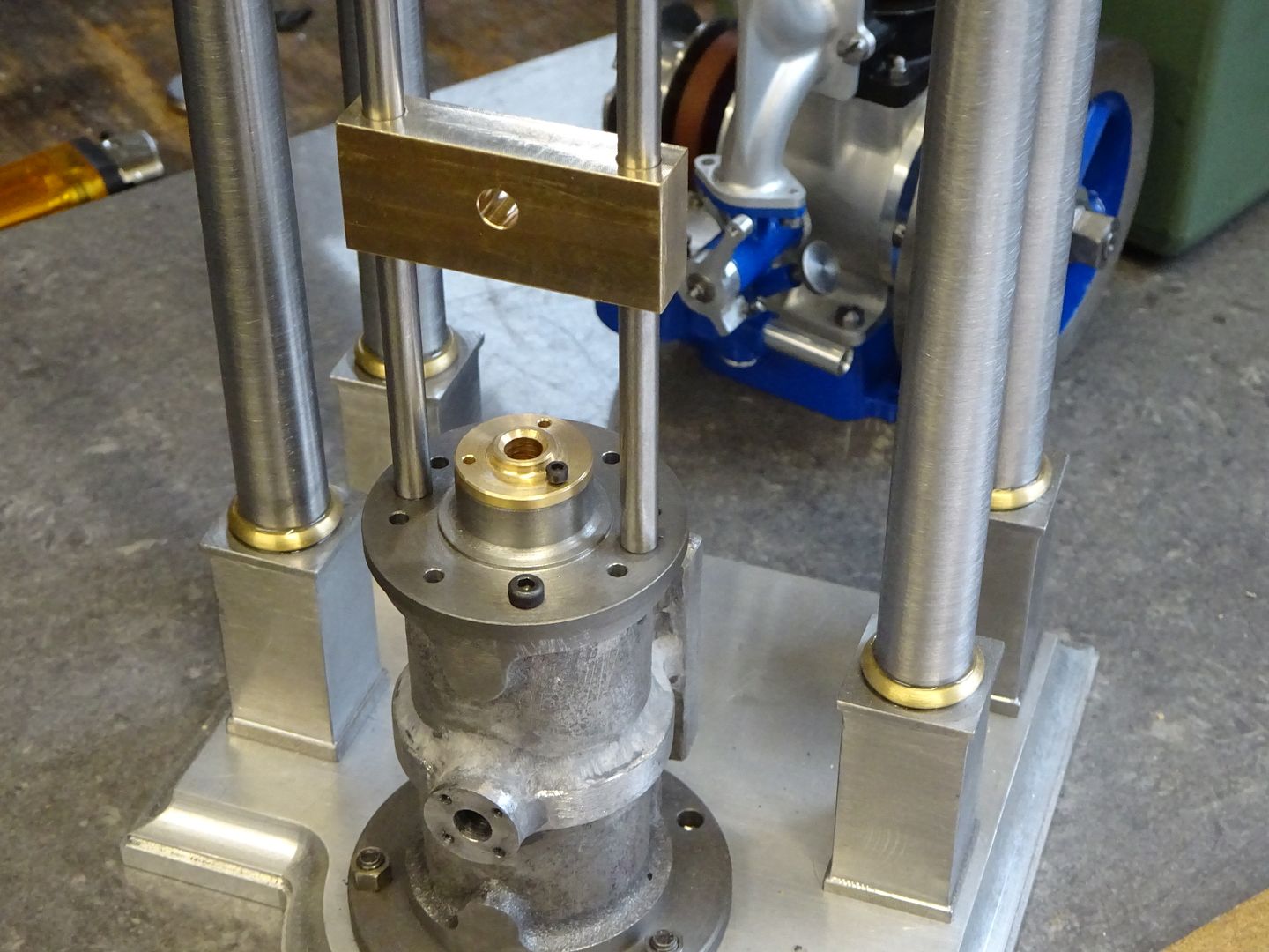
The guide rods are just pieces of 5mm silver steel drilled and tapped M3 at each end afire carefully turning to the same length. They are held yo the cylinder cover by CSK screws from below and studs and nuts through the brace at the top. A quick test before shaping the crosshead and all seemed well with it moving smoothly up and down the guides.
The top bracket was cut from some 5mm flat bar to a shape that pleased my eye, a lot easier than bending up one as per The Stuart design. Here it is having the last two holes drilled for the studs that will hold it to the columns.
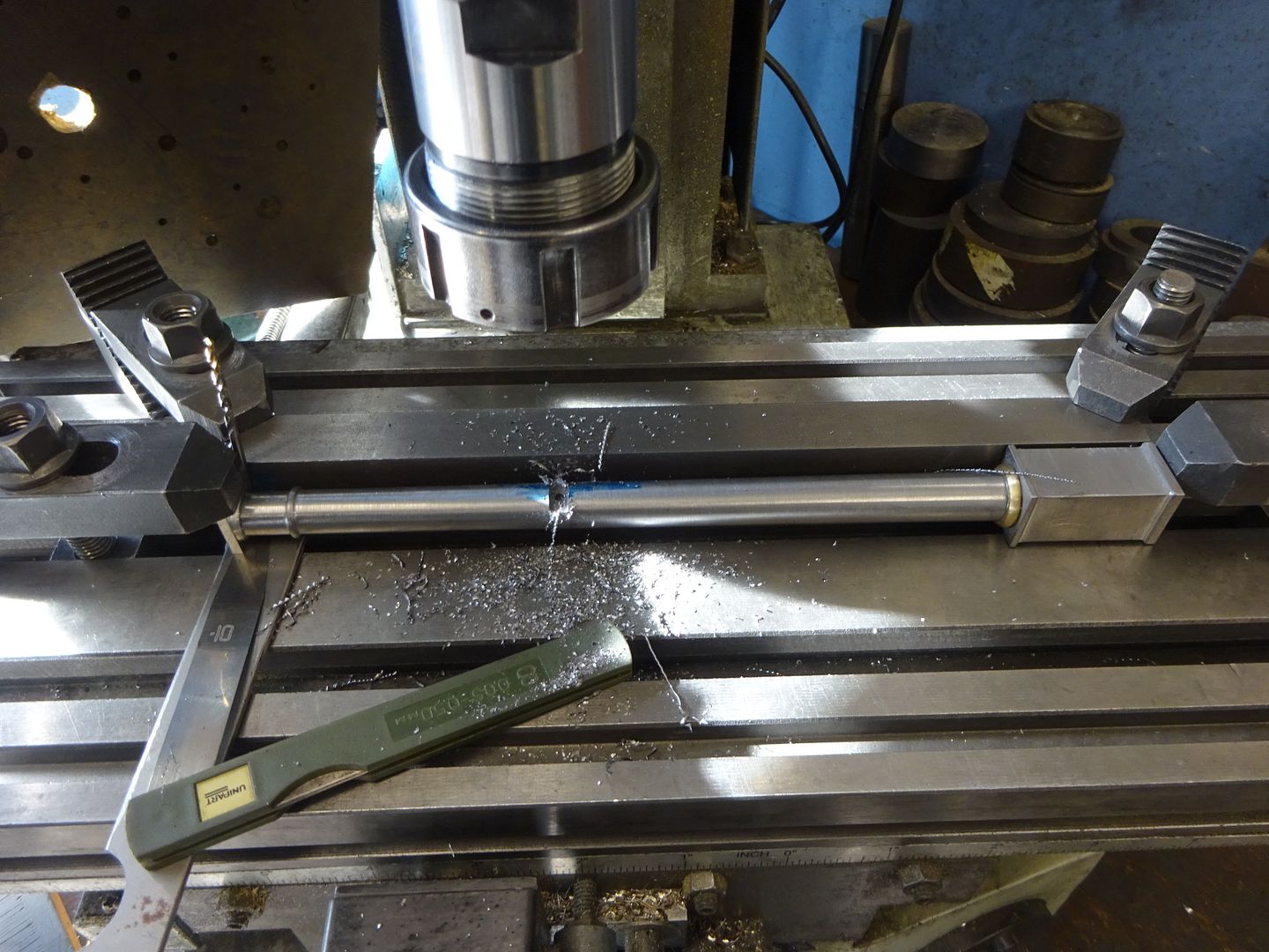
To ensure that the top brace was in the correct position slots had to be cut into the tapered part of the columns. To do this I first clamped a straight length of bar to the mill table and clocked it true. Then packed the smaller top end of the column both up and away from the straight edge so that it's axis was true along the mill table. It was then just a case of milling a 5mm slot and drilling and tapping for an M3 stud.
The cross head can be shaped however you like and will in some ways be limited by the available tooling if not your imagination, this is what I went with which was done with a mix of manual and CNC mills. Both this and the eccentric will be bead blasted to give them a nice satin look.
19 June 2022 at 23:14 #602400Neil Lickfold
Participant@neillickfold44316Such a nice thread with lots of pictures taken. I often forget to take pictures, and then sometimes I think one has been taken but has not. I don't have soft jaws for my home lathe and use rings , either spilt or distortion type. I was confused by the JB weld needed and obviously have missed something for it being a bonded part and not part of the initial casting. When using JB weld, if I wet the profile and wipe it around, the finish will get a nice shiny surface. To prevent slumping, I have it at close to 15c as possible, and then after the initial cure, place it in a small oven on defrost mode 45-55c for a few hours to help it get to full strength. At times I have also added micro balloons or some other light weight filler to the left over JBweld for filleting. It also will reduce the slumping that can occur. Where you used the inverted boring tool, is also a good use for left hand external turning tools too. There are so may ways to make a part as well.
Thanks for taking the time to create this thread and showing how you like to make things and set up to be able to make it in the home shop.
20 June 2022 at 20:05 #602511 JasonBModerator@jasonb
Thanks for the interest Paul. Nice to get the odd response a sit can seem like I'm posting to myself.
You can also let the JBWeld sit for a while after mixing which allows it to firm up a bit so it doe snot slump so much. I usually bring the items in and stand on a window cill above a radiator to help with setting particularly in the winter when the workshop is not so warm.
For decorative fillets that don't need the strength of JBW or it's heat resistance I tend to use car body filler as it's easier to sand of a putty like Milliput which is easily shaped with a wet tool.
Not far to go now
 20 June 2022 at 20:19 #602513
blowlamp
Participant@blowlampJason.
Don't think we aren't watching. I'm quietly appreciating the great job you're making of this model.
Martin.
22 June 2022 at 06:15 #602661DiogenesII
Participant@diogenesiiI study all your build threads. Always something useful to take away, thanks for taking the trouble.
22 June 2022 at 18:18 #602712 JasonBModerator@jasonb
Thanks for the posts and a couple of PMs too. Good to know people are following along and getting something out of the build threads. For those that enjoy looking at the photos they do tend to come up quite a bit larger on MEM forum in case you are missing any detail. There may be a few comments there that relate to other posts and comments made but the actual build thread is the same, for example someone recently suggested that Indian made tooling was not fit for use as a boat anchor, I just let the finished parts and models produced with such tooling do the talking

The last major component is the conrod. as I have changed the crosshead design there will be no need to make the "tuning fork" shaped one of the original which had to be shaped that way to clear the extended piston rod. There are a few options for conrod designs but I decided to keep to something fairly simple and came up with a rod that is not too far removed from that found on other Stuart engines like the Beam and Victoria.
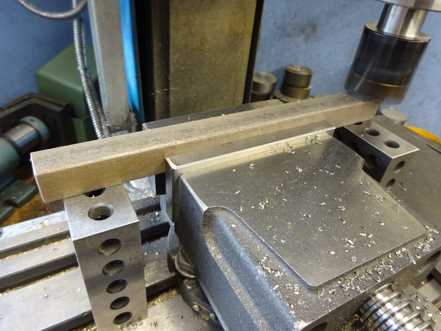
Starting with an over long length of 16 x 16 black (hot rolled) bar which was pickled for a while in brick cleaning acid to remove any scale I set it up in the mill vice and brought it down to the maximum size rectangular section needed to get the part out of. I flipped it over a couple of times to take equal amounts of opposite sides and that combined with the black bar meant it remained straight.
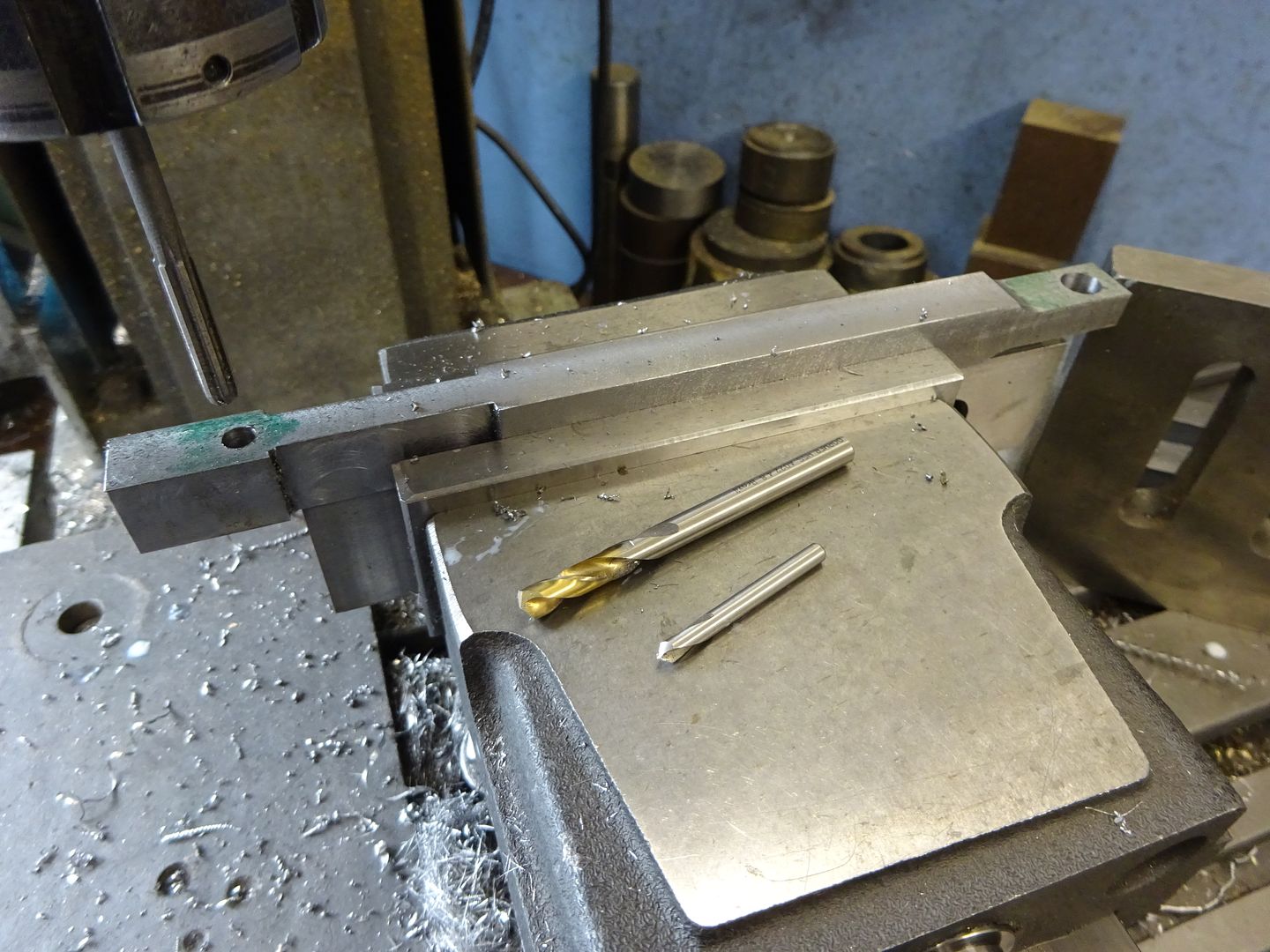
After reducing the areas around the big end (right of image) and the small end (left of image) to their overall rectangular size I spotted, drilled and then reamed the two holes. I have left some excess to the left which will allow me to hold it for turning, this gives a more solid setup than turning between ctrs and means the interrupted initial cuts don't seem to knock as much plus you can take heavier cuts to get it down to round. You may be able to make out an angle plate (mounted at an angle) on the right, this was used as a stop to maintain position in Y as the part was turned in the vice.
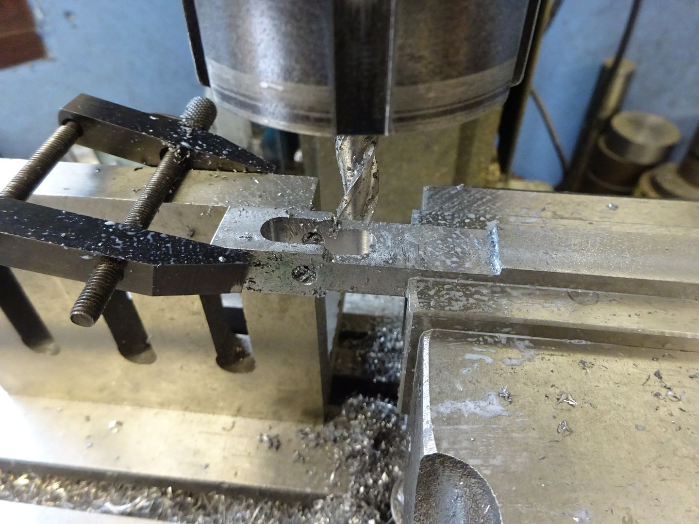
With the rod rotated 90deg in the vice I then milled a slot which will form the forked end once the chucking material has been removed. I've clamped the end to another angle plate jost to make sure the overhanging end is as rigid as possible so there is less chance of any cutter chatter.
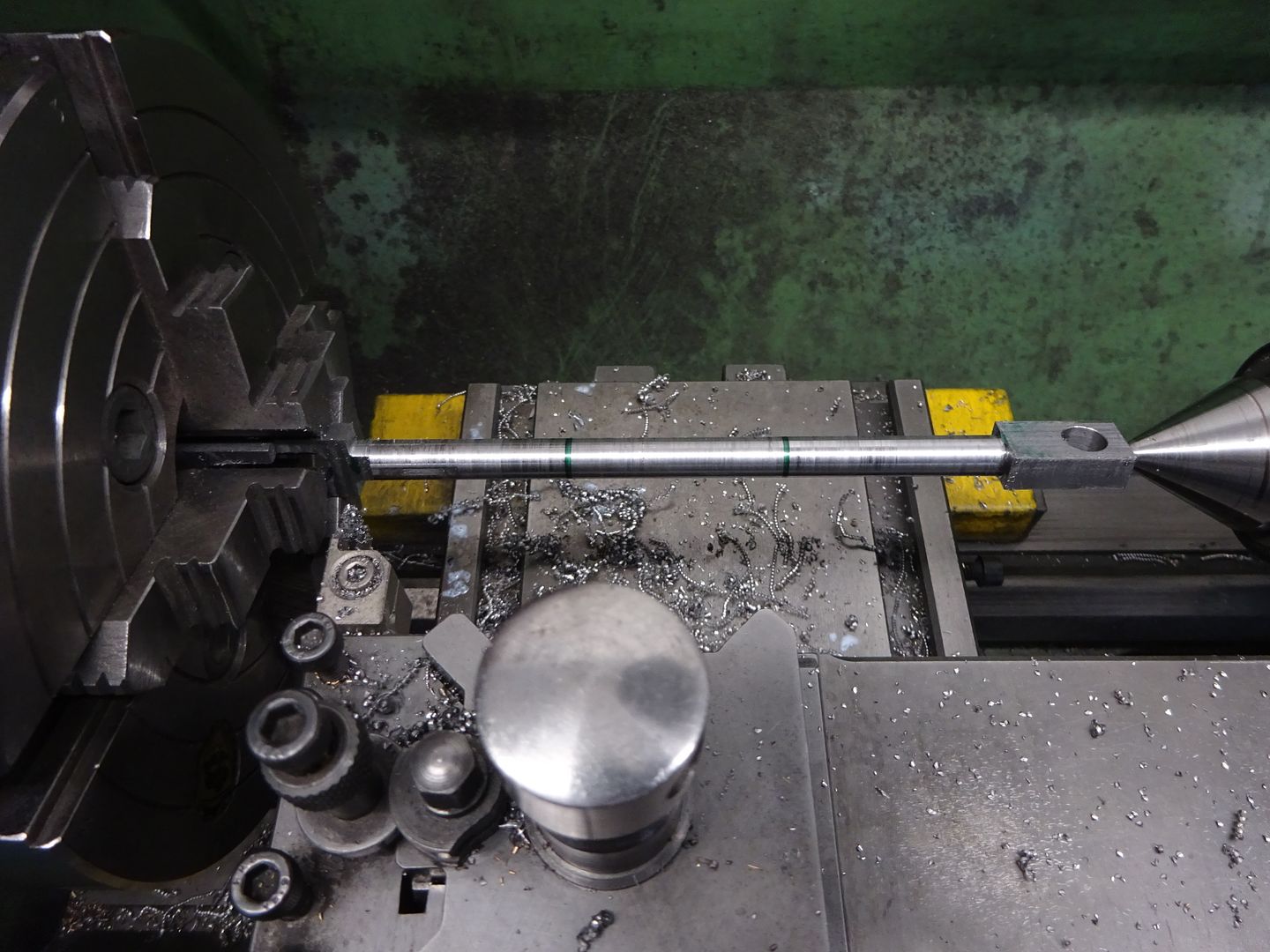
With the job now held in the 4-jaw chuck and supported at the other end with a revolving ctr it was turned to the largest diameter of the "fishbelly" and then a Sharpie used to mark approx 1/3rd in from each end. You can also see that I have left the rectangle section at the crank pin end a bit longer than the Stuart ones so that I can put in two dummy strap bolts rather than one.
The topslide was then set over a few degrees and one end tapered followed by setting it the opposite way and tapering the other 1/3. I use an insert with a 2mm dia end so that a nice fillet was left in the transition from round to rectangular. All that remained was to blend the three facets with files and then emery to get a smooth looking fishbelly to the rod.
Having the extra SX2.7 mill in the workshop I tend to leave the ARC rotary table and chuck on that so it's a quick setup to mount anything that needs rounding over on one of the many arbours that I have built up over the years and round the ends on the mill. here I have a sacrificial washer between arbour and work so the cutter can have it's end just below the work and the M8 nut at the top is unlikely to be much use for anything now but I've got a big pile of them. Rounding was done with full depth cuts, 1mm stepover for the first few and then reduced to 0.5mm once the nut started to get cut too.
The forked end was rounded in a similar way after sawing off the chucking piece and then just a bit of file work to blend the outside of the fork into the round rod and get the fork to look "U" shaped.
24 June 2022 at 20:35 #602974 JasonBModerator@jasonb
Having just seen the latest collaberation with Graham C come to life I best get on and finish this one to make room for another project, A proper oil burning Robinson HA, the first runs can be seen on facebook. Not sure if this link will work
I'm a bit of a fan of aluminium pistons in engines both IC and steam as they do reduce the reciprocating weight so starting with some 1" 6082 bar the end was faced, spot drilled, drilled tapping size right through and then counter drilled 5mm (piston rod size) for about 1/3rd the piston thickness before being tapped M5 with a spiral flute tap.
After sawing off a length the sawn surface was faced and a counterbore turned so that a lock nut can be used on the piston rod but not hit the cylinder end cover.
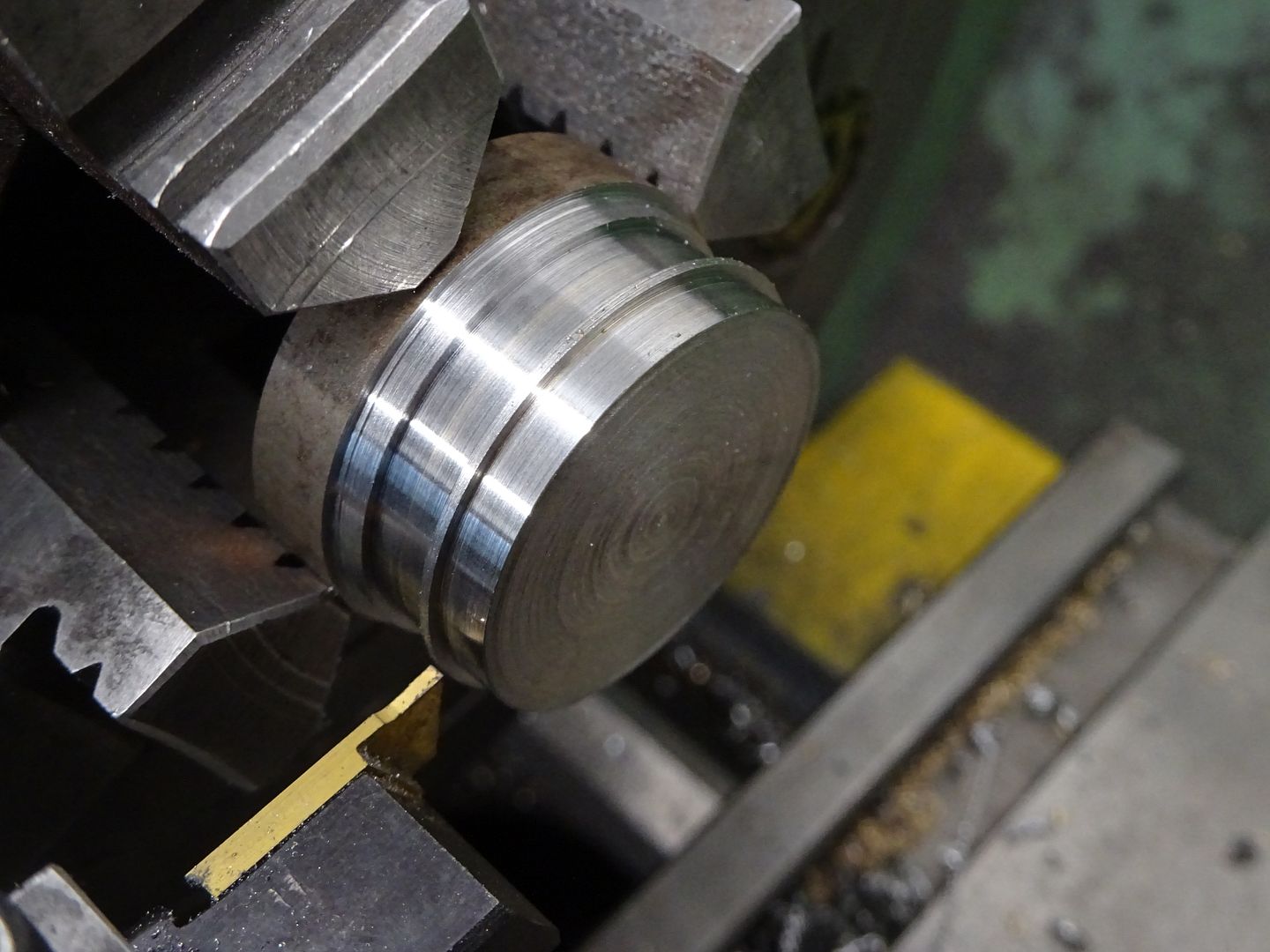
The piston was then screwed onto the previously prepared stainless steel piston rod and locked with a thinned down nut never to be taken apart again. Then holding by the rod in a collet and with tailstock support the OD was taken down to 25mm using the cylinder to once again gauge the fit followed by cutting a groove for an O ring
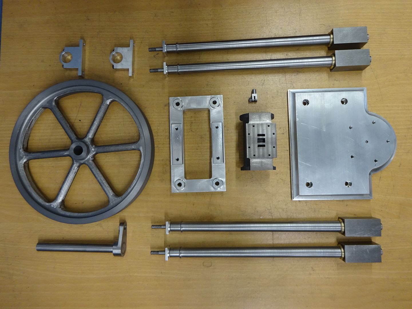
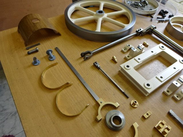
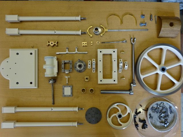
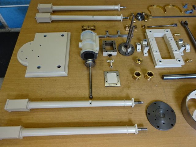
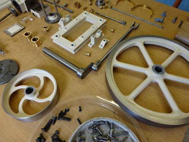
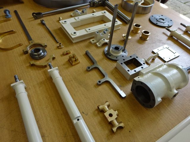
Well that covers all the parts I took specific photos of but there are a few others which luckily seem to have all migrated to this corner of the group photo.
The Eccentric rod is just 1.5 x 5mm section reduced down from the next available stock size, drilled at both ends (one CSK) and then rounded over.
A couple of pins for the crosshead, valve rod/eccentric rod, etc are just basic turning. A couple of flanged pipe fittings, I decided just to do short stubs and not fully plumb in the engine.
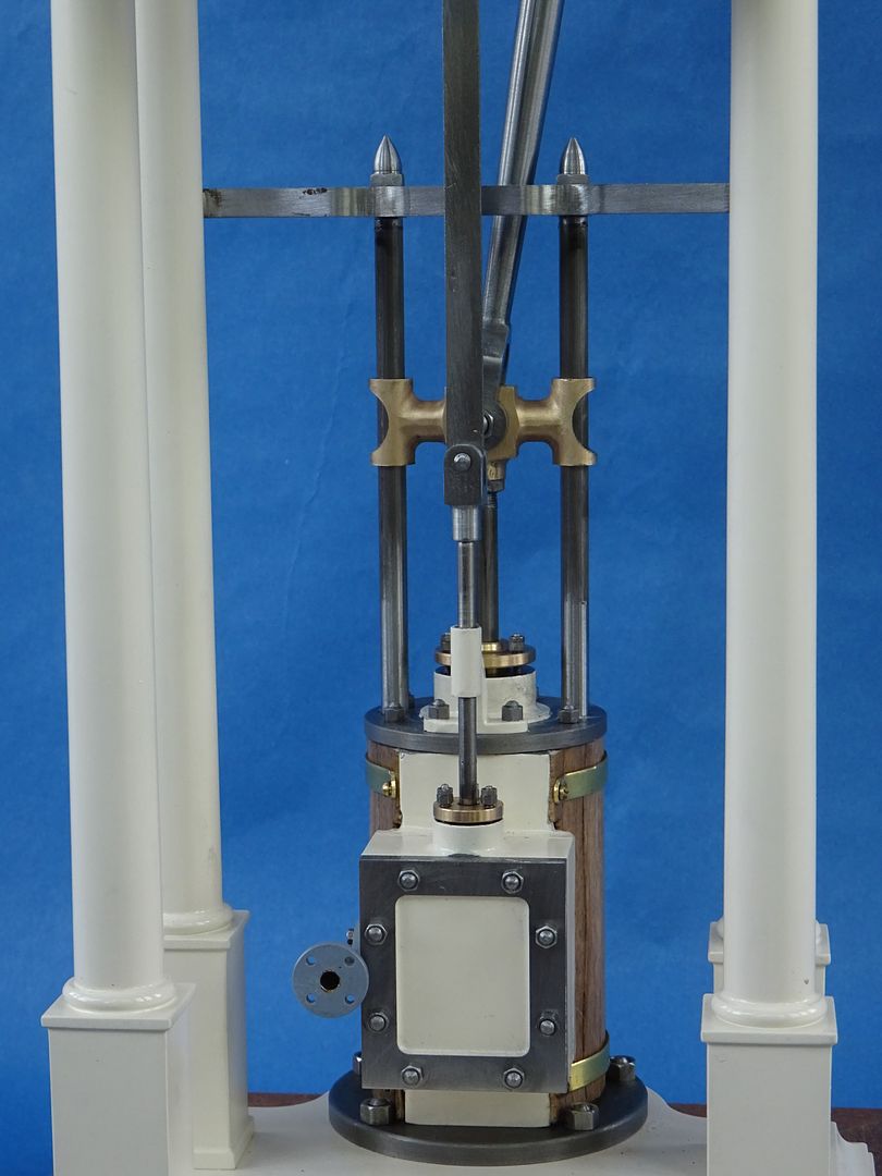
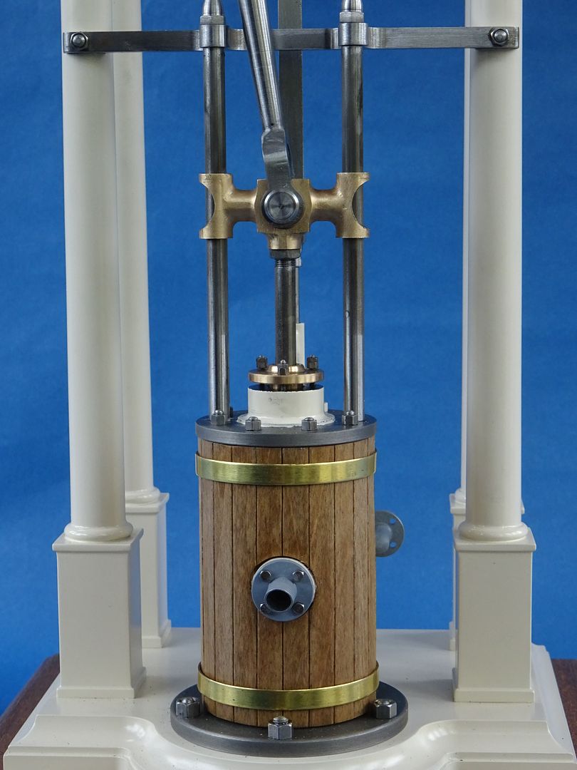
There is also the cylinder cladding which was some veneer that I cut up into planks with a scaple and stuck onto some thin linen which makes them easy to handle as one so they can be cut to a card template. The brass bands hold the cladding in place.
Edited By JasonB on 24/06/2022 20:48:56
24 June 2022 at 20:36 #602975 JasonBModerator@jasonb
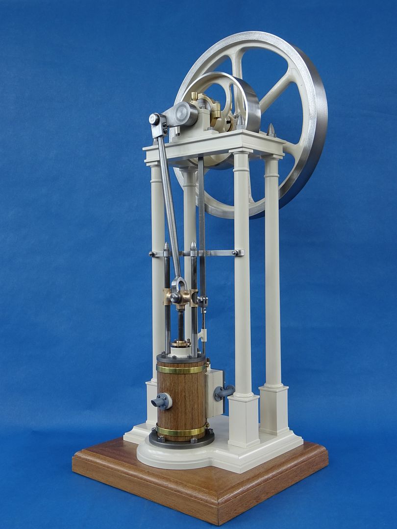
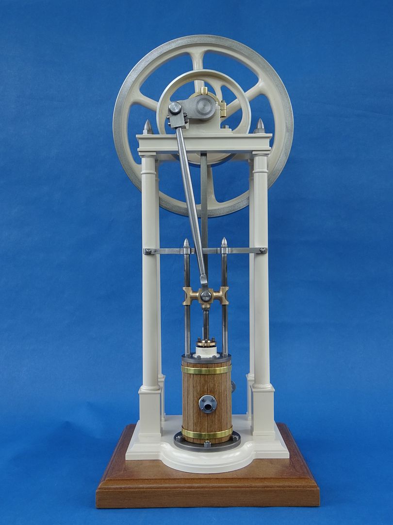
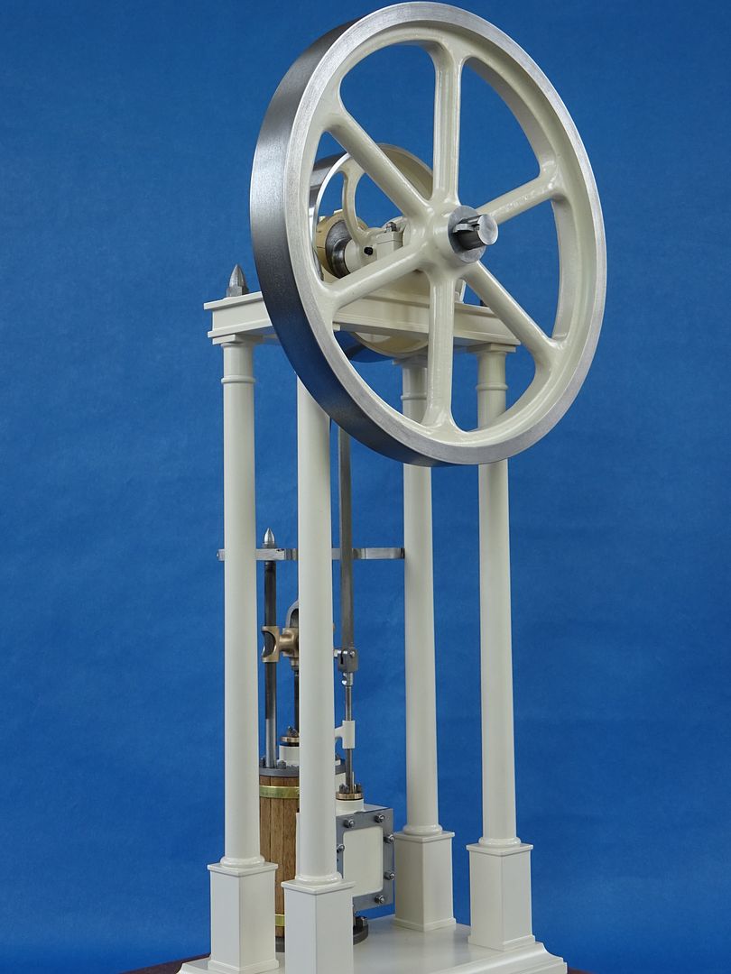
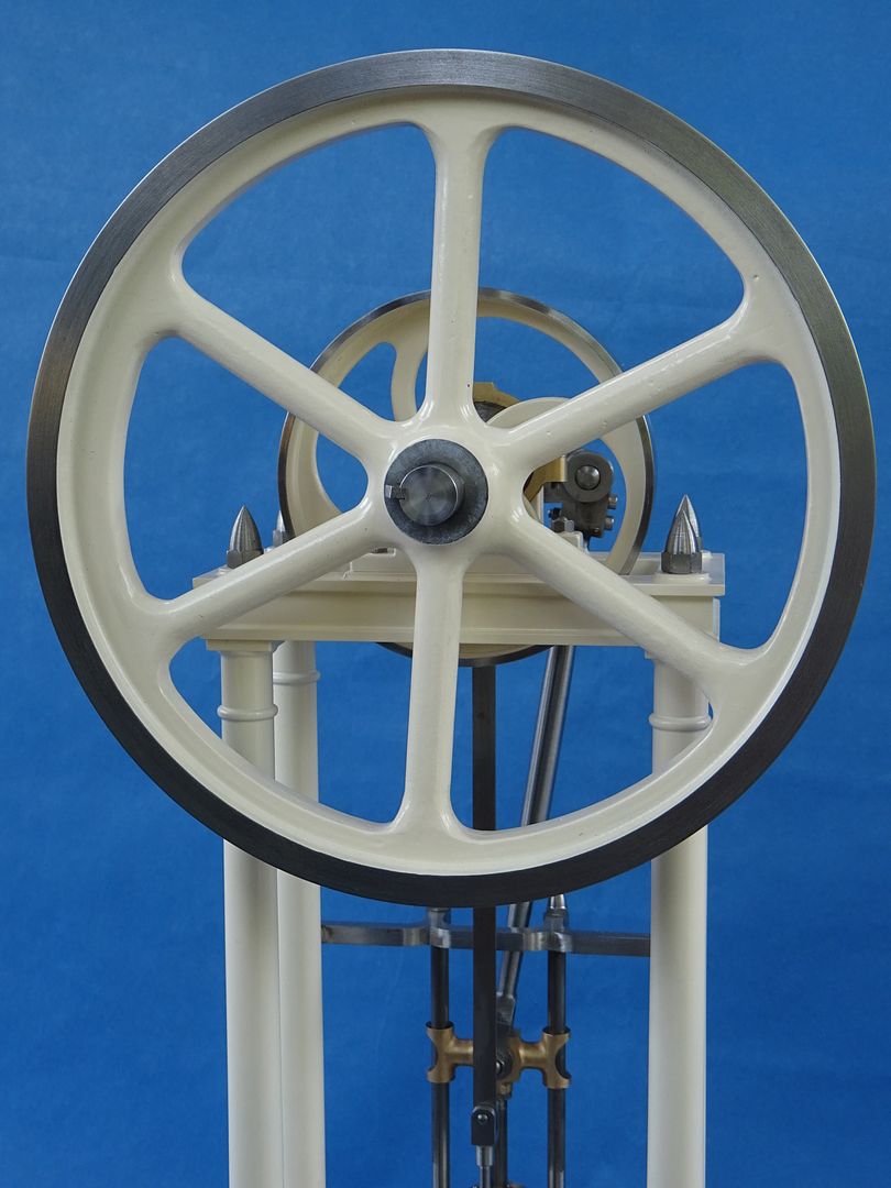
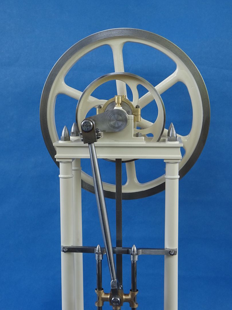
The keen eyed will have spotted that I went with an off white paint colour for this engine, Ford "Ivory" was what caught my eye in Halfords. Non ferrous metal was primed with Upol Acid8, the Flywheel and cylinder with Upol High5. Bothe were then given a coat of Halfords white primer as were the remaining steel parts to get a uniform base for the topcoat.
A few shots of the parts laid out prior to final assembly, the engine having been test run before hand as I like to sort out any issues if there are any without the risk of damaging the paint if you have to start pulling things apart a few times. All visible fixings are small hex metric, mostly studs and nuts which you can see in one container and those that don't show are socket head.
Well lets see what they look like all put together.
So that about wraps up the build. I'm happy with how it turned out and it has fulfilled my initial desire to show that an attractive and individual model can be built based on an existing design for about half what it would cost if you bought the full kit and you also get a lot more workshop time for your outlay.
I don't know how many of you are like me and enjoy looking at "naked" models (not that sort). Be it plastic AFVs, miniature figures or model engines I like to see them before they are painted a sit lets you see some of what has gone on in the construction as well as materials and methods used so here is a video of the early test run, just tacked together with a few screws, minor bits missing, no gaskets, packing or piston rings. It was also before I added the balance weight to the flywheel.
24 June 2022 at 21:34 #602982 Jim NicParticipant@jimnic
Another beautiful result Jason. I think that a good test of a stationary steam engine is how well it runs at slow speed and this one certainly is a smooth runner. Well done.
I always follow your builds and usually pick up a tip or two to help me to hopefully match your standard one day. Thanks for your postings
Jim
25 June 2022 at 09:06 #603014SillyOldDuffer
Moderator@sillyolddufferAnother excellent build thread and result. I've learned a lot from Jason and the gift keeps coming. I've not cracked the big secret though: how does he work so quickly? I'm still collecting materials for his Flame Licker. My theory is Jason is really Santa Claus and all the work is done by thousands of elves in a giant workshop at the North Pole…

Dave
25 June 2022 at 16:24 #603056 JasonBModerator@jasonb
Thanks for the comments.
I must admit I like an engine with a nice slow tick over, quite relaxing to just sit there watching them run. Though the IC engines are enjoyable to make and run they are not so peaceful to watch.
This is the Robinson Oil Engine I mentioned if the FB link did not work, set of castings are almost on their way to me. I did have a hand in some of the pattern making. At least it should smell good running on paraffin with hot tube ignition and eventually a spirit lamp to heat the tube.
Not sure when I'll start it as there are some others in the pipeline and I've now got an inkling to reinvent the James Coombes1 July 2022 at 18:02 #603830Dr_GMJN
Participant@dr_gmjnThat’s a beautiful result. It took me a while to find this thread – I know you mentioned it on mine a couple of times. I’d assumed it would be in “work in progress”.
No doubt I’ll have questions on broaching keyways when the time comes…
Cheers.
-
AuthorPosts
- Please log in to reply to this topic. Registering is free and easy using the links on the menu at the top of this page.
Latest Replies
Home › Forums › Stationary engines › Topics
-
- Topic
- Voices
- Posts
- Last Post
-
-
Machinery Handbook
1
2
Started by:
Dalboy in: Books
- 31
- 41
-
7 April 2025 at 12:18
John MC
-
Steam pressure using thermistor
Started by:
michael howarth 1 in: General Questions
- 9
- 14
-
7 April 2025 at 11:54
 Michael Gilligan
-
Elliott Omnimill Quill Clamp
Started by:
dangermouse in: Manual machine tools
- 5
- 10
-
7 April 2025 at 11:54
dangermouse
-
Reader Survey
Started by:
 Neil Wyatt
in: Model Engineer & Workshop
- 12
- 18
-
7 April 2025 at 10:58
parovoz
-
Easing out the bore of a 3-jaw, s/c chuck
Started by:
Greensands in: Workshop Tools and Tooling
- 7
- 9
-
7 April 2025 at 09:44
 Michael Gilligan
-
Hammant & Morgan “MINIPACK”
Started by:
 Michael Gilligan
in: Electronics in the Workshop
- 2
- 3
-
7 April 2025 at 09:02
 Michael Gilligan
-
Chester DB10LB Lathe – Not starting
Started by:
David Deaville in: General Questions
- 3
- 6
-
6 April 2025 at 21:50
Denis O’Kane
-
More Lidl questions
1
2
3
Started by:
old mart in: Hints And Tips for model engineers
- 26
- 57
-
6 April 2025 at 21:06
Nick Wheeler
-
Morse Key
Started by:
Steve Withnell in: Work In Progress and completed items
- 5
- 6
-
6 April 2025 at 21:00
duncan webster 1
-
Tangential tooling
1
2
Started by:
Keith Matheson in: Workshop Tools and Tooling
- 13
- 31
-
6 April 2025 at 20:50
Neil Lickfold
-
Myford Super 7 restoration problem.
Started by:
 Bootlegger Blacky
in: Manual machine tools
- 3
- 3
-
6 April 2025 at 20:47
Nigel Graham 2
-
Flattening brass plates
Started by:
t1krt in: Workshop Techniques
- 7
- 8
-
6 April 2025 at 20:36
old mart
-
Measuring increments on boring head
Started by:
Bill Phinn in: Workshop Techniques
- 15
- 22
-
6 April 2025 at 20:31
Pete
-
How to wire up 3 phase motor and 3 phase converter?
Started by:
ell81 in: Beginners questions
- 8
- 16
-
6 April 2025 at 20:17
old mart
-
Problem getting the right parameters on a VFD
Started by:
Robert Graham in: Electronics in the Workshop
- 8
- 12
-
6 April 2025 at 17:19
 Dave Halford
-
James Coombes Drawing Error (or mine?)
Started by:
Steve Withnell in: Drawing Errors and Corrections
- 5
- 8
-
6 April 2025 at 15:06
Steve Withnell
-
Supply company catalogues
Started by:
nevillet in: Workshop Tools and Tooling
- 5
- 8
-
6 April 2025 at 13:23
 JasonB
-
Which type of single phase motors are best for constant use – power hacksaw
Started by:
ell81 in: Beginners questions
- 5
- 5
-
6 April 2025 at 11:44
Clive Foster
-
Stripped aluminum threads. Now what?
1
2
Started by:
brucemc777 in: Beginners questions
- 19
- 35
-
6 April 2025 at 10:39
howardb
-
Damp proofing concrete floors
Started by:
Duff Machinist in: General Questions
- 13
- 14
-
6 April 2025 at 02:52
Duff Machinist
-
My week this week! My workshop videos
1
2
…
11
12
Started by:
Phil Whitley in: The Tea Room
- 14
- 286
-
5 April 2025 at 16:00
Phil Whitley
-
Myford S7 Taistock Adjustment
Started by:
 Harry Wilkes
in: General Questions
- 9
- 12
-
5 April 2025 at 15:17
 Harry Wilkes
-
Flexispeed Meteor 2
Started by:
ferroequinologist in: Manual machine tools
- 11
- 19
-
5 April 2025 at 07:01
ferroequinologist
-
What Did You Do Today 2025
1
2
3
4
Started by:
 JasonB
in: The Tea Room
- 23
- 78
-
4 April 2025 at 20:57
Nigel Graham 2
-
Powered hacksaw – blade lift for the return stroke
Started by:
 Sonic Escape
in: General Questions
- 8
- 17
-
4 April 2025 at 20:00
 Nicholas Farr
-
Machinery Handbook
1
2
-


