Reinventing The Real

Advert

Reinventing The Real

Home Forums Stationary engines Reinventing The Real

Viewing 25 posts - 1 through 25 (of 45 total)
  • Author
    Posts
  • #598824
    JasonB
    Moderator
      @jasonb

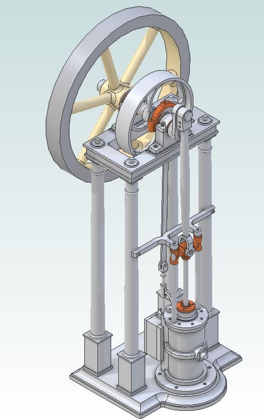
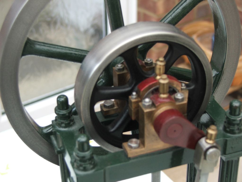
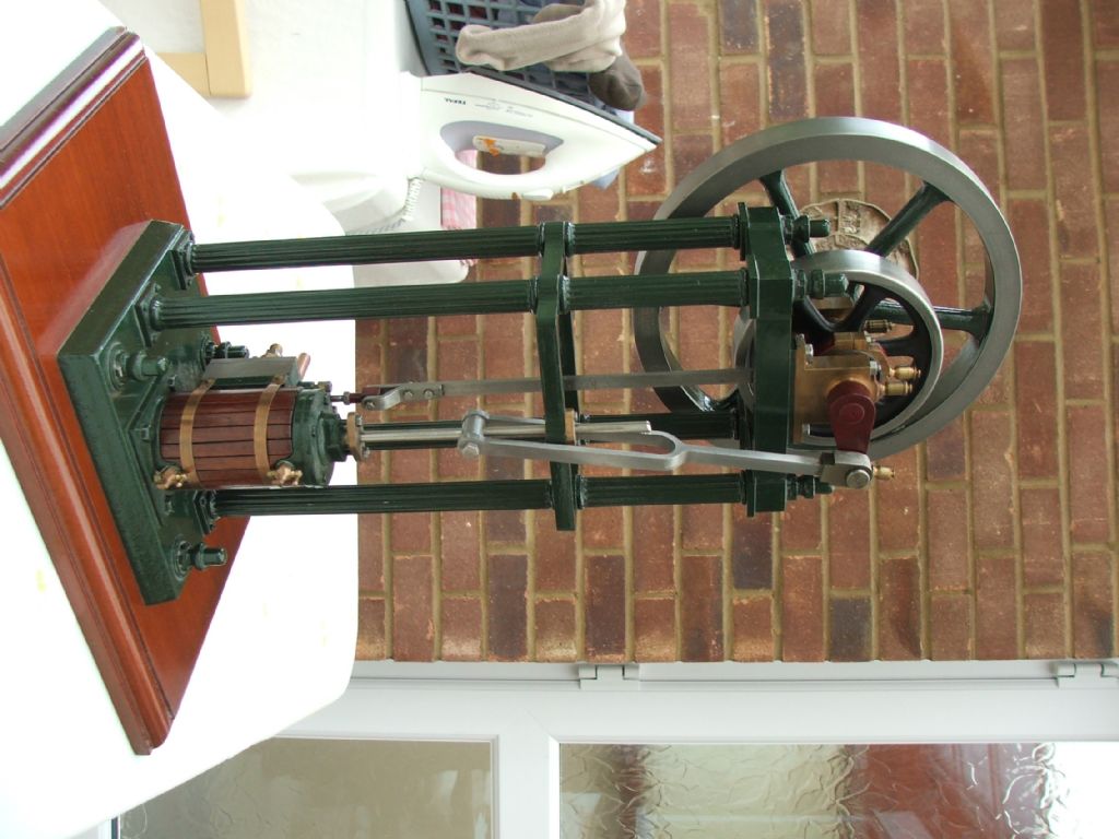
      While making the Stuart Victoria last year I started to feel like I would also like to make the Real to go with it. So I bought Andrew Smith's book (cheapest source of drawings) on building the Real and started to look a pictures of them on the net, the more I looked the more I saw that I did not like and that included what Stuarts are asking for the kit. So over a few winter evenings I developed a different version that has gone by the working tile "Unreal" which addresses some of these issues and also more closely follows the etching from Andrew's book that was his inspiration.

      Although I could have made the flywheel and cylinder from scratch I decided to use just these two Stuart castings as I felt that others who may want to follow suit would find these the most difficult parts to make from scratch. I also went for a metric design based on nominal sizes rather than direct conversion of the old imperial sizes again with many beginners now of an age where they were taught metric at school that make sense and if using handwheels on modern metric machine sit is easier to keep track of whole metric numbers rather than working to several significant figure after the decimal point. This results in a model with 25mm bore and 50mm stroke

      I'll go into more detail during the build about the various modifications but a summary is as follows

      Base – This is a very expensive casting at £45 for what is little more than a rectangle with tapered sides and rounded corners So something with a bit more shape and detail
      Columns – Again something with more shape and detail than the plain tapered ones
      Entablature – This is shaped the wrong way for any form of classic architecture being larger at the bottom than the top all for the sake of easy removal from the sand so that needs to be corrected and some additional detail added at the same time
      Pulley – change for one closer to the one shown in Andrew's book not the standard Stuart one used on all their 2 x 1 models
      Flywheel – remove the "lumps" they now cast on the rim, add some counterbalance weight and fit with a gib head key
      Valve/eccentric – modify layout to do away with the dog legged valve rod and make an eccentric correctly shaped for vertical use
      Cylinder – move exhaust position as it gets a bit tight between column and exhaust position
      Crosshead and guides – change to rod guides which was another feature of the engraving in Andrews Book.
      Conrod – change from the tuning fork design to one similar to the other 2 x 1 Stuarts and Andrew's etchings

      On the cost front this model work out at about £200 which is half of what Stuarts are currently asking. This is based on buying most materials by the 300mm length so you will have some over for the next engine. Larger diameters by the 25mm length where available. The cost also includes enough for fixings etc as well as the price of the two castings.

      A few more bits of tooling and cutters may be needed but those will last a long time and if used over several more models will not amount to much. I did make use of my CNC for some of the parts but just about all could be done with manual machines and only one part would need a bit more of a redesign to make it a bit easier to cut from solid.

      Next time I'll start on the construction of the base. And don't worry as unlike the Wall engine this one is finished and runs very well so there will be a happy ending to the build.

      Advert
      #3493
      JasonB
      Moderator
        @jasonb

        A revised design for the Stuart Real

        #598826
        PatJ
        Participant
          @patj87806

          That engine looks really nice with that center pully ? with the curved spokes.

          Gives the engine a very refined look, as does the base.

          I don't think I have ever seen an arrangement like that.

          And nice 3D work !!

          .

          #598835
          Nigel Graham 2
          Participant
            @nigelgraham2

            A very elegant machine!

            It is an unusual layout – a true vertical. (The more common ones with the crankshaft at the bottom, marine-engine style, as more properly of "inverted-vertical" layout.)

            As finishing touches the pulley (not flywheel) would have been very slightly crowned – though that is probably barely noticeable at that scale – and it may be worth examining your source engraving to see if it had square or hexagonal nuts, especially in the larger diameters.

            Curved spokes were common practice on cast-iron pulleys etc, not for looks but to absorb the contraction stresses in cooling.

            #598836
            blowlamp
            Participant
              @blowlamp

              Jason. Did you draw that in TurboCAD? devil

              #598845
              JasonB
              Moderator
                @jasonb

                I don't think I would have got passed the design stage let alone making it if I had used Turdbocad!

                Yes the pully has some crown to keep the belt tracking true and Andrew's engraving has hex fixings which I also used and although metric I did not use run of the mill mass produced ISO nuts they are all smaller hex, taller and only chamfered one side to more closely resemble earlier nuts.

                #598863
                blowlamp
                Participant
                  @blowlamp
                  Posted by JasonB on 22/05/2022 07:32:33:

                  I don't think I would have got passed the design stage let alone making it if I had used Turdbocad!

                  Yes the pully has some crown to keep the belt tracking true and Andrew's engraving has hex fixings which I also used and although metric I did not use run of the mill mass produced ISO nuts they are all smaller hex, taller and only chamfered one side to more closely resemble earlier nuts.

                  It's looking good. Nice attention to detail. yes

                  Martin.

                  #598867
                  SillyOldDuffer
                  Moderator
                    @sillyoldduffer

                    I like the look of it, but wonder how practical the configuration would be in full size? Compared with a horizontal engine, the centre of gravity is high. And not only do the four spindly pillars carry a heavy flywheel and loaded belt pulley but the crank waggles from side to side, alternating the load. I'd expect the configuration to vibrate and limit the power take-off. Saves lots of floor space, but could that be better done by inverting the engine, cylinder at the top, and the heavy moving bits underneath?

                    Can Jason's CAD tool can tell him where the centre of gravity is on this fine looking engine and how much it moves about as the engine turns? Bet it can!

                    smiley

                    Dave

                    #598868
                    JasonB
                    Moderator
                      @jasonb

                      You'll just have to wait for the video at the end and watch it slowly and smoothly ticking over at 35rpm, even when I wind the wick up it sits nice and solid smile p Ctr of mass is actually about half way up the guide bars though I have not set the material density for each part so it could move slightly if I did.

                      Many of these engine actually only had two columns with the other end of the crankshaft running in a bearing block supported by the wall of the workshop or engine room. Also a lot easier to assemble an engine with the heavy cylinder at the bottom when all you had was block and tackle and it gives a short belt run to any overhead line shafting.

                      #598869
                      derek hall 1
                      Participant
                        @derekhall1

                        I built the "Real" from Stuart Turners castings and to the design by Andrew Smith around 40 years ago. It was my first engine built with castings and I think the whole lot cost £20.

                        I recently checked the prices for castings for this engine and thankfully was sitting down at the time. All apart from the cylinder and flywheel can be made from the solid.

                        Agree that Jason's version is aesthetically much better looking

                        Regards

                        Derek

                        #598892
                        SillyOldDuffer
                        Moderator
                          @sillyoldduffer

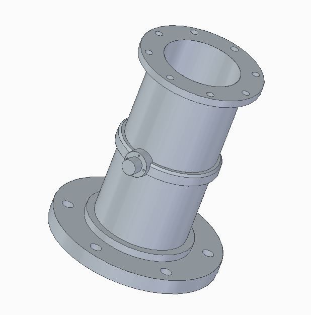
                          Don't like to complain, but Jason's engine is an obvious copy of my Cotton Reel!

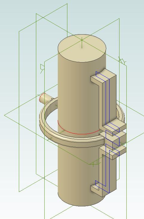
                          jbcylinder.jpg

                          Knew I should have applied for a patent…

                          devil

                          #598893
                          JasonB
                          Moderator
                            @jasonb

                            Well I suppose it's worth 3/10 for a half hearted effort, you have left all the tricky bits off.smile p

                            cylinder.jpg

                            #598897
                            duncan webster 1
                            Participant
                              @duncanwebster1

                              Cylinder on the floor crankshaft up in the air was quite common, the next step up from beam engines. There is a twin cylinder one in Bolton steam museum (nmes.org). For fellow pedants, cylinder up in the air and crank on the floor is correctly called an inverted vertical, but I suspect this has gone by the wayside.

                              Edited By duncan webster on 22/05/2022 20:56:48

                              #598923
                              JasonB
                              Moderator
                                @jasonb

                                And that is why Andrew Smith gave the model this name because it is a "real" or true vertical and one with the cylinder at the top is an inverted

                                #598926
                                SillyOldDuffer
                                Moderator
                                  @sillyoldduffer
                                  Posted by JasonB on 22/05/2022 20:14:40:

                                  Well I suppose it's worth 3/10 for a half hearted effort, you have left all the tricky bits off.smile p

                                  cylinder.jpg

                                  I get into trouble when I tackle the tricky bits! Avoided unless they can be fixed with paint and putty.

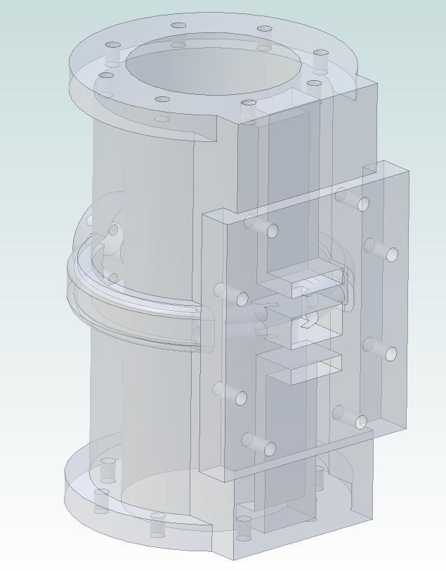
                                  The rear view transparency confirms an interesting detail: the exhaust is carried around the cylinder to the boss-thingy on the front, which would keep the cylinder hot. As the hollow band is more complicated to make than a steam jacket, I wonder if the idea was to concentrate heat at the cool point in the middle where the piston spends most of its time. I often focus on the quaint look of early engines without noticing the design is technically clever too.

                                  How would a hollow band around a cylinder be cast?

                                  Dave

                                  #598979
                                  JasonB
                                  Moderator
                                    @jasonb

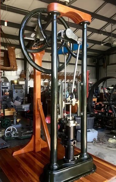
                                    I don't think the wrap around exhaust would have done a great deal in teh way of cylinder heating a sthe area in contact with teh cylinder wall is quite small, mor ejust a way of getting the exhaust connection to where it was wanted. As can be seen on this full size engine the heating would be minimal

                                    2 column workshop engine.jpg

                                    As for how the part would have been cast that would have been done with an extra cor. As well as the main core forming the rough bore and the two dog legged ones for the inlets the stubby one for the exhaust port would have been extended around the cylinder and supported at the other side by a spigot which would have made the boss hollow and have been located in a suitable core print on the pattern.

                                    cylinder core.jpg

                                    To convert the Stuart side exhaust to the front exhaust needs a cunning planwink

                                    #598997
                                    JasonB
                                    Moderator
                                      @jasonb

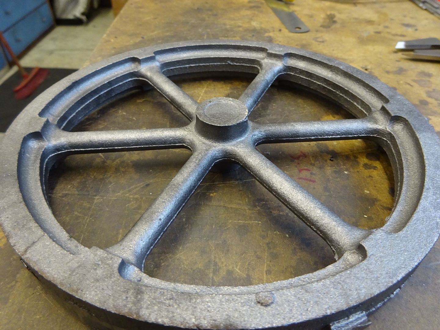
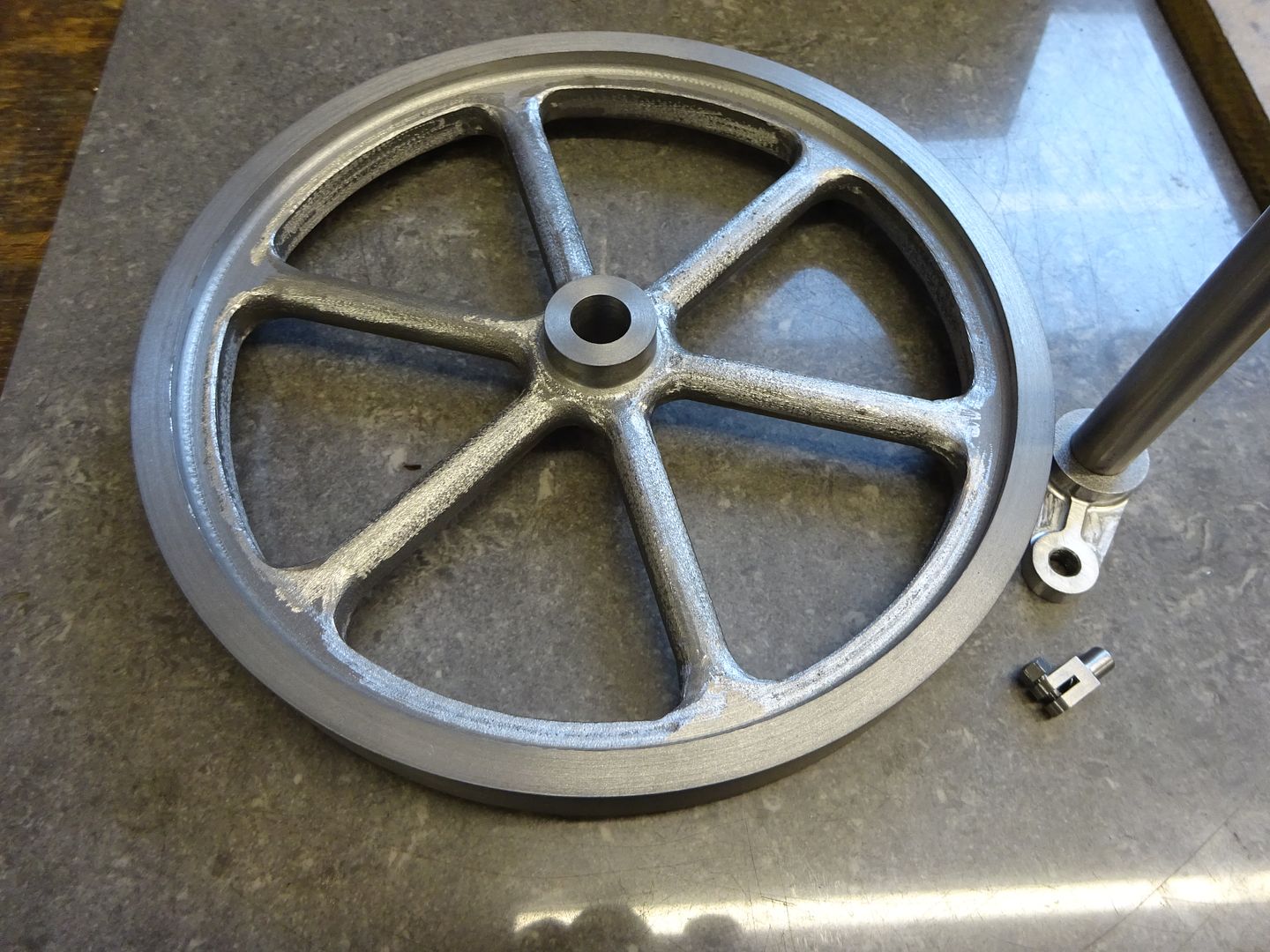
                                      I decided to make a start with the flywheel while I was waiting for a delivery of materials that would have allowed my to start with the more logical base. You seem to read a lot that the current Stuart castings are not what they used to be but I have to say that both the flywheel and cylinder castings were very good – No holes, no hard spots, mould halves lined up with no step and very little flash. The only real downside is that Stuarts seem to only supply castings from the pattern used for the twin Victoria which have the ugly bosses cast in where two flywheels are bolted together.

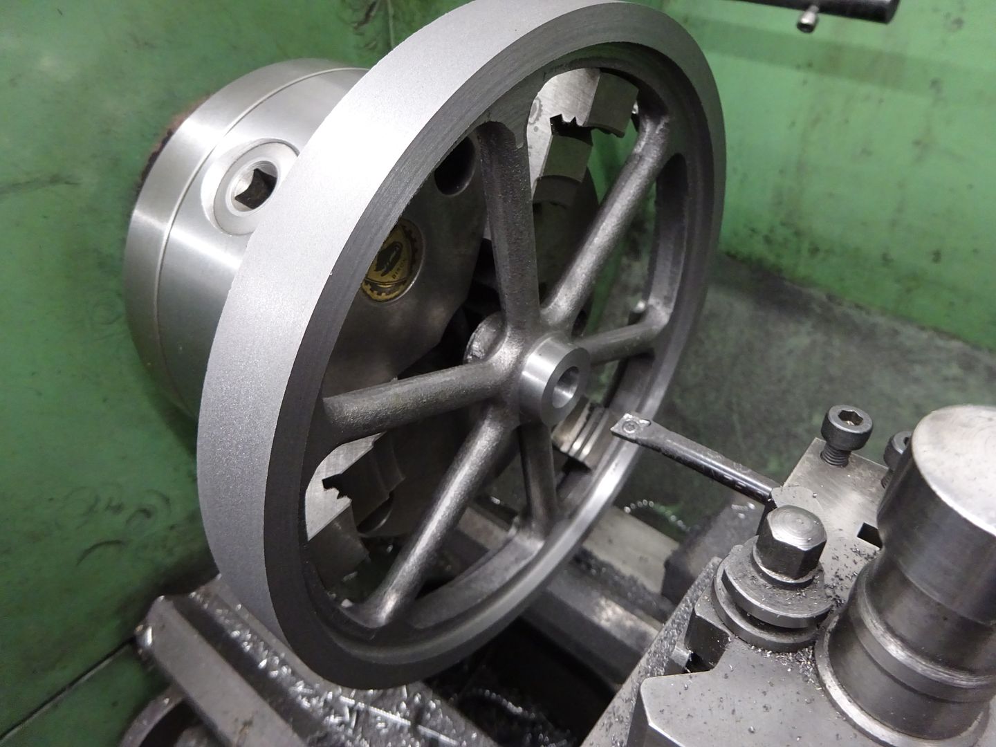
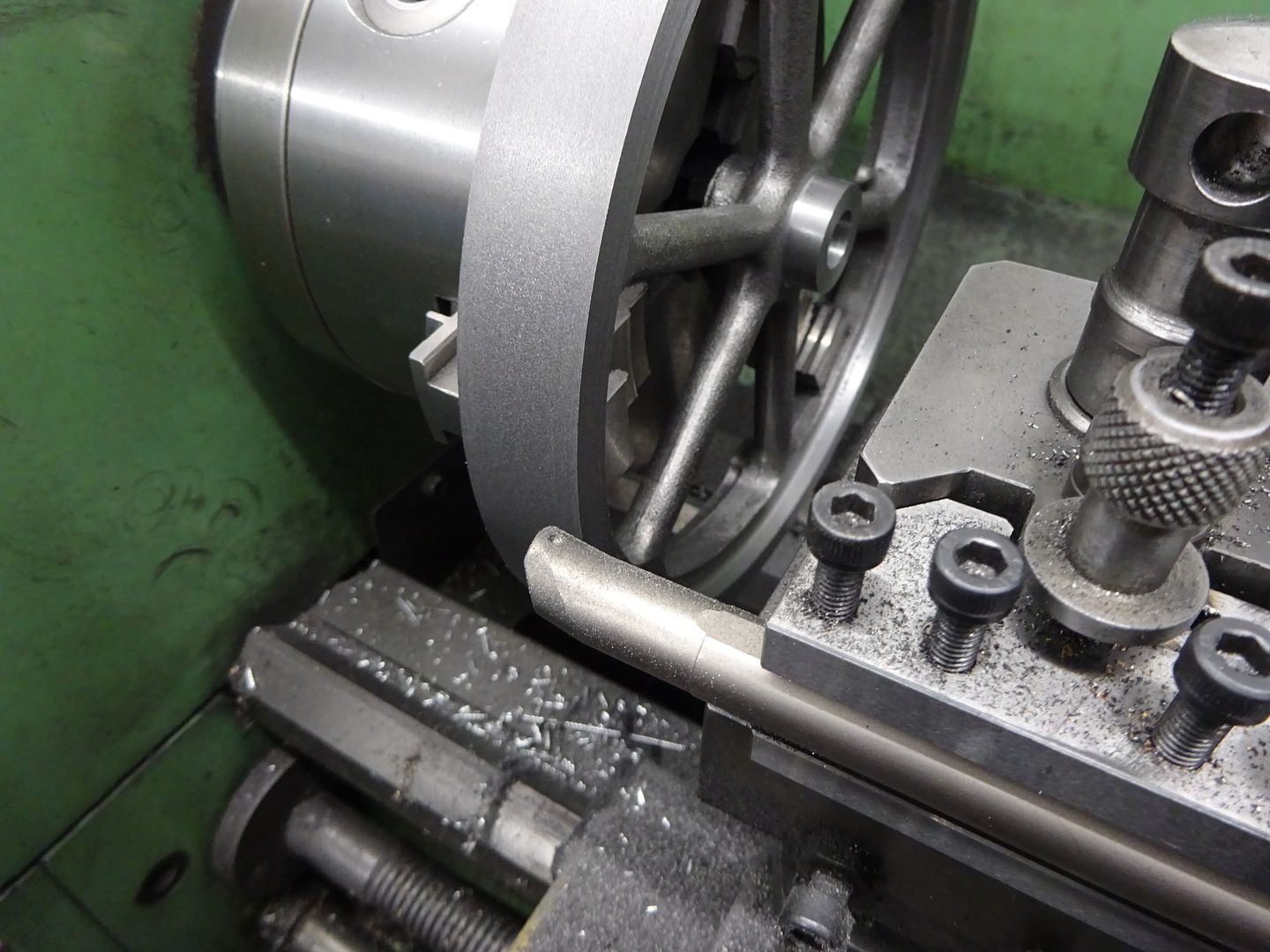
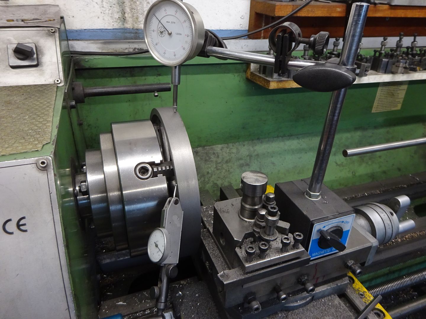
                                      I like to fettle my castings before machining so there is no risk of spoiling any finished surface if you slip with a file or grinder so that was the first thing to do. As the inner rim is not machined I like to set that to run true and was able to do so by holding in the 3-jaw. This allowed me to turn the outer surface, one side, clean up the hub and also bore the hole all at one setting. I like to bore the hole to finished size as a reamer is likely to follow a drill hole that may have wandered and I can also get a slightly closer fit than a typical reamer will give which reduces the chance of a wonky flywheel. Once I got close to size by measuring with the digital callipers I switched to using a piece of the crankshaft material as a plug gauge to get the final size.

                                      I did the outside with the lathe running in reverse and used a boring bar mounted upside down which easily reached around the casting with minimal overhang

                                      I then changed to the 4-jaw and set the machined surfaces to run true using one indicator on the OD and another against the side.

                                      It was then a simple job to turn the other face and clean up the hub.

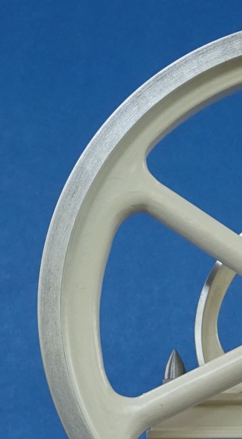
                                      You can see where I have turned away the bosses that there are some flattish areas these were blended in with a Dremel using an oval shaped grinding point.

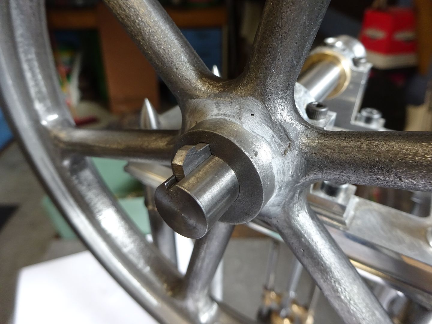
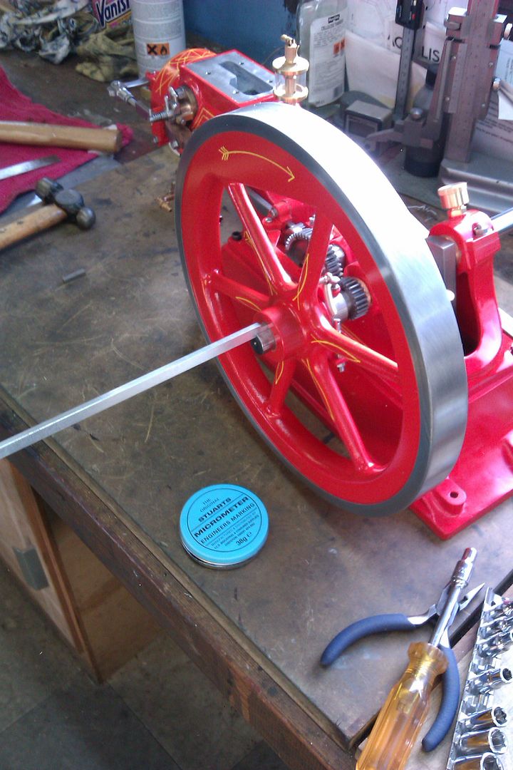
                                      Stuart show a grub screw to retain the flywheel but I used a broach to cut a tapered keyway and machined up a suitable gib head key from gauge plate to fit.

                                      Jumping ahead to when I test ran the engine it was quite noticeable when running slowly with no load that the engine rotated faster when the crank was moving downwards than up which is due to the added weight of the conrod, crosshead, piston and piston rod all pulling downwards and then the engine having to work harder to lift that weight back up again. So some strips of lead flashing were cut and bent to the curve of the inner flywheel and held in place with masking take to experiment with how much counterweight needed to be added. Once happy the two layers of Code 4 lead were bonded in place with JBWeld. Once hardened the excess JBW was cleaned up, a bit more U-Pol filler added to blend things in and you would think it was all part of the casting.

                                      #599165
                                      Weary
                                      Participant
                                        @weary

                                        Jason,

                                        Very nice work!

                                        But, can you perhaps give a little more detail as to how you "used a broach to cut a tapered keyway" sometime please? Was it a home-made or commercial broach, and how did you achieve the required taper?  

                                        Thanks & regards,

                                        Phil

                                        Edited By Weary on 25/05/2022 08:53:26

                                        #599224
                                        JasonB
                                        Moderator
                                          @jasonb

                                          It was a commercial broach but I made my own bush for it with the required taper. These are quite simple to make – just a top hat shape to fit the bore and long enough to support the broach for at least the full depth of the hole. After turning the bush is held in the mill vice at the required angle 1:100 for metric and 1:96 for imperial which is about 1.75degrees and a suitable slot cut into the bush. I've built up quite a few over time of different diameters an plain or tapered The one laying down on it's own is the one I made for this job.

                                          20220525_164841[1].jpg

                                          The key I either cut from gauge plate or rectangular section key steel if I have it, again setting to the angle and milling the face that will touch the flywheel. They are then blued and fitted using a fine but sharp file, I find if the stock is left long it gives you a bit more to get hold of when you need to remove the key to see where metal needs to be removed.

                                          #599415
                                          JasonB
                                          Moderator
                                            @jasonb

                                            As I had cut off a bit of 12mm PGMS to use as a plug gauge for the flywheel hole I thought I may as well work on the crankshaft next.

                                            Starting with a piece of the 20mm square bar I had bought for the column bases it was machined down to an oversize rectangular section and then thinned further at the pin end followed by reaming the holes for the shaft and pin.

                                            I could then use the hole to gauge the fit of the reduced diameter at the end of the crankshaft

                                            The crank can then be shaped in a number of ways from simple buttons and filing, to using the rotary table or the CNC if you have one. I opted for the last and used a 4mm dia cutter with a 1mm convex corner radius so it left a nice fillet on the internal corners.

                                            With that machining done the crank was Loctited (648) onto the shaft and set aside to cure. Hold the shaft to run as true as you can in a collet, 4-jaw or good 3-jaw and then skim the crank to finished thickness. This ensures the face that the crank pin will be tightened against is at right angles to the crankshaft's axis and therefore the pin should end up parallel to that when fitted.

                                            I'll come back to the pin later once the conrod bush is turned and fitted so it can be used to gauge the fit.

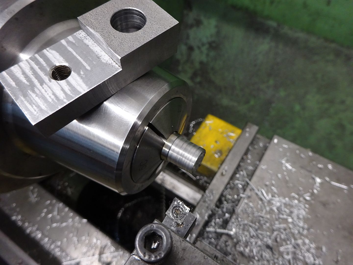
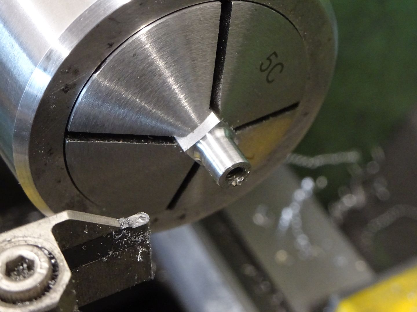
                                            While I had a bit of time to spare a small part was ticked off the list in the form of the valve rod clevis. I often mill my on small square, hex and rectangular components from round stock a sit's often not worth buying a 300mm length of a size you won't use much plus some small square stock is not that crisp and often comes with rounded corners. After milling the Slot was formed with a 1.5mm slitting saw then the part was cut off the parent bar. I used a square collet but the 4-jaw will do to hold while the end was turned, drilled and tapped, I'm using a 2mm radius tool which like the milling cutter mentioned above leaves a pleasing small internal fillet.

                                            #599680
                                            JasonB
                                            Moderator
                                              @jasonb

                                              With the arrival of some additional material the build can now follow a more logical direction starting with the base.

                                              As I said in the introduction the one supplied by Stuarts is little more than a rectangle with rounded corners and a bit of draft angle which only needs flattening on the bottom, skim cut off the top and a few holes added which does not give you much workshop time for your money as it should not take more than an hour to do.

                                              I opted for aluminium as it's easy to cut and no more expensive than bright steel flat. I've not noticed any problems with my other models that use aluminium right from the early ones I made 30+ years ago like the Minnie which has several aluminium castings through to others with aluminium castings and the ones I have fabricated using the material. Even Stuarts have used it to cast the fluted column of the Williamson.

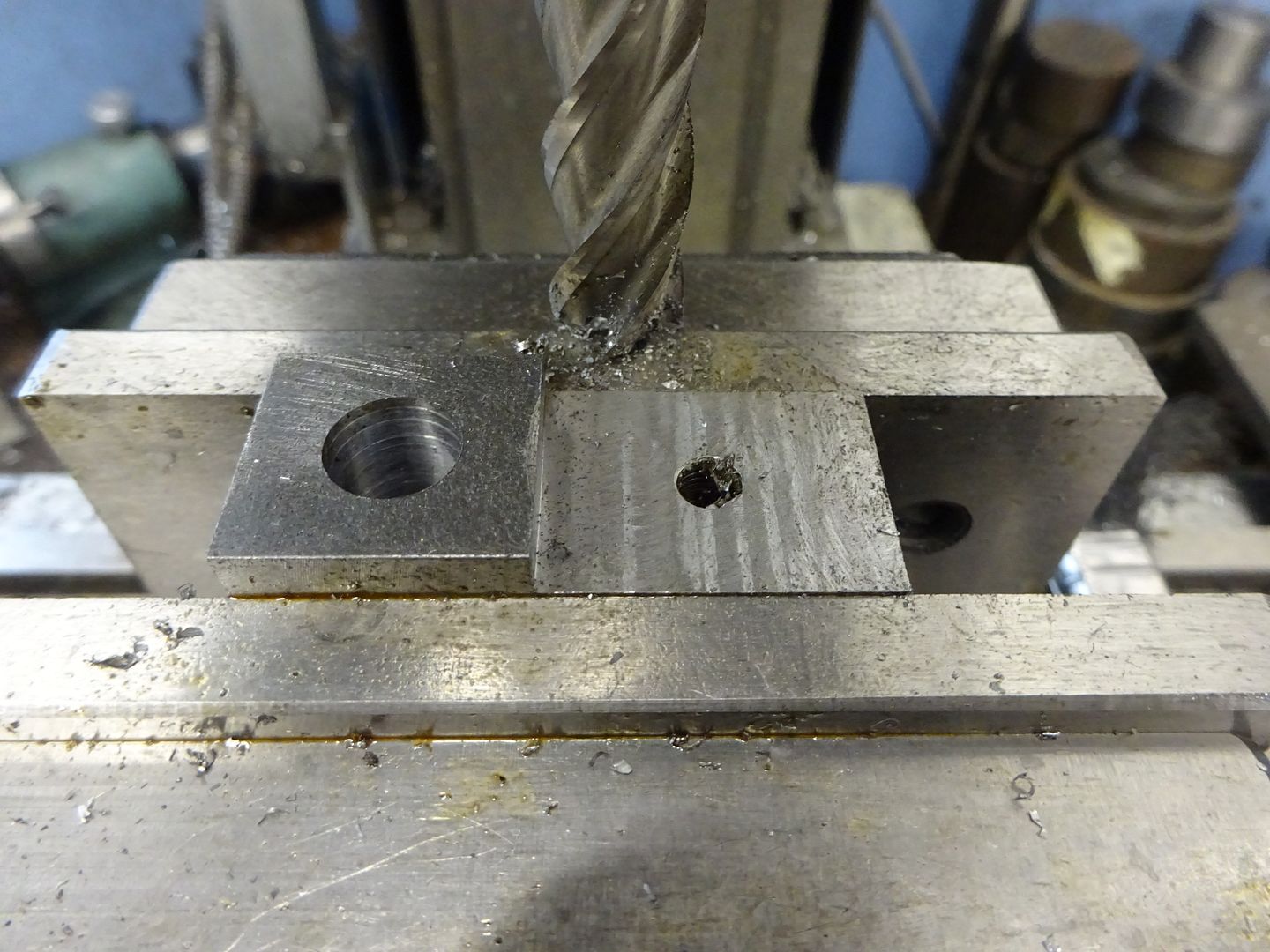
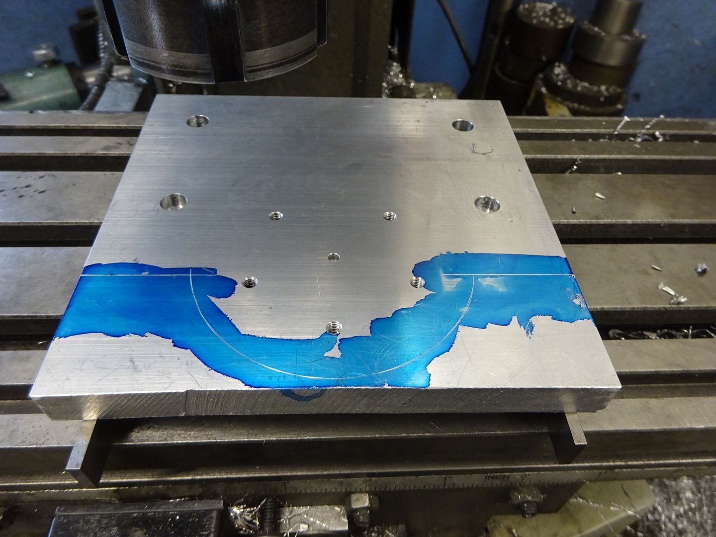
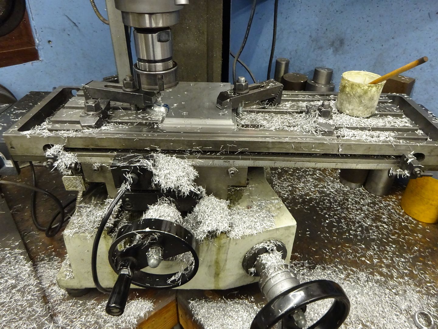
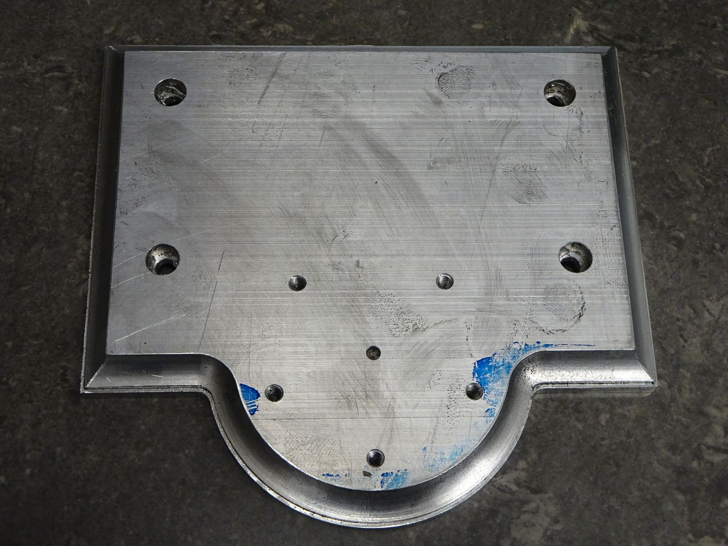
                                              So starting with a piece of 12mm material it was sawn slightly oversize and clamped to the mill table on some packing so that three sides could be milled square to each other. I then drilled four hole 5mm which were later countersunk on the underside for M5 CSK socket screws. These holes were also counterbored from above by plunging with an 8mm 3-flute cutter to form sockets that spigots on the column bases will fit tightly into so they locate accurately. I also drilled and tapped M4 for the studs that will hold the cylinder cover in place and at the same time added a small hole to use as a datum at the ctr of the cylinder position that could be used to locate the base on the rotary table if using that to mill the half round.

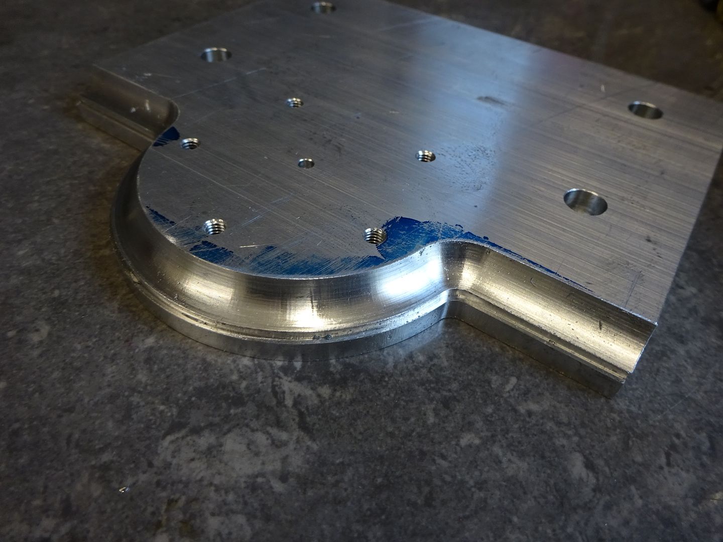
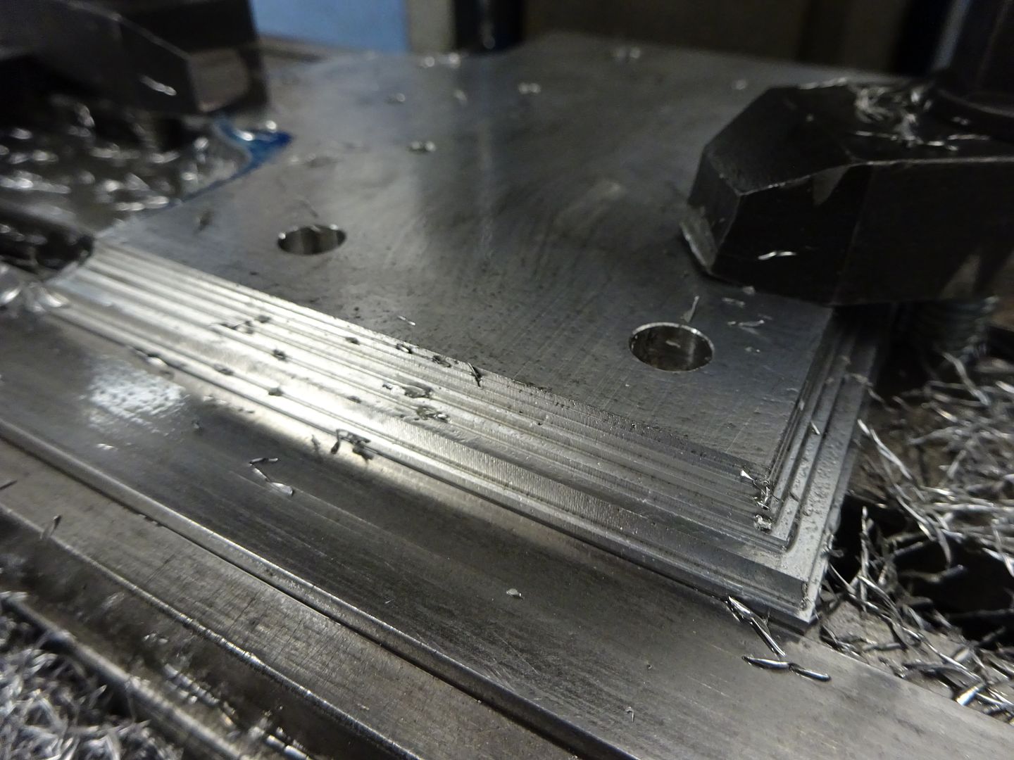
                                              The two areas of waste were hacksawn off and put aside as they can be used for other parts later on then the front face with it's half round was milled to size and the decorative moulding added firstly by cutting a rebate 10mm deep and then using a 12mm ball nose cutter to do the concave detail.

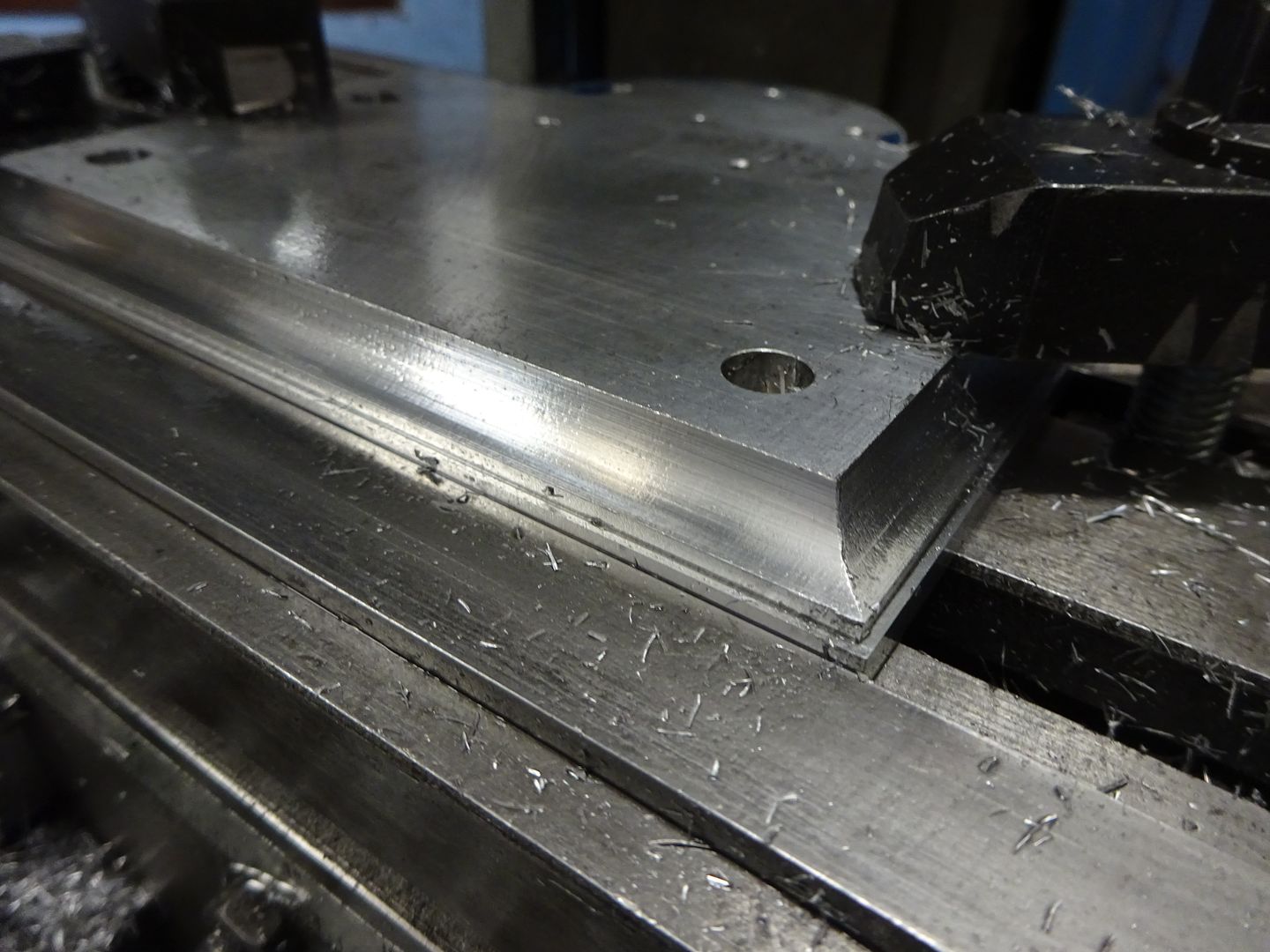
                                              The straight sides were next, to make it easier I clamped a straight edge to the mill table and clocked it in so it was then an easy job to locate each side against this and machine at the same settings. First doing the rebate and removing some of the waste with the same straight 10mm cutter.

                                              Then the concave with the 12mm ball ended one

                                              You can always judge if you have had a productive session in the workshop by the size of the pile of swarf produced.

                                              The completed base which to my eye has a much more interesting overall shape and the moulded edge looks a lot nicer than the rather plain original. Plus with materials at 1/4 the cost of the casting and a bit more time needed to machine you are getting better hours enjoyment per £ smiley

                                              Edited By JasonB on 28/05/2022 17:05:50

                                              #599726
                                              Baz
                                              Participant
                                                @baz89810

                                                Certainly a much nicer looking base than the Stuart original one.

                                                #599802
                                                paul rushmer
                                                Participant
                                                  @paulrushmer83015

                                                  Real engineReal engineHi Jason

                                                  Thought you mite like to see my fathers take on the real. Fluted columns redesigned piston rod support acorn nuts and a large pulley, he wanted to fit a govener but that never got done.

                                                  Paul

                                                  l

                                                  #599803
                                                  paul rushmer
                                                  Participant
                                                    @paulrushmer83015

                                                    Real engine

                                                    Edited By JasonB on 29/05/2022 14:07:18

                                                    #599834
                                                    JasonB
                                                    Moderator
                                                      @jasonb

                                                      That looks good Paul and a few other small changes I can spot that were made too.

                                                    Viewing 25 posts - 1 through 25 (of 45 total)
                                                    • Please log in to reply to this topic. Registering is free and easy using the links on the menu at the top of this page.

                                                    Advert

                                                    Latest Replies

                                                    Home Forums Stationary engines Topics

                                                    Viewing 25 topics - 1 through 25 (of 25 total)
                                                    Viewing 25 topics - 1 through 25 (of 25 total)

                                                    View full reply list.

                                                    Advert

                                                    Newsletter Sign-up