Reinventing Jason’s Reinvented Real

Advert

Reinventing Jason’s Reinvented Real

Home Forums CAD – Technical drawing & design Reinventing Jason’s Reinvented Real

Viewing 15 posts - 26 through 40 (of 40 total)
  • Author
    Posts
  • #599675
    SillyOldDuffer
    Moderator
      @sillyoldduffer
      Posted by Tim Stevens on 28/05/2022 12:23:12:

      Can I suggest that mathematics has always been there, and mankind discovered it, played about with it, invented devices to use it, and continues to do so? But, we did not invent it.

      Cheers, Tim

      Gosh, too deep for me! I know what you mean, but what are zero, decimal points, the square root of -1 and algorithms? As none of them exist in nature, I think they must be inventions.

      It'll give me something to think about whilst doing my next job. Filing slots is so tedious  worrying about this will keep me awake!

      Dave


      Edited By SillyOldDuffer on 28/05/2022 16:21:05

      Advert
      #599687
      Tim Stevens
      Participant
        @timstevens64731

        Not wishing to divert the thread, but … all I'm suggesting is that mathematics, the idea that two and three make five, and four times four is sixteen, etc (an exceedingly big etc) wass true before manking came along with his slide rule and his logarithms, and his decimal system, and his square roots, all of which are inventions based on the bare facts of numbers and how they relate.

        Not deep at all – although various of the tricks have been labelled as magic, the work of the devil, and other names from the world of fairy stories. Mostly because of ignorance – but that is no excuse to promote such ideas.

        Next week – is Sudoku anything to do with mathematics … ?

        Cheers, Tim

        #599689
        Baz
        Participant
          @baz89810

          No Sudoku is just filling in missing numbers in rows and columns, isn’t it?

          #599767
          SillyOldDuffer
          Moderator
            @sillyoldduffer

            Please don't tempt me with Sudoku – I waste enough time as it is!

            More progress with Soiid Edge and the model:

            • added a guide for the valve rod using 'Create Part in Place', which is a very helpful technique allowing new parts to be defined on an Assembly. No need to remember things like flange diameters, PCDs, and bolt hole positions. I don't think Fusion has it and FreeCAD certainly doesn't.
            • used 'Create Part in Place' to add and position the D slide inside the valve box so the eccentric movements open and close the ports correctly.
            • added a steam input to the valve box and two pipe runs for steam feed and exhaust. Pipe runs travel awkwardly around and inside the model and can be a lot of work to define in 2D. Solid Edge's 3D sketch tool simplifies the job. (After how it works is understood!)

            jbclobega6.jpg

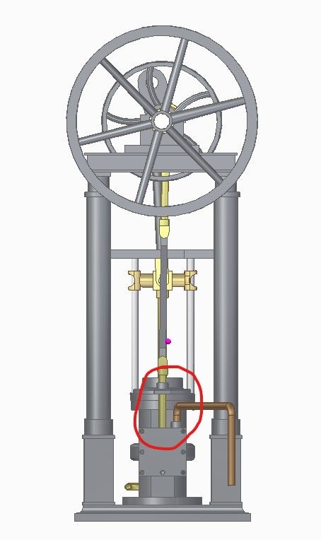
            Then inspected the model for faults, missing features, improvements and misalignments.

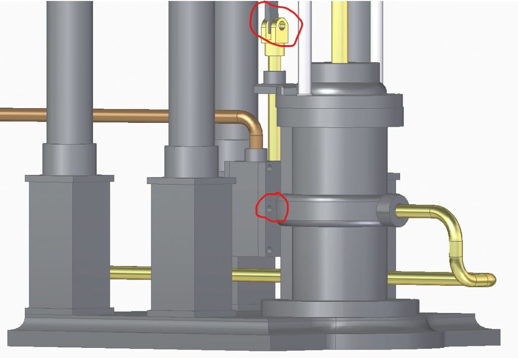
            jbclonecylvalvefaults.jpg

            Found a few, ringed in red:

            • Bolt hole forgotten in the valve-box cover. (Unlike the other cover holes this one can't be drilled through because it would cut the valve-rod. I meant to come back to making a shallow hole and didn't.)
            • A small problem is with the middle cover holes in the valve-box. They emerge on the cylinder side close to the exhaust belt, which would make assembly of the real model a little inconvenient. I'll probably leave it!
            • The strap connecting the valve rod to the eccentric is misaligned because I got the bend angle slightly wrong. This can be corrected when I make a planned change and take the strap much closer to the eccentric hoop.

            Now I've cracked pipes a new trip will be adding a throttle valve. As PatJ said, this stuff is addictive…

            Dave

            #599771
            JasonB
            Moderator
              @jasonb

              Dave you should not need to worry about that central pair of valve chest holes, studs would have been screwed into then from the valve side so no need to get to the back of them. A little more thickness to the port face would not go amiss then the studs can go into blind holes.

              Your six holes are rather close to the edge/corners.

              I was in two minds whether to add a valve to mine but did not in the end as I would have just left it open anyway and used my manifold to control air flow

              #599789
              SillyOldDuffer
              Moderator
                @sillyoldduffer

                Thanks Jason.

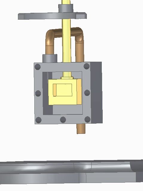
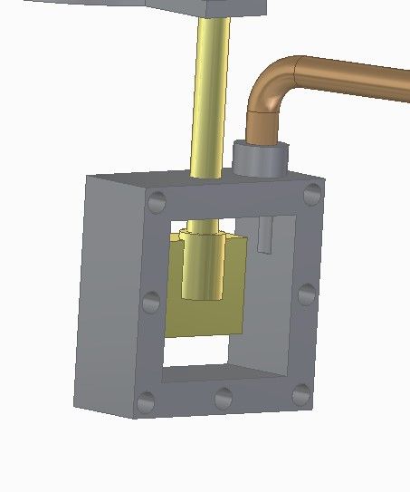
                Looking at the too close holes got me worrying about the D-slide valve. May I pick your brains on that too please?

                From the front:

                dvalvecylinderside.jpg

                Rear:

                jbclonedsliderear.jpg

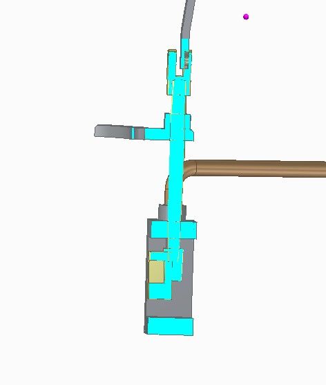
                Section:

                jbclonedvalvesection.jpg

                So, there's nothing holding the slide valve flat against the face apart from steam pressure and the valve rod. One way of fixing it would be to extend the back of the valve so it rubs against the cover, which is more weight and friction, Therefore I'm wondering about putting a couple of rounded end screw adjusters through the back of the rear cover that could be tweaked to press the slide against the port face. Works mechanically, but liable to leak I feel. How is yours done?

                And worrying about leaks, I've noticed there's no stuffing box on the valve rod or cylinder top! Back to the drawing board!

                Ta,

                Dave


                Edited By SillyOldDuffer on 29/05/2022 11:50:09

                #599797
                JasonB
                Moderator
                  @jasonb

                  Generally you don't need to hold the valve against the portface, as you say steam does that. Some designs have a small flat bronze spring but the majority have nothing.

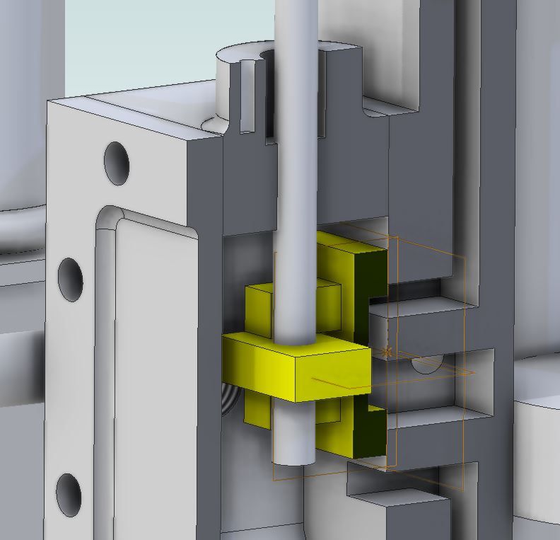
                  What you do need is an allowance for the valve to lift off the port face should you get a build up of condensate in the cylinder then the valve will lift and let it out. On a lot of models the valve has a slot for a rectangular nut, the slot being a bit deeper than the nut. here's a section through the engine with nut and Valve rod not sectioned, you should be able to make out that the nut does not touch the back of thevalve

                  valve section.jpg

                  #599812
                  SillyOldDuffer
                  Moderator
                    @sillyoldduffer

                    Thanks Jason. I was in danger of overthinking model slide valves:

                    • friction: how much power is needed to operate a slide valve? Considerable I suspect.
                    • material: cast-iron for low friction.
                    • reduced contact area for low friction versus increased leakage
                    • pressure: what's the effective steam pressure on the valve? (Pressure on the boiler side less exhaust pressure from the cylinder.)
                    • Lead and lap
                    • lubrication

                    Notice my list doesn't include condensation and the need to let the valve lift off! And now condensate has been dropped into the mix, water collecting in the engine is another worry.

                    Your nut makes me realise I've another improvement to make. My design sits the end of the rod precisely in a socket, so both rod and socket have to be machined accurately to length. Better drill all the way through the block and allow the it to be adjusted on the rod.

                    Dave

                    #599820
                    blowlamp
                    Participant
                      @blowlamp

                      Dave.

                      I was intrigued by your awkward pipe run comment, so I thought I'd try something in MoI, just to see what could be done. There is no dedicated tool for pipes, which means having to use a combination of the tools it does have. However, I'm still pleased with what can be done without a lot of messing about.

                      Video below.


                      Martin.


                      Edited By blowlamp on 29/05/2022 16:25:27

                      #599825
                      SillyOldDuffer
                      Moderator
                        @sillyoldduffer

                        Hi Martin,

                        Enjoyed your MOI pipe bendingvideo – I'm not sure Solid Edge can do that. I'll investigate.

                        Two things strike me about MOI. It has high capability and a simple interface. You make it look easy, and compared with Fusion, FreeCAD and SE there are far fewer controls.

                        After exploring MOI's website I think what's missing is Assemblies of multiple parts and ways of managing them. I suspect most hobbyists don't need the complexity that brings, and would be happy to find a straightforward easy to learn tool that did single parts really well. Although MOI doesn't seem to do Assemblies (where parts fit together and be made to move realistically), it does what I call Arrangements, where 'parts' can be positioned relative to each other, but not interrelated. For many purposes that's sufficient.

                        Mustn't prejudge what I find when I try MOI for real. I'm looking forward to trialing MOI when this engine is finished and I've mastered more Solid Edge mysteries,

                        Dave


                        Edited By SillyOldDuffer on 29/05/2022 17:37:38

                        #599833
                        JasonB
                        Moderator
                          @jasonb

                          At the lowish pressures we tend to run our models at particularly just for display and without load then there is very little pressure pushing teh valve onto the port face so friction is minimal

                          Cast iron or bronze are the usual options

                          See above for friction not really being an issue

                          Valve chest will be at or very close to boiler pressure

                          Lead and lap is a subject in itself

                          Lubrication, why mechanical or displacement lubricators are usually places to feed the incoming steam or directly into the valve chest. You can run an engine for quite some time on just a drop of oil

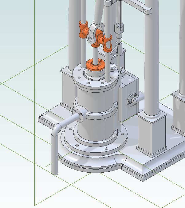
                          There may be a bit of over thinking on the exhaust pipe which seems to be infectious, the reason for bringing the outlet round to the front was for a clean pipe run that would not clutter the engine. A full size one with a similar outlet would most likely just turn the pipe down and into a recess in the floor which would have been covered with some CI chequer plates or grids.

                          Quite like how MOI lets you sketch in all 3 planes but wonder if it would not have been possible just to draw a circle at the end of the "path and "sweep" the profile along it, that is how I did this one though only in two planes

                          unreal pipe.jpg

                          #599839
                          Nick Wheeler
                          Participant
                            @nickwheeler

                            In Fusion Design in place is known as Top Down Design.

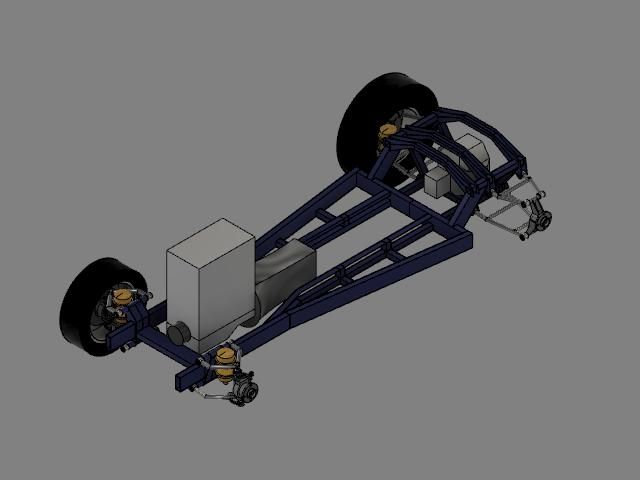
                            Each discrete part(or component) is created in the same file, so your engine, locomotive, chassis, whatever is a complete, but virtual, thing. This chassis, complete with fully articulated suspension is an example:

                            frame.jpg

                            I see no reason to make separate components to import into other files, even if the free version didn't make that slightly trickier.

                            It is much easier to create each new part in the place it's going to fit, referencing the relevant geometry, like a piston in a bore as a simple example. Or the other way around, as you can create the crankshaft, rods, pistons and valve mechanisms first, then build the block/heads etc around them.

                            #599845
                            PatJ
                            Participant
                              @patj87806
                              Posted by Nicholas Wheeler 1 on 29/05/2022 19:01:08:


                              In Fusion Design in place is known as Top Down Design.

                              Each discrete part(or component) is created in the same file, so your engine, locomotive, chassis, whatever is a complete, but virtual, thing. This chassis, complete with fully articulated suspension is an example:

                              I see no reason to make separate components to import into other files, even if the free version didn't make that slightly trickier.

                              It is much easier to create each new part in the place it's going to fit, referencing the relevant geometry, like a piston in a bore as a simple example. Or the other way around, as you can create the crankshaft, rods, pistons and valve mechanisms first, then build the block/heads etc around them.

                              I read about Top-Down design early on, and studied some examples, but I could never get a good enough feel for it to actually be able to use it in a predictable fashion.

                              No doubt it has great merit in the hands of someone skilled enough to know how to use it.

                              One thing that I do that is perhaps similar is that I open the model for a part that is to be mated, and capture the mating face sketch, and then paste the sketch into a new part, and begin the new part with the known geometry.

                              Thus when I go to mate the two parts, I know they will fit because they share the same base sketch.

                              .

                              Edited By PatJ on 29/05/2022 19:58:50

                              #599863
                              blowlamp
                              Participant
                                @blowlamp

                                Dave.

                                That's a fair assessment. There are no constraints or assemblies in MoI, but it is designed to be quick & as easy as possible to use, whilst maintaining a good feature set.

                                What is possible in MoI is to construct an item and then drag, drop, and manipulate it precisely where it is needed very easily.

                                Jason.

                                It's optional to place the profile on the sweep path, but MoI will attempt to auto-position a profile for you, provided it is outside the bounding-box of the sweep path and this is what I did in the video to create the tube. It just saves the step of having to position & align the profile to the path, which could be handy if the path doesn't follow any particular plane.

                                Martin.

                                #599955
                                SillyOldDuffer
                                Moderator
                                  @sillyoldduffer

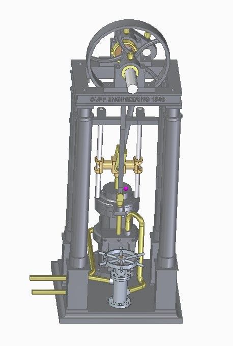
                                  Various fixes and additions: oilers, a throttle, new pipe runs, and embossed lettering on the top.

                                  jbclonega7.jpg

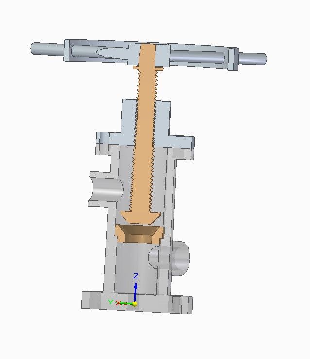
                                  Not sure about the throttle, which is guesswork as the section view shows:

                                  jbclonethrottlesection.jpg

                                  A tapered plug screws down into a matching seat. It should do OK as a stop valve, not convinced it has the fine control of a throttle. The cavity under the seal is purpose made to fill with water! I've also arranged it so steam comes in the top, which means the spindle is under pressure when the engine is off: not good when the gland leaks. I can see at least one other dubious feature.

                                  Got into a few fights with Solid Edge. 3D-CAD is great fun when it works smoothly but frustrating when it suddenly doesn't function as expected and for no obvious reason. Doubly annoying when the reason is found to be me doing it wrong!

                                  Dave

                                  .

                                Viewing 15 posts - 26 through 40 (of 40 total)
                                • Please log in to reply to this topic. Registering is free and easy using the links on the menu at the top of this page.

                                Advert

                                Latest Replies

                                Viewing 25 topics - 1 through 25 (of 25 total)
                                Viewing 25 topics - 1 through 25 (of 25 total)

                                View full reply list.

                                Advert

                                Newsletter Sign-up