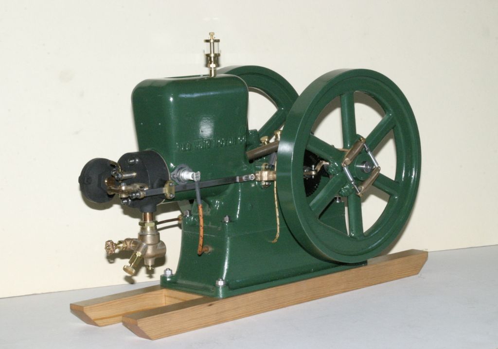
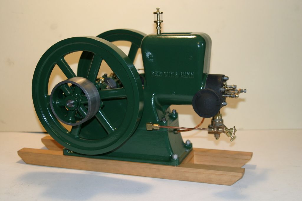
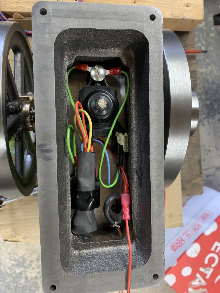
Here's some pictures of my latest project, a Red Wing hit and miss stationary engine. I'm not happy with the paint job or the colour, but that will have to wait till next spring or summer as we are into the windy/rainy season out here (I paint outside). Haven't had a chance to run it yet, it's been raining for the last week. It's got to be my fastest build, started on 12 Jun 21, not much else to do with this pandemic! Now back to the Stuart beam acquired, part built, in the mid "90s.
Ignition is via a Nissan coil (courtesy of my auto mechanic son) hidden in the base. These hi energy coils are used for each individual cylinder, are small (2.5"x1.75"x.75" ), work well on 6 volts and have a built in transistor trigger circuit so when used with points minimal current goes through the points ( new ones aren't cheap though!).
John
Edited By John Purdy on 18/10/2021 18:59:41
Edited to get rid of the closing bracket induced smiley
– I like it too – I struggle with painting, if the weather is warm & dry then there's flies and dust, if there aren't flies & dust then it's too damp and cold..
I am also building a Red Wing, I’m 80% done and I’m looking at doing a similar ignition system using a car plug top coil and I was wondering which Nissan coil you are using.
Looks good. I actually like that colour. A bit of red pinstripe round the flywheel or some such might set it off a bit.
So you run Nissan electronic ignition coil hooked up to points instead of a Hall effect sensor trigger it? I didn't know you could do that. Handy to know.
Ian and Hopper
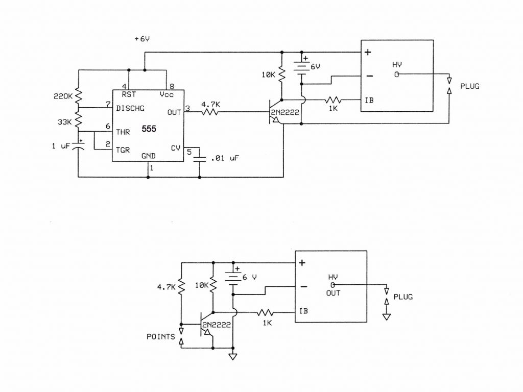
I just talked to my son and he thinks the coil came from a 2004 Nissan Pathfinder. He thinks they are common to a number of models and will check and let me know. I also use one in my Wyvern engine and it runs very well on 6 volts. As I said previously they were expensive, $280 here in Canada, but he says the price has dropped considerably and are now about $57 but should be available from a wreckers for less. Here is how I hook them up (excuse the quality, it's just a shot from my notebook ). As can be seen there are two ways of hooking it up. One where the spark occurs on points closing and one where it occurs on points opening. I used the circuit where the spark occurs on point closing and arranged the timing appropriately. I had to do it this way with the Red Wing as the points are not isolated but one side of the points is connected to the engine frame, hence spark plug ground. I had measured current draw on 6 volts at about 4 amps.
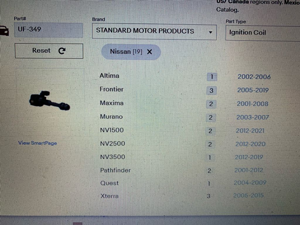
Just got an e-mail from my son, here is the data on the coil. Any of these models with a 3.5L engine uses this coil.
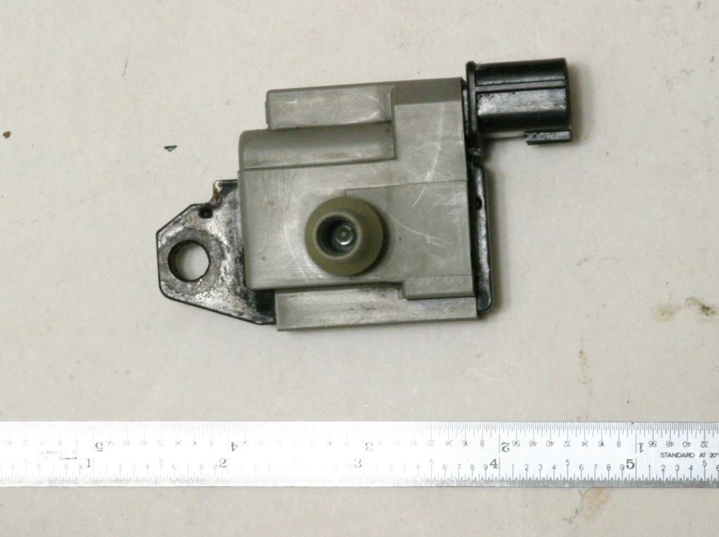
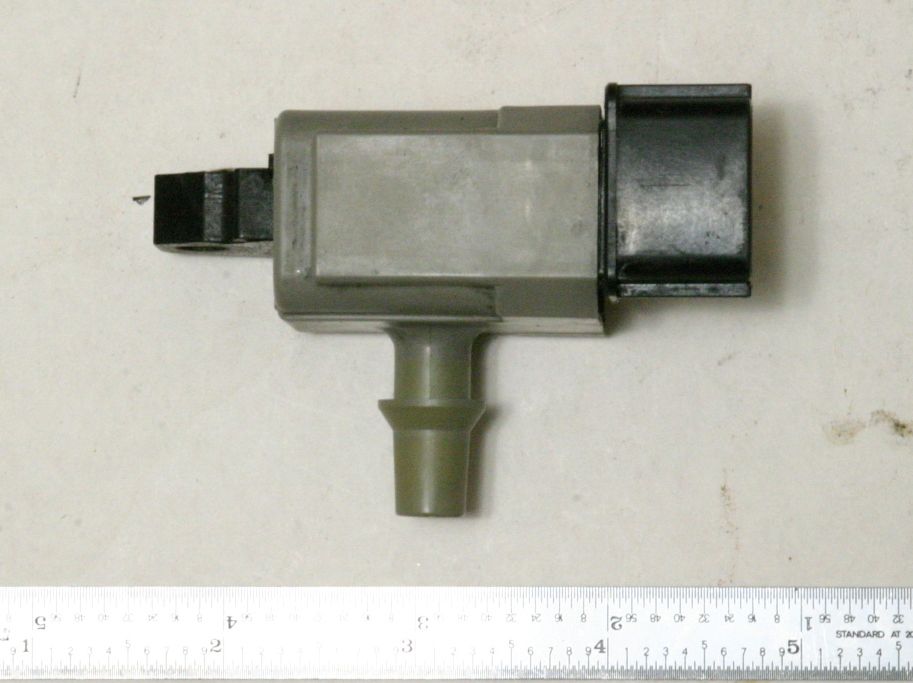
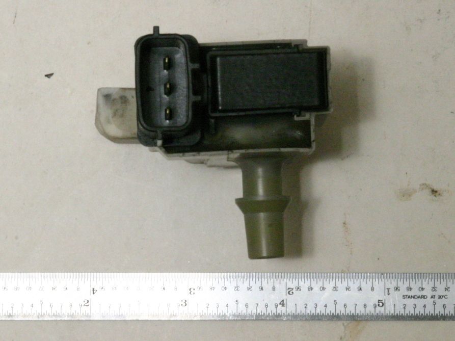
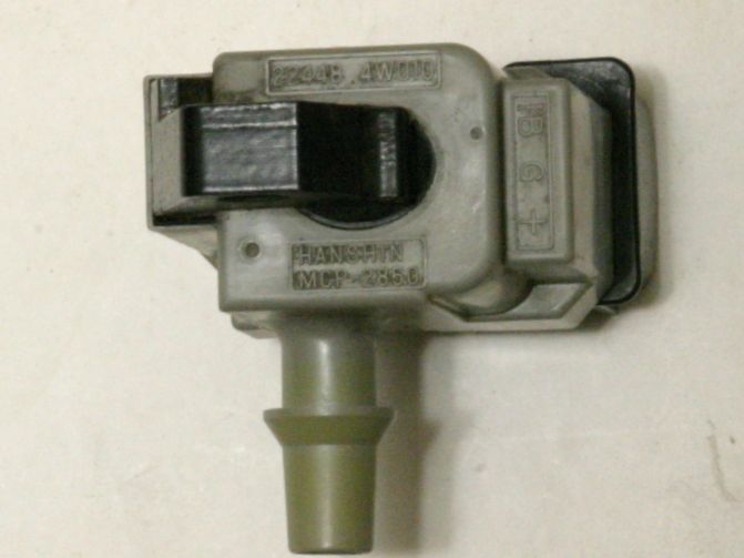
Here are some pictures of the coil. I cut the tower for the plug connection back and solder the ignition wire to the exposed HV connection. The three connection pins accept standard 1/8" quick disconnect push on connectors.
You can see the pins labled IB G + in this last picture as per the schematics above.
If using one and experimenting with it on the bench be very careful as they can produce a lethal voltage especially if run on 12 volts.
The $57 quoted by my son is for an after market coil and that may be his dealer price. I don't know what one from a Nissan dealer would be but I imagine more. So an auto wrecker might be better.
Got a coil today, £28 dealer price and it’s a Lucas! Had a quick test using a 12v battery and works fine with conventional wiring. I’m just waiting for the 1k resistor to test properly.
John you are correct you do get a bit of a belt when messing around 😲
An update on the Red Wing Ignition, I tested the coil just using 12v to the signal pin all ok, then I tried the other method using the 1K resistor……this burnt out the coil, I wasn’t quick enough to disconnect it as I thought the smell was my soldering iron!
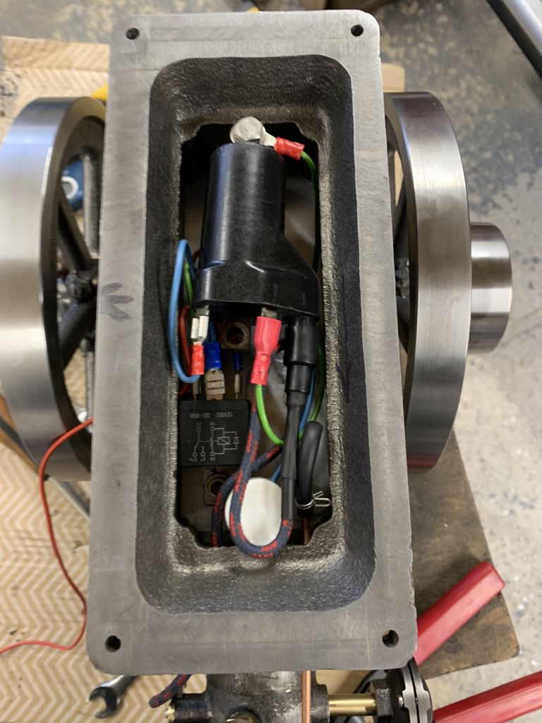
I think this happened because I am using a 12v battery (I don’t have a charger for 6v) looking around the internet I think the trigger signal is 5v and the spark is generated at the end of the pulse. So I bought a 12 to 5v car USB charger and pulled it apart to make a neat little transformer. To get around the Red Wing points configuration I have used a relay that energises when the points close and I’m using the normally open contacts to send the 5v signal to the coil. This looks to work ok as the engine actually runs!
The only thing I have noticed is that the coil pack is getting warm, it may be I’m paranoid about killing another one or it may be normal, have you noticed this on your set up John ?
I have read somewhere that maybe a resistor is needed in the circuit somewhere but I’m not sure why. The other thing I need to avoid is leaving the engine stopped with the points closed. I could avoid this with a one shot timer relay.
I have not yet had a chance to run the Red Wing but I have run the Wyvern with no problems. I only run the coil on 6 volts (a 6V 4 Ahr gel cell ). The Wyvern points are cam operated and are open ( coil energized ) for 160 deg. of crank rotation, which gives a duty cycle of about 22%. With the way the Red Wing points are configured however they are open (coil energized ) most of the time and are only closed for 45 deg. of crank rotation, which gives a duty cycle of about 87.5%. I had previously experimented with the coil on the bench in both configurations and had not noticed any over heating. I just tried it again on the bench, in the configuration with the points open (coil energized ) and after 3 minutes the coil was becoming too hot to touch, that was on 6 volts and the coil was drawing 3.6A. I can see now that the way the Red Wing points are configured keeps the coil energized for too long causing it to overheat. It would be even more so when run on 12 volts. Two possible ways around this would be to one: modify the timing gear, replacing the insulating ring and the copper contact with a brass ring with a short insulating section to give a duty cycle in the neighborhood of 10%. Or two, to do something like Ian did to invert the output of the points.
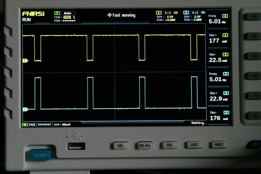
I decided to try the latter and used a single NPN transistor to invert the output of the points. This worked well so I then bread boarded a 555 timer chip to give a 5Hz pulse with a 10% duty cycle to simulate the points with the engine running at 600 RPM (probably fast for a hit and miss engine ). Using these pulses to switch the transistor and the coil resulted in the coil sparking at a freq of 5 Hz and drawing current for only 10% of the time. After running for 30 minutes the coil was just warm to the touch. In the vehicle these coil are mounted directly on the head and according to my son are too hot to touch when the car has been run for awhile so are designed to run hot.
Here's a shot of the scope screen showing the output of the pulse generator (top trace ) and the output of the transistor connected to the IB input of the coil ( bottom trace ).
My engine seems to work fine , it has ran for about 3 hrs the only electrical issue is a sooted up plug! Here’s a picture of the wiring in the engine base. I used 6mm aluminium for the tank base so I could screw things on to it, the 5v transformer is just taped on top of the relay, I also managed to pare the plastic of the coil output and thread it m4 ready for the plug lead.
Good to hear your engine is running well. For general info here are the circuits I have used. The top one is the engine simulator for testing on the bench. A 555 timer configured in astable mode to simulate the points on the running engine switching the transistor/coil to fire the plug.
The lower one is the transistor/coil assembly as installed on the engine. The transistor is not critical, any low power NPN transistor will do. It's only switching 6 volts at less than a milliamp at a very low frequency. I'm not sure the 1K resistor connected to the coil is necessary but was connected to the coil when I tested it so just left it. With the points open the transistor base is high turning it on, holding the coil IB terminal low. When the points close the transistor is turned off setting the IB terminal high energizing the coil. When the points open the plug fires.
I'm not sure how they happened, but I just noticed there are a couple of errors in the above schematics. The "6" on the line between the 4.7K resistor and the base of the transistor shouldn't be there, and the 22k resistor should be 33K. The corrected schematic is here. These values give an square wave output on pin 3 of the 555 timer chip of 5 Hz at a duty cycle of 11%.
Well I’ve managed to kill another coil ! It’s ran maybe 20 hours or so but now the spark has gone! I think I may have left it on for 20 minutes or so with the coil signal energised with 5v, I’m not sure about this but I done think the 5v trigger pulse is too long as it’s on for one sixteenth of a revolution of the timing gear which is maybe 10ms.
So I’ve gone old school with a conventional motorcycle coil and condenser I had laying around, I’m still using the relay as points ….. I wonder how long it will last.