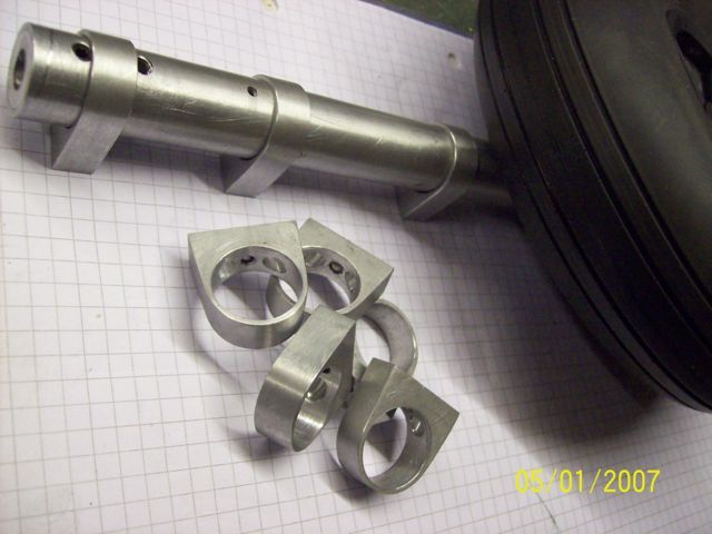
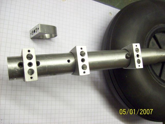
I recently had to make a batch of six aluminium brackets for retracting undercarriage legs on a ¼ scale model of the famous Hurricane fighter aircraft. The brackets were essentially rings, to fit round the legs, with a rectangular boss to which would be attached the undercarriage door. Brackets are locked to the leg via a single grubscrew, and doors are attached to the rectangular boss with M2 bolts. The ring part is ⅜" deep and has a wall thickness of 1/16" . The photos below shows finished brackets in place …. (yes, I know there are more than six, and also that I forgot to reset the camera date, again) …..


I hit on the following method for making the ring part of the brackets, and whilst it has almost certainly been done before it was original thought for me, and as it might not yet have occurred to others I thought I'd share it. So for what it's worth, here it is.
Whenever I'm to radius the end of a part, with a concentric hole, I make a pair of what I call 'filing buttons' from silver steel, and harden them. With two diameters, one to fit halfway into the hole, and the other to give the finished radius, the pair of buttons provide filing guides, and work very well. For these aircraft parts I used an extension of this technique in the milling machine.
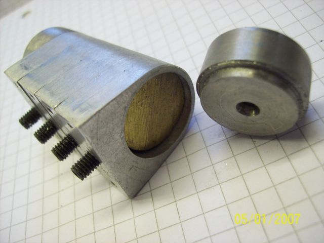
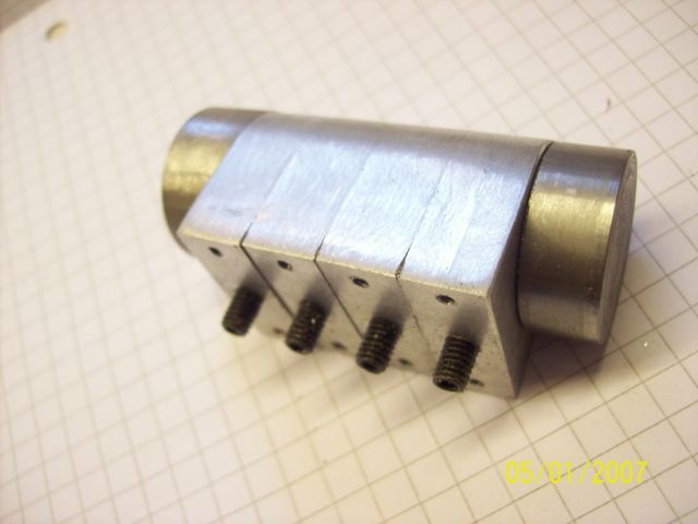
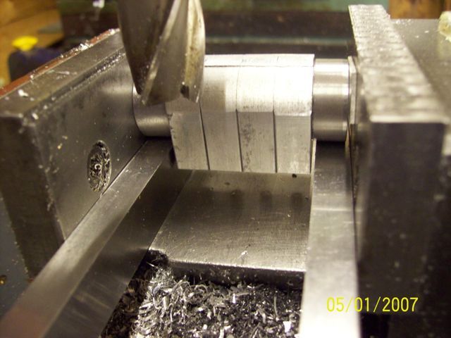
Firstly I made six ¾" dia holes in ⅜" x 1" bar and cut it into six pieces. These were slid onto a short length of ¾" rod, leaving space at the ends for the insertion of two 'buttons'. In the following photos I'm using finished parts to illustrate the method as I lacked the foresight to photograph as I went along, nor had any thought of making it a thread here. In the next two photos you see a stack of four parts being assembled …. (the vice can't take six) ….

and here with a 'button in each end ……..

You can see that each part is already drilled, tapped, and has a grubscrew fitted, which I used to lock them to the inner rod. This is not an essential feature, and plain pieces will stay aligned equally well once machining starts. The assembled package was then placed in the milling machine vice, with each 'button' resting on a parallel, as shown here ……

Cutter height was adjusted until it just cleared the 'buttons', then multiple cuts were taken to produce a series of narrow facets very close to the finished curve. This was simply achieved because the 'buttons' ride on the parallels and all that is needed is to slacken the vice, roll the stack slightly, retighten and take the next cut. After facetting was complete the stack was transferred to the bench, where very little filing was required to blend the facets to the finished curve.
Hope someone finds that useful,
Regards, Ken.
IanT.


