[Project 3] Dickson T1 Tool Holder

Advert

[Project 3] Dickson T1 Tool Holder

Home Forums Work In Progress and completed items [Project 3] Dickson T1 Tool Holder

Viewing 25 posts - 1 through 25 (of 39 total)
  • Author
    Posts
  • #473803
    Lee Jones 6
    Participant
      @leejones6

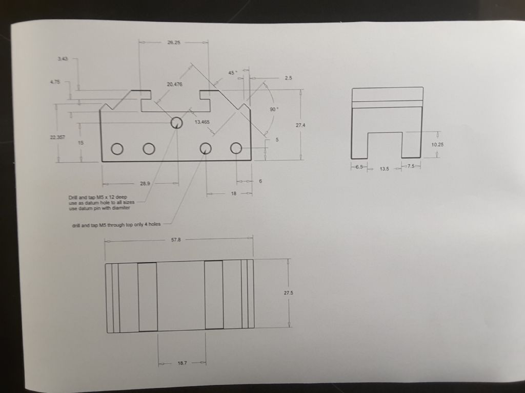
      Probably a little adventurous for someone at my level, but I do so like a challenge.

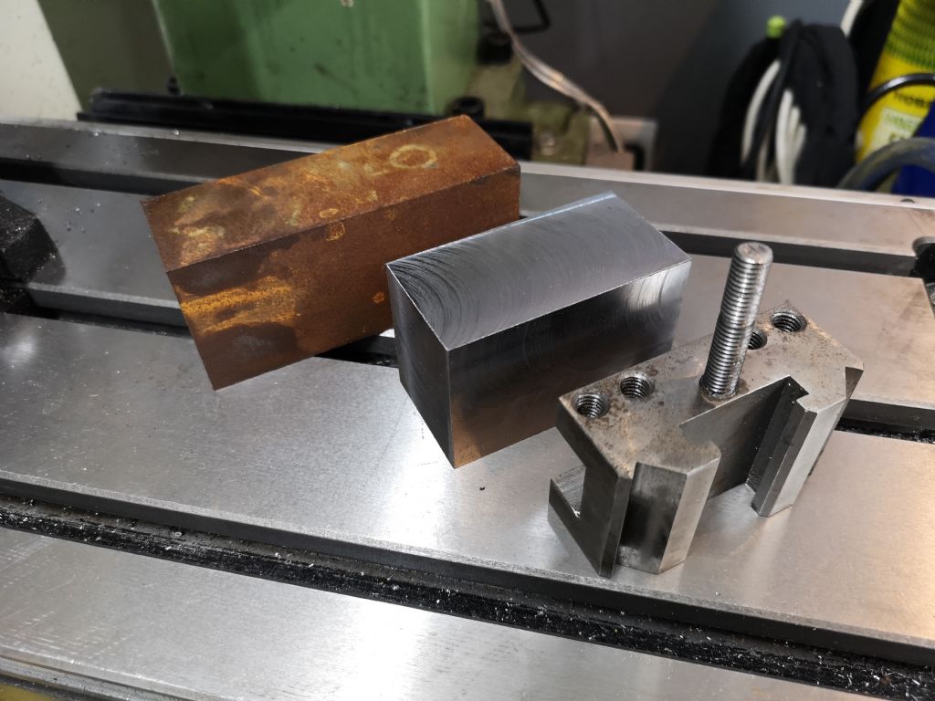
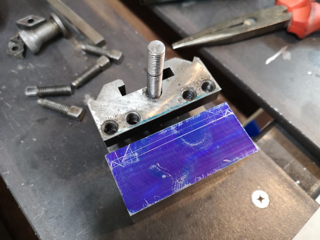
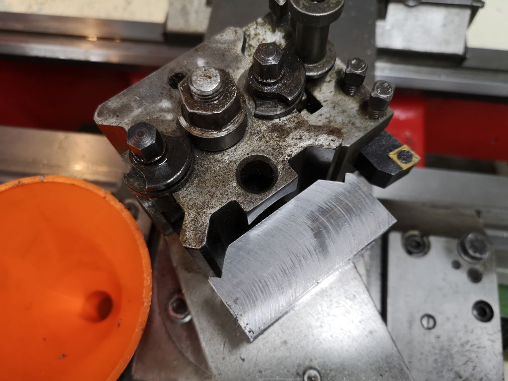
      From back to front;

      • Stock
      • Rough-cut Part
      • OEM Part

      img_20200515_185801.jpg

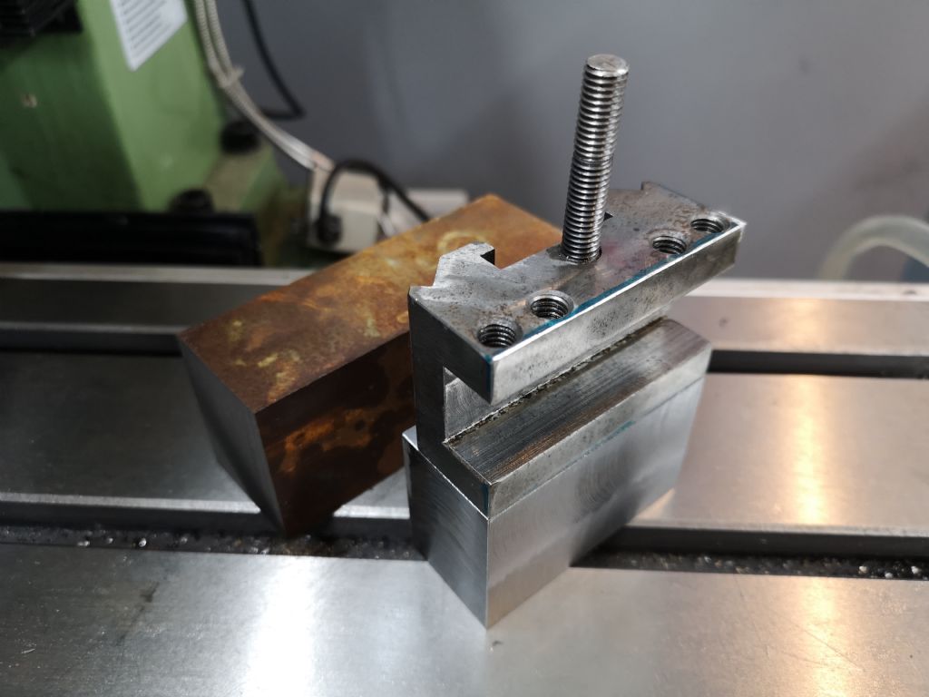
      Part milled to size:

      img_20200516_110834.jpg

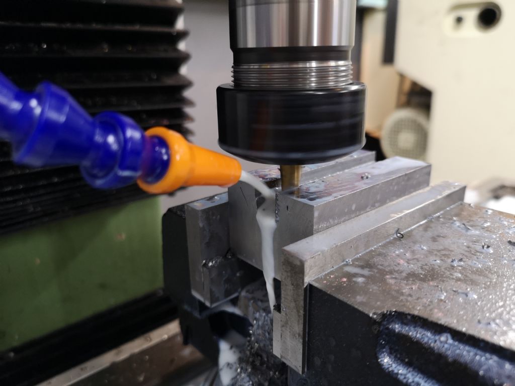
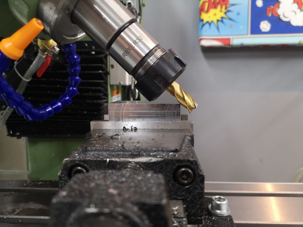
      Tool holding slot being milled with a 10mm 2-flute Carbide titanium nitride (TIN) coated HSS cutter:

      img_20200518_201613.jpg

      Edited By Lee Jones 6 on 22/05/2020 07:53:50

      Advert
      #31297
      Lee Jones 6
      Participant
        @leejones6
        #473805
        Lee Jones 6
        Participant
          @leejones6

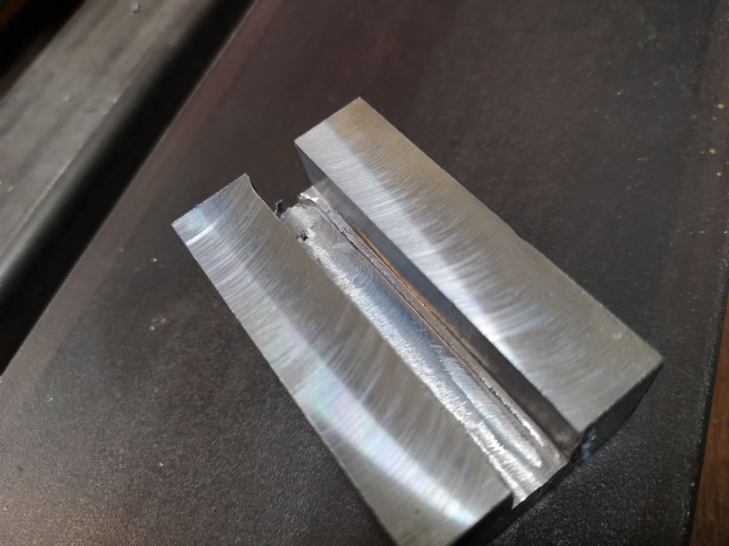
          Bump in the road.

          Looks like the cutter was pulled into the work on the last pass. Typical!

          img_20200518_204034.jpg

          Multiple failings on my part:

          • A 10-11mm collet was used (should have used 9-10mm)
          • The collet was not properly inserted/clicked properly into place (at least not intentionally!)
          • The collet needed de-burring

          Discussion HERE.

          Edited By Lee Jones 6 on 22/05/2020 07:58:42

          #473806
          Lee Jones 6
          Participant
            @leejones6

            Marking out for the 'V' slots.

            img_20200516_112609.jpg

            Discussion for cutting the slots HERE.

            #473808
            Lee Jones 6
            Participant
              @leejones6

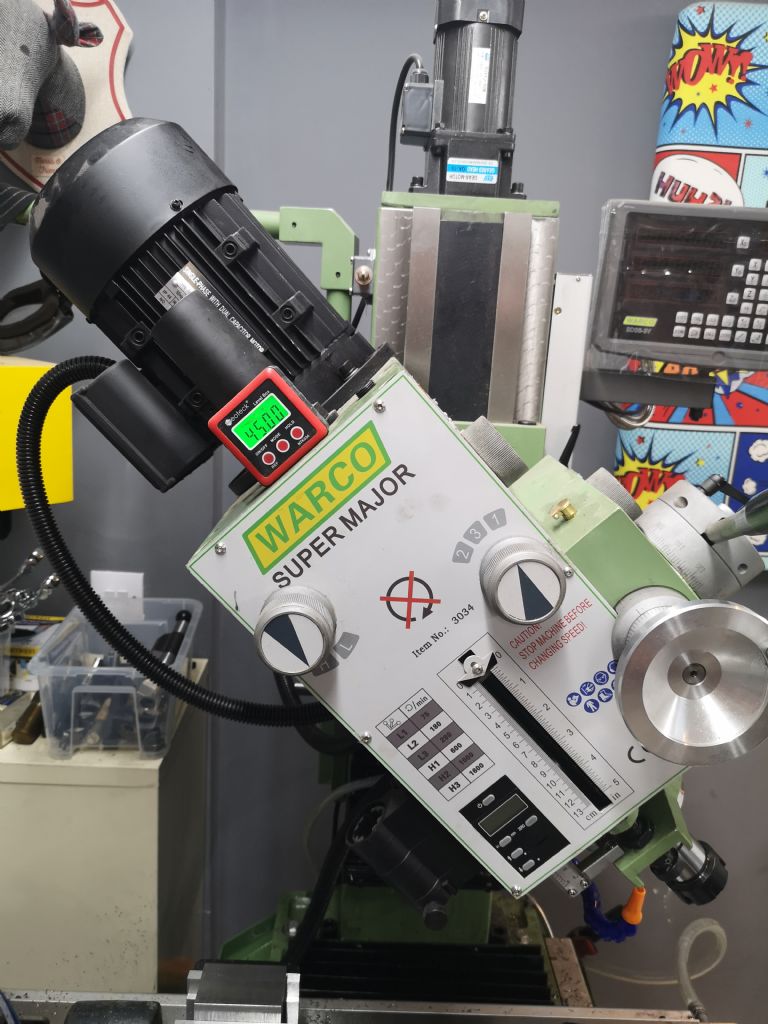
              Tilting the head (first time I did this).

              As you can see, I do not have an accurate way of measuring angles.

              Plan for [Project 86] is a Sine Bar/Plate.

              img_20200520_193458.jpg

              First cut:

              img_20200520_195320.jpg

              One side done (look under the OEM Part):

              img_20200520_205552.jpg

              Both sides done (looks okay to me):

              img_20200521_140943.jpg

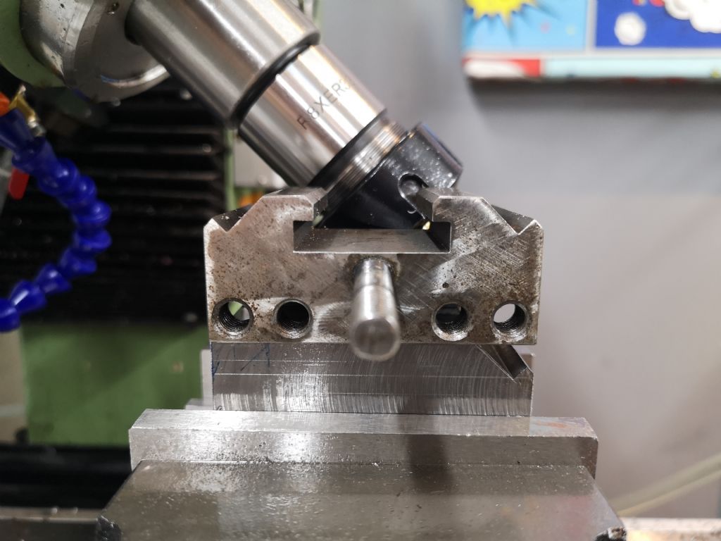
              Offering up to the tool holder. Can't see how it fits until we mill part of the 'T' slot out.

              img_20200521_145633.jpg


              Edited By Lee Jones 6 on 22/05/2020 08:24:15

              #473810
              Lee Jones 6
              Participant
                @leejones6

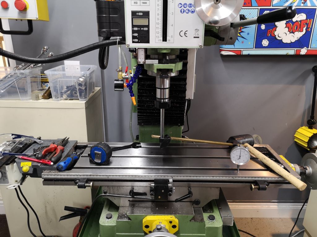
                Tramming the head back in to 0° (vertical):

                img_20200521_192422.jpg

                How does 0.1mm over 480mm sound?

                So 1mm over 4800mm (4.8m)?

                #473865
                thaiguzzi
                Participant
                  @thaiguzzi

                  After making the first one successfully, will you be making them in a gang of 3,4,5?

                  Much quicker, then saw off to length/width.

                  Looks like a good start so far.

                  #473872
                  Lee Jones 6
                  Participant
                    @leejones6

                    Yes, that is the plan. I can squeeze 4 in if I do it this way.

                    However, I'd really like to be able to cut the 45 degree 'v' slots on the X, then I could cut more at a time.

                    Still haven't figured out a way to do that yet.

                    #473888
                    JasonB
                    Moderator
                      @jasonb
                      Posted by Lee Jones 6 on 22/05/2020 08:21:14:

                      How does 0.1mm over 480mm sound?

                      As nobody else has answered from last night I get about 1/10th of that in X&Y eg 0.003mm in 140mm on a Chinese machine.

                      #473889
                      Lee Jones 6
                      Participant
                        @leejones6
                        Posted by JasonB on 22/05/2020 12:43:18:

                        Posted by Lee Jones 6 on 22/05/2020 08:21:14:

                        How does 0.1mm over 480mm sound?

                        As nobody else has answered from last night I get about 1/10th of that in X&Y eg 0.003mm in 140mm on a Chinese machine.

                        I'll go beat it a few more times with a rubber mallet.

                        It was dialed in until I bolted the head down.

                        #473898
                        JasonB
                        Moderator
                          @jasonb

                          You just need to see how much it moves when you tighten it down and then set it to compensate.

                          #473910
                          David George 1
                          Participant
                            @davidgeorge1

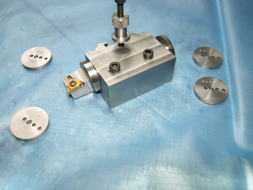
                            This is a drawing of a standard toolpost using a screw with a plain shank to check sizes from to make sure that the clamp mechanism works the same on all replacement pieces.

                            20191208_192606_003.jpg

                            David

                            #473930
                            Lee Jones 6
                            Participant
                              @leejones6

                              Sorry David, I'm not sure I understand.

                              NB: This is the smaller T0 size holder, right?

                              #473939
                              KWIL
                              Participant
                                @kwil

                                Lee,

                                Congratulations on having a go, that's the way to learn. I am not trying to belittle your efforts but manual marking out will not be accurate enough.

                                The 45 degree must be correct, all 4 faces of the Vs need to be in contact, the distance betwen them must be spot on.

                                I have made several for special applications but then my machines have all got DRO facilities. It is unlikely you will be able to file and fit with sufficient accuracy, but you can always try.

                                Good luck

                                #473944
                                KWIL
                                Participant
                                  @kwil

                                  Lee,

                                  p6121799.jpeg

                                  Special application as mentioned. Variable angle screw cutting insert holder.


                                  Edited By KWIL on 22/05/2020 15:08:14

                                  #473945
                                  Lee Jones 6
                                  Participant
                                    @leejones6

                                    What was your method for cutting the 'v's?

                                    #473957
                                    KWIL
                                    Participant
                                      @kwil

                                      Block accurately set up at 45 degrees and left fixed for both Vs. Checked with DRO system (ie slope is 1 in 1). One V cut with mill, then vertical and horizontal off sets for the next V (also read from DRO). Second V cut.

                                      #473982
                                      Lee Jones 6
                                      Participant
                                        @leejones6

                                        Apologies Ken, but what is 'block'?

                                        Don't suppose you took a picture?

                                        #474014
                                        JasonB
                                        Moderator
                                          @jasonb

                                          Block of metal you are making the holder from.

                                          Maybe quill could elaborate on his holding methods.

                                          #474015
                                          Lee Jones 6
                                          Participant
                                            @leejones6

                                            Ah, I thought 'block' was the holding method (like 'v' block). Thanks for clarifying.

                                            Yes, that's what I'm after. How did you mount it at 45 degrees?

                                            #474026
                                            Martin Connelly
                                            Participant
                                              @martinconnelly55370

                                              Lee, did you see this by John Baron on the Cutting a 45 degree V thread page 1? There was also a suggestion somewhere to cut a narrow slot first then cut the vee. This is how some of the purchased ones I have had their vees cut (the slot that is, not the 45 degree cutter part).

                                              Martin C

                                              Hi Lee, Guys,

                                              Whilst your picture shows one way of getting a 45 degree angle, its not a good way of holding work for milling. My recommendation would be to buy a proper inverted cutter and secure the work to the mill table properly. At a pinch you could use a 45 degree HSS or carbide countersink and take it easy with the cut.

                                              Edited By John Baron on 20/05/2020 14:58:32

                                              #474195
                                              KWIL
                                              Participant
                                                @kwil

                                                Lee,

                                                The block was held in a very substantial vice, initial 45 degree set by angle guage, then checked using contact probe at two points in vertical and horizontal plane. As said above, 45 degrees is 1 in 1 slope, so with zeroed probe you should get an equal vertical movement for each horizontal movement. If not you just have to tap adjust until you do, tighten and try again.

                                                Only suitable for one off making not mass production.

                                                #474567
                                                Lee Jones 6
                                                Participant
                                                  @leejones6
                                                  Posted by KWIL on 23/05/2020 12:36:45:

                                                  The block was held in a very substantial vice, initial 45 degree set by angle guage, then checked using contact probe at two points in vertical and horizontal plane. As said above, 45 degrees is 1 in 1 slope, so with zeroed probe you should get an equal vertical movement for each horizontal movement. If not you just have to tap adjust until you do, tighten and try again.

                                                  Only suitable for one off making not mass production.

                                                  Ah yes, I see. Thanks for getting back to me. I'll add the 1:1 technique to my toolbox.

                                                  #474568
                                                  Lee Jones 6
                                                  Participant
                                                    @leejones6
                                                    Posted by Martin Connelly on 22/05/2020 18:58:38:

                                                    Lee, did you see this by John Baron on the Cutting a 45 degree V thread page 1? There was also a suggestion somewhere to cut a narrow slot first then cut the vee. This is how some of the purchased ones I have had their vees cut (the slot that is, not the 45 degree cutter part).

                                                    Martin C

                                                    Hi Lee, Guys,

                                                    Whilst your picture shows one way of getting a 45 degree angle, its not a good way of holding work for milling. My recommendation would be to buy a proper inverted cutter and secure the work to the mill table properly. At a pinch you could use a 45 degree HSS or carbide countersink and take it easy with the cut.

                                                    I did see both of those posts, thank you.

                                                    Not overly keen on using a countersink for this.

                                                    Seen some 45 degree side cutters and was considering something like THIS.

                                                    I think I'm going to go for a sine plate, 'cos why not (and I think I'll get use out of it beyond this project).

                                                    #474576
                                                    Lee Jones 6
                                                    Participant
                                                      @leejones6
                                                    Viewing 25 posts - 1 through 25 (of 39 total)
                                                    • Please log in to reply to this topic. Registering is free and easy using the links on the menu at the top of this page.

                                                    Advert

                                                    Latest Replies

                                                    Viewing 25 topics - 1 through 25 (of 25 total)
                                                    Viewing 25 topics - 1 through 25 (of 25 total)

                                                    View full reply list.

                                                    Advert

                                                    Newsletter Sign-up