Problems with NVR switch

Advert

Problems with NVR switch

Home Forums Electronics in the Workshop Problems with NVR switch

Viewing 21 posts - 1 through 21 (of 21 total)
  • Author
    Posts
  • #396285
    Miles Hellon
    Participant
      @mileshellon

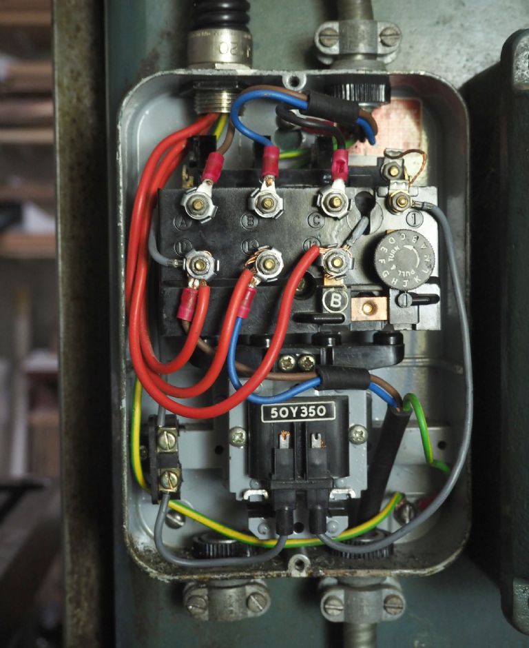
      Just wired up a Tom Senior mill. 400V 3 phase from a Transwave static converter to a 0.37 kW motor via a 1960's Brook NVR switch. The switch worked a few times and then nothing….. Activating the solenoid manually (lifting it with a dowel) powers up the motor. I've taken it all apart and there don't appear to be any loose connections….

      Any suggestions?

      Thanks.

      Miles

      Advert
      #32002
      Miles Hellon
      Participant
        @mileshellon

        Solenoid not activated by On button

        #396286
        Miles Hellon
        Participant
          @mileshellon

          p2140789.jpg

          #396287
          Brian Wood
          Participant
            @brianwood45127

            Miles,

            The black two core [red and blue] and earth cable which exits bottom right, what does that go to please?

            Regards

            Brian

            #396291
            Miles Hellon
            Participant
              @mileshellon

              Hi Brian,

              That's the output to the machine light. You can see the edge of the light switch casing to the right of the NVR switch.

              Regards,

              Miles

              #396292
              Les Jones 1
              Participant
                @lesjones1

                I suspect that a thermal overload has tripped and needs resetting.The round knob on the right looks like it could be to set the thermal overload trip current. I expect there to be something in that area that needs resetting. I would also suggest measuring the resistance of the solenoid coil in case it has gone open circuit. (I am thinking it could be a 240 volt coil which is intended to be powered between a phase and neutral but has been connected to be powered between phases.) You could also check that all safety interlock switches are closed and that the stop buton is not open circuit. (The stop button will be normally closed contact that opens when pressed.)

                Les.

                Edited By Les Jones 1 on 14/02/2019 18:28:10

                #396311
                Miles Hellon
                Participant
                  @mileshellon

                  Thanks Les,

                  I tried increasing the trip current setting (round knob). That did nothing so I returned it to the nearest setting above the rating of the motor current (1.26 A). Can't see anything to reset there.. The resistance across the solenoid coil is 2.45 kOhms. It appears to be connected across L1, L3. Can't see any safety interlock switches. Not sure how to test the stop button….

                  Regards,

                  Miles

                  #396314
                  Emgee
                  Participant
                    @emgee

                    Miles, as Les says the stop button is NC (normally closed) so you should get a reading across the terminals.
                    Same goes for the overload connections, need to closed or the coil won't energise.

                    You say it ran a few times, if this is the case then my earlier thoughts of there not being 400v across the L1 and L3, some static converters only have 400v across 2 cables on the incomer, the 3rd is a ghost so if the control cct is connected to that the coil will not energise.

                    Emgee

                    #396316
                    Miles Hellon
                    Participant
                      @mileshellon

                      Thanks Emgee,

                      The Transwave instructions do say "ensure to swap L1 and L3 output from the converter to reverse motor direction" I need to check that L1, L2, L3 outputs correspond to L1, L2, L3 inputs on the NVR…. I'm used to all three being interchangeable…..

                      Regards,

                      Miles

                      #396324
                      Emgee
                      Participant
                        @emgee

                        Miles, if the light is transformer fed at 400v primary and it is working correctly that would seem to prove 400v on L1 and L2.
                        The coil cct is taken from L1 and L3 at present, the 2 grey conductors, so if L3 is a ghost then you can either move the grey from L3 and connect on L2, you will then be able to leave the light as is.

                        Possibly better to get lines as suggested ref power on L1 and L3, but you will then have to move the light supply line over to L3 from L2, leaving the grey cables in situ.

                        Emgee

                        Edited By Emgee on 14/02/2019 21:03:01

                        #396325
                        Miles Hellon
                        Participant
                          @mileshellon

                          Thanks Emgee, that was indeed the key…… In fact there were/are two faults! The first was that when I swapped the converter outputs to change motor rotation direction I connected either L1 or L3 to the L2 input terminal in the NVR switch. The second fault is that the start button only works if it's pressed in a certain way! You need to press on the right side of the button. If you press on the left or middle of the button, nothing happens! It was this combination of needing specific phase connections and behaviour of the start button that was so confusing!

                          Thanks to you all for your help with this.

                          Regards,

                          Miles

                          #396328
                          Miles Hellon
                          Participant
                            @mileshellon

                            Emgee,

                            Haven't tried the light yet. No bulb for it. But I know what to do if it doesn't work

                            Thanks,

                            Miles

                            #396334
                            Les Jones 1
                            Participant
                              @lesjones1

                              Is there a transformer between where the black cable comes out of the bottom right hand gland of the NVR and the lamp ? I think it is very unlikely that the bulb runs directly of 400 volts. (I am making the assumption that the static converter contains a 240 volt to 400 volt transformer and the motor is wired in star configuration for 400 volts phase to phase and not in delta configuration for 240 volts phase to phase.)

                              Les.

                              #396340
                              Emgee
                              Participant
                                @emgee

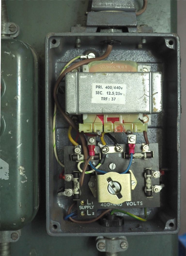
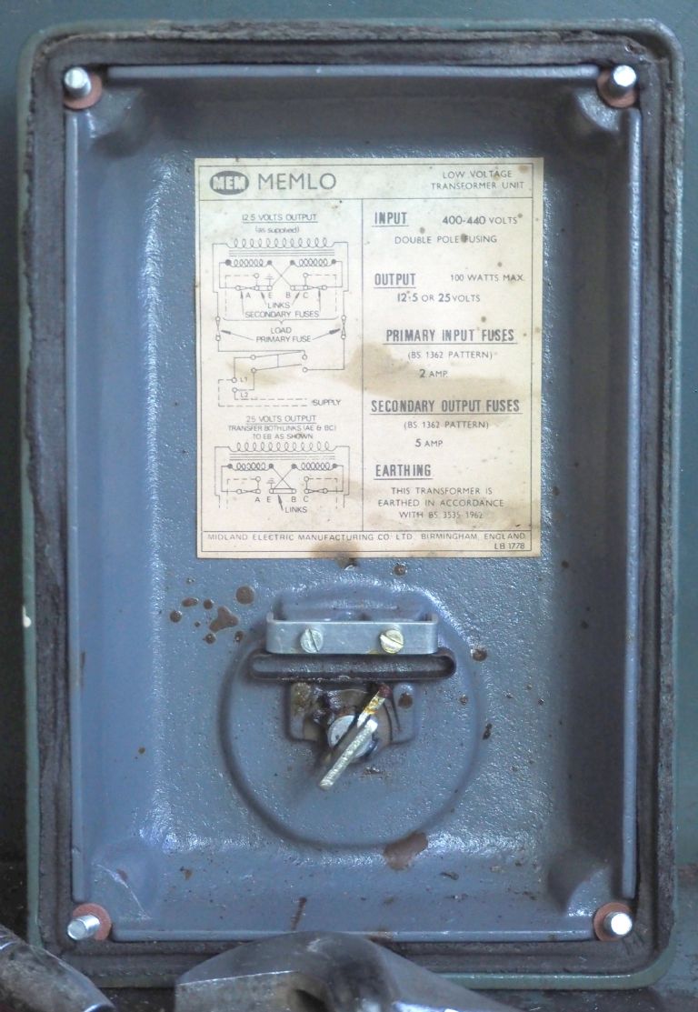
                                Les, most likely a 400v primary with 24/50v secondary, std fitting on most machines of the that Brook starter era.

                                Emgee

                                #396358
                                Miles Hellon
                                Participant
                                  @mileshellon

                                  Les, Emgee,

                                  The light runs on 24V. There is a 12.5V/25V transformer in the light switch box. With the present wiring, the light does work, but only when the machine is running!

                                  Regards,

                                  Miles

                                  p2150790.jpgp2150791.jpg

                                  Edited By Miles Hellon on 15/02/2019 08:23:23

                                  Edited By Miles Hellon on 15/02/2019 08:23:45

                                  Edited By Miles Hellon on 15/02/2019 08:27:56

                                  #396362
                                  David Jupp
                                  Participant
                                    @davidjupp51506

                                    With a different make of contactor, I've had problems with start switch that previously worked no longer doing so. After much messing around I had to move contactor slightly towards the enclosure lid (and the start button), by placing washers between it and the backplate.   Sounds like having to press the start button in a certain way could be the beginning of a similar issue.

                                    Edited By David Jupp on 15/02/2019 08:32:21

                                    Edited By David Jupp on 15/02/2019 08:32:43

                                    #396367
                                    Miles Hellon
                                    Participant
                                      @mileshellon

                                      Hi David,

                                      Thanks. Good idea, I'll try that.

                                      Kind regards,

                                      Miles

                                      #396372
                                      Les Jones 1
                                      Participant
                                        @lesjones1

                                        Hi Miles,

                                        If the light only works when the machine is running I think you have it wired to the output side of the contactor . (The side connected to the motor.) The incoming three phase from the static converter should be connected to the three lower connections (L1, L2, L3) and the motor connected to the three top connections. (A, B, C) If you have it connected with the incoming three phase to the top three terminals I don't see how it could have worked as there would be no power (From L1 & L3.) to power the solenoid. Can you post a diagram of how you have connected it showing which terminals are connected to the three phase from the static converter, which terminals are connected to the motor and how you have connected the start and stop buttons ? (I can't see any wires that look like they go to the start and stop buttons.

                                        Hi Emgee,
                                        I agree that is the most likely way the light would be powered. (That is the way it was done on machines in the factory I worked in in the mid 1960s.) I was thinking it may have been wired with a 240 volt lamp directly to the mains at some point in it's history.

                                        Les.

                                        #396375
                                        Miles Hellon
                                        Participant
                                          @mileshellon

                                          Les,
                                          The light is connected to L1 and L2 input terminals. Because L2 is the ghost phase from the converter, I guess it only becomes active when the motor is running. I’ll changeover the light connection from L2 to L3.
                                          Regards,
                                          Miles

                                          #396388
                                          Les Jones 1
                                          Participant
                                            @lesjones1

                                            The lamp should be connected to L1 and L3 which are the two phases that feed the solenoid. I think you should put some markers on both ends of each of the red wires so you know which are the real phases and which is the ghost phase.

                                            Les.

                                            #396391
                                            Miles Hellon
                                            Participant
                                              @mileshellon

                                              Thanks Les. Yes, I really should mark the phase wires!

                                              Regards,
                                              Miles

                                            Viewing 21 posts - 1 through 21 (of 21 total)
                                            • Please log in to reply to this topic. Registering is free and easy using the links on the menu at the top of this page.

                                            Advert

                                            Latest Replies

                                            Viewing 25 topics - 1 through 25 (of 25 total)
                                            Viewing 25 topics - 1 through 25 (of 25 total)

                                            View full reply list.

                                            Advert

                                            Newsletter Sign-up