Preston’s Oscillator.

Advert

Preston’s Oscillator.

Home Forums Stationary engines Preston’s Oscillator.

Viewing 14 posts - 1 through 14 (of 14 total)
  • Author
    Posts
  • #3382
    JasonB
    Moderator
      @jasonb
      Advert
      #447649
      JasonB
      Moderator
        @jasonb

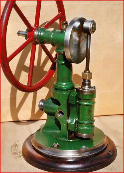
        I have a file on my computer named "future projects" where I store photos of any engines that I think would be nice to make and looking at the date I have liked this subject for the last eight years. It is actually still up for sale at Preston Services where I first saw it but mine worked out a bit cheaper.

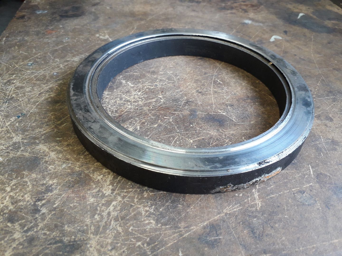
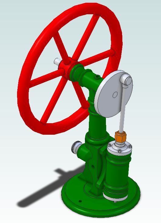
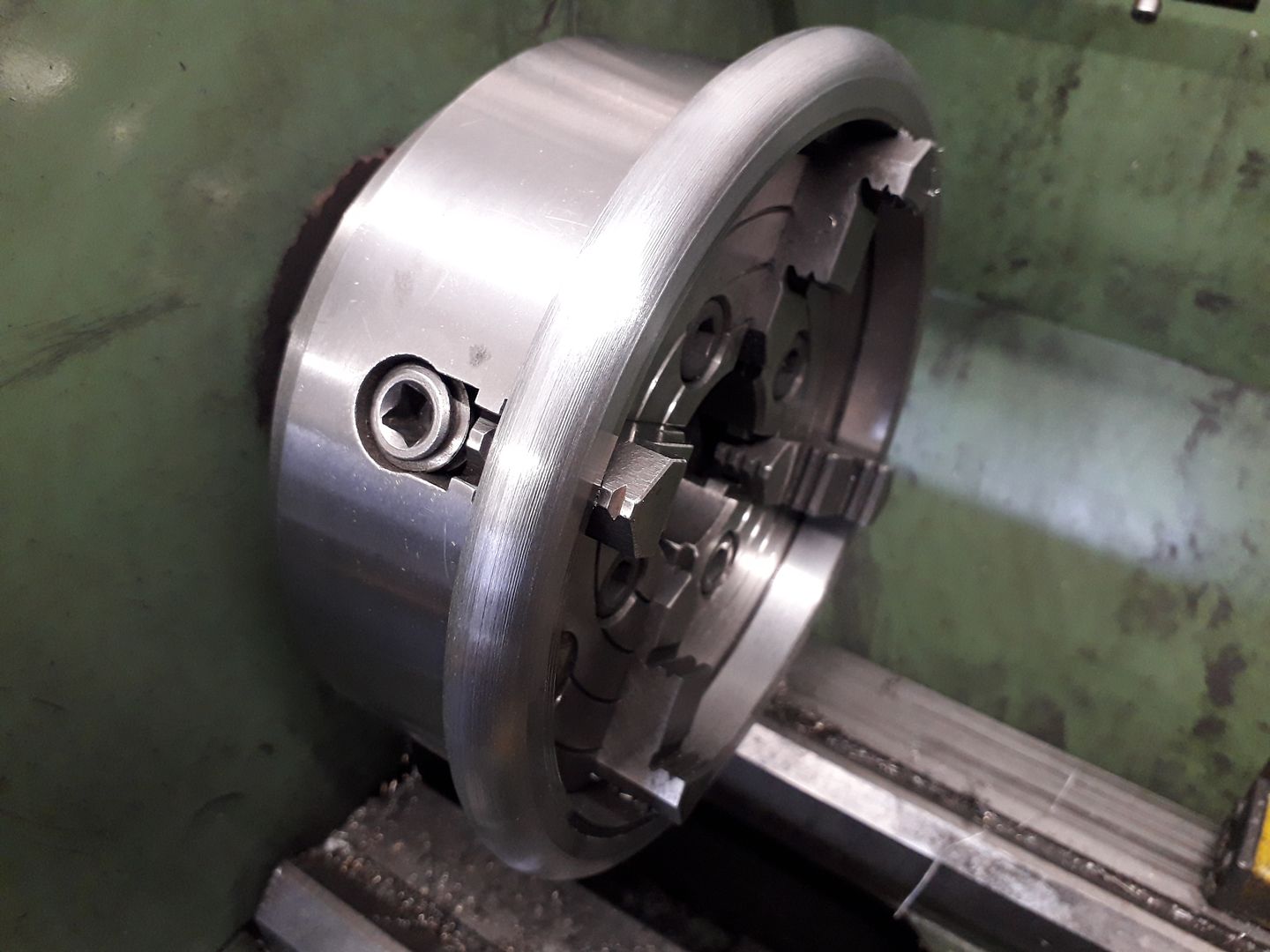
        Unlike a lot of my other engines I decided to make the flywheel this time as it's round section rim is not available as a casting at least not with suitable shaped spokes otherwise the Vulcan beam would have been a suitable donor. A couple of years ago I was given two off cuts of 7" diameter thick wall steel tube so the engine was designed around this fixed size over a couple of evenings using Alibre.

        First job was to clean up the piece of tube to see what thickness rim I could get and that turned out to be 14mm so a 14mm diameter cross section and skim off the black scale to give an OD of 175mm, not the nicest steel to machine but it seemed to clean up OK.

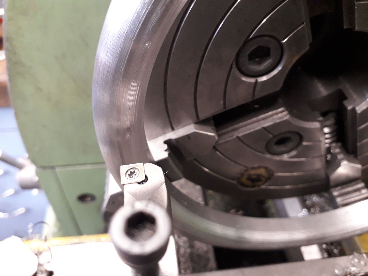
        Next some co-ordinates were worked out at a 0.010" spacing and the outer half of the rim roughed out to those.

        Then gripping the outside edge the inner half was roughed out to the same co-ordinates with a boring bar.

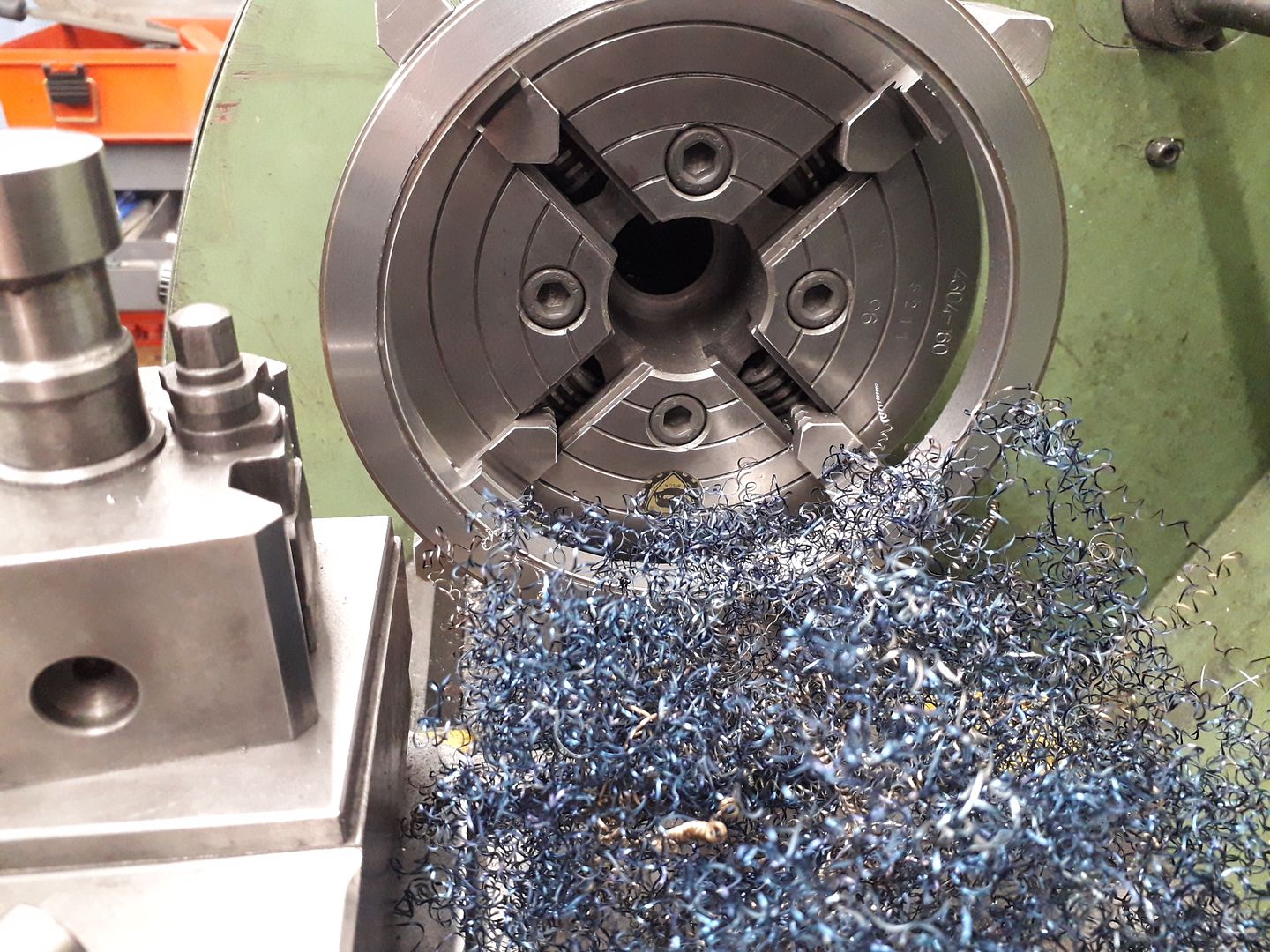
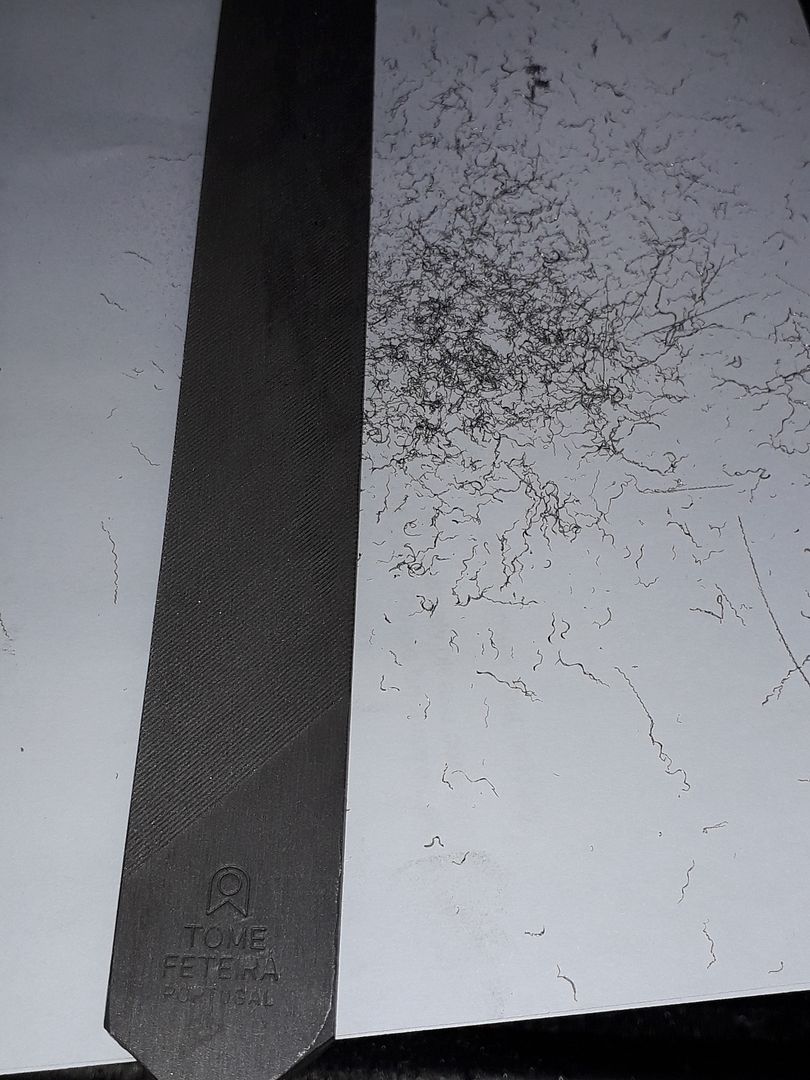
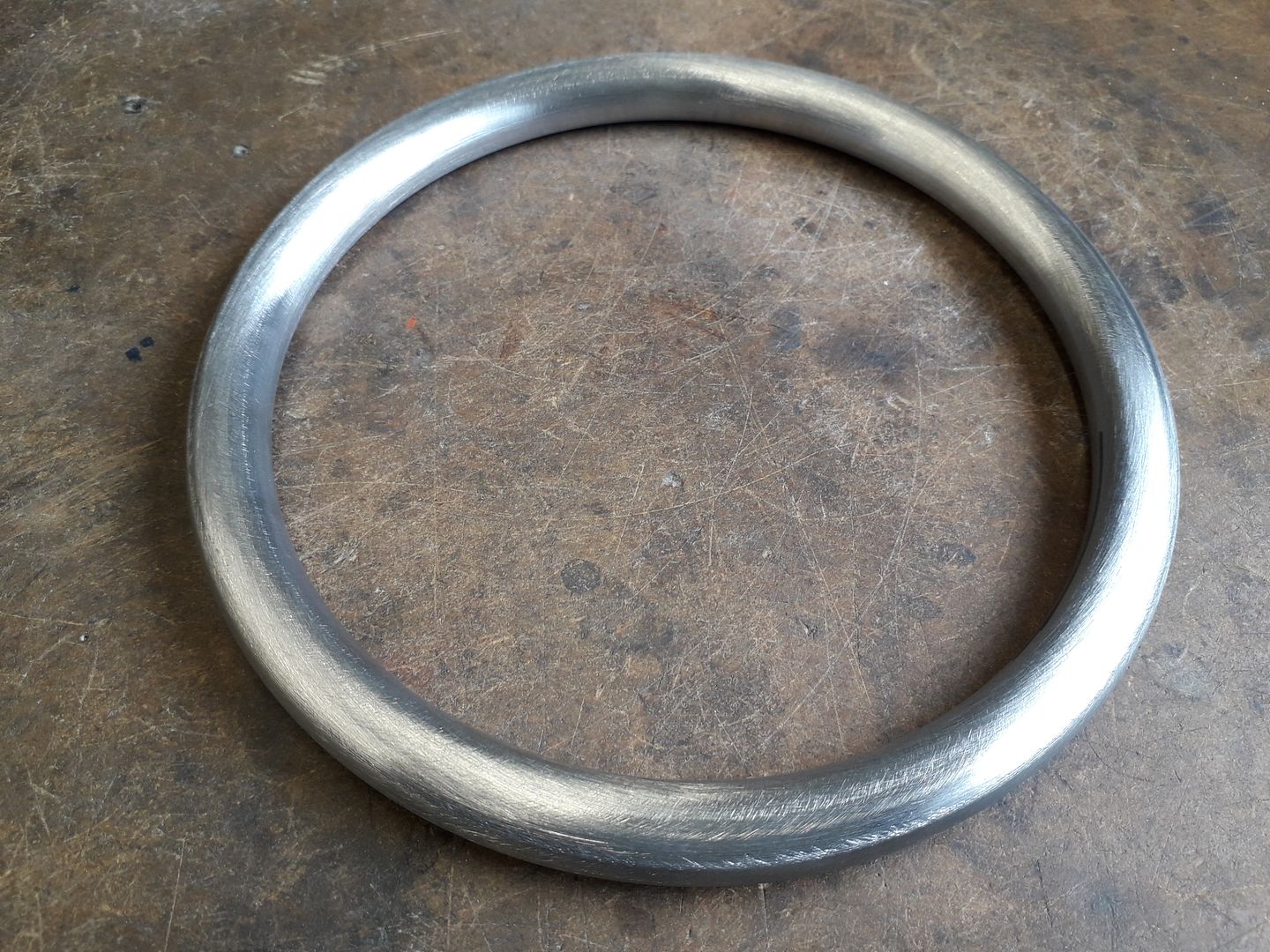
        The stepped finish from the rough cuts was then blended with a long angle lathe file from ARC which worked very well producing fine wisps of swarf then a quick going over with some Rolok abrasive discs in the cordless drill used against the rotating flywheel.

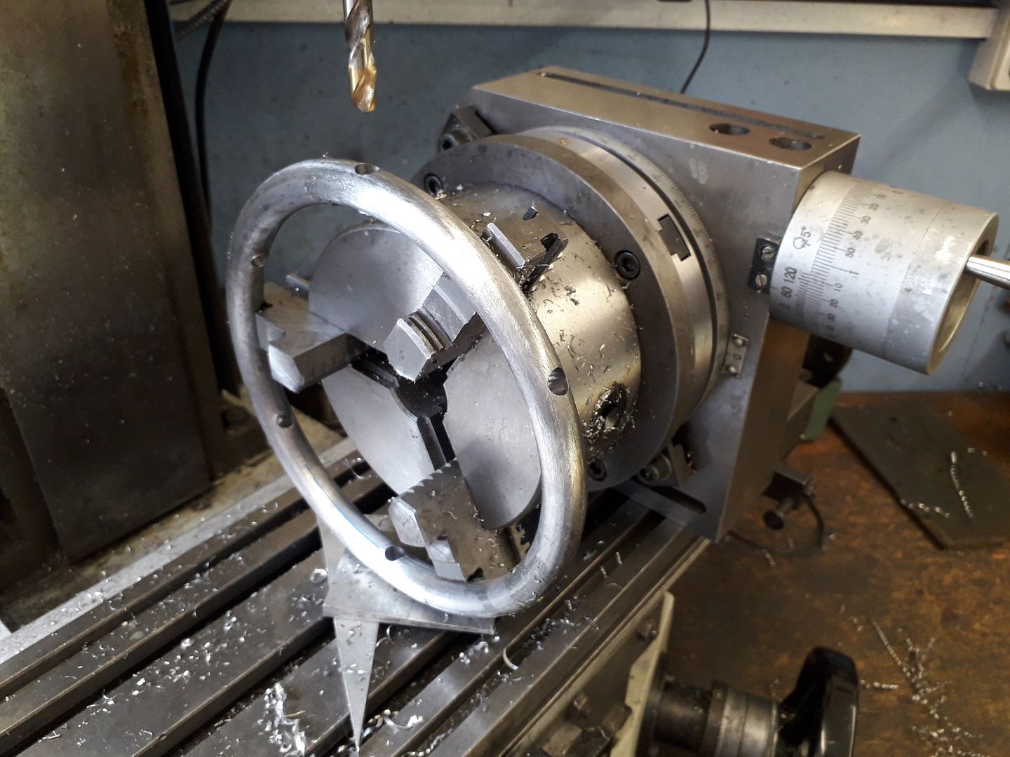
        Then over to the mill to drill through so that the 8mm spokes could be inserted.

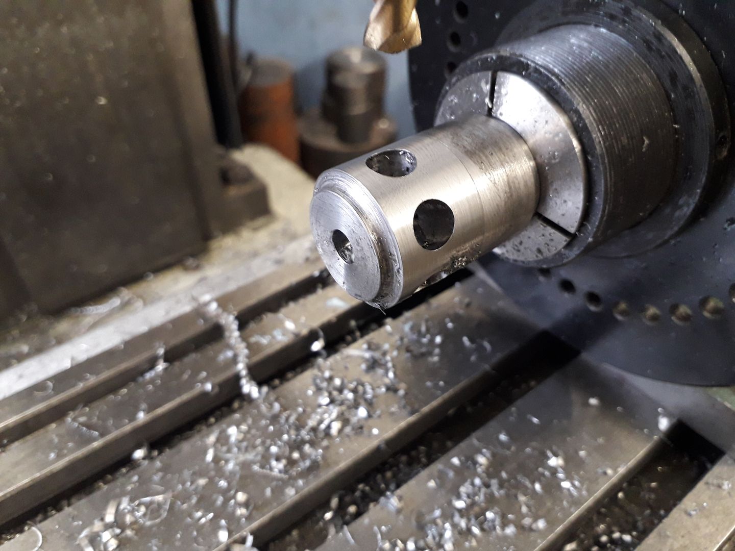
        And a similar operation on the part machined hub that was sawn off and finish turned after drilling, bore is undersize at this stage.

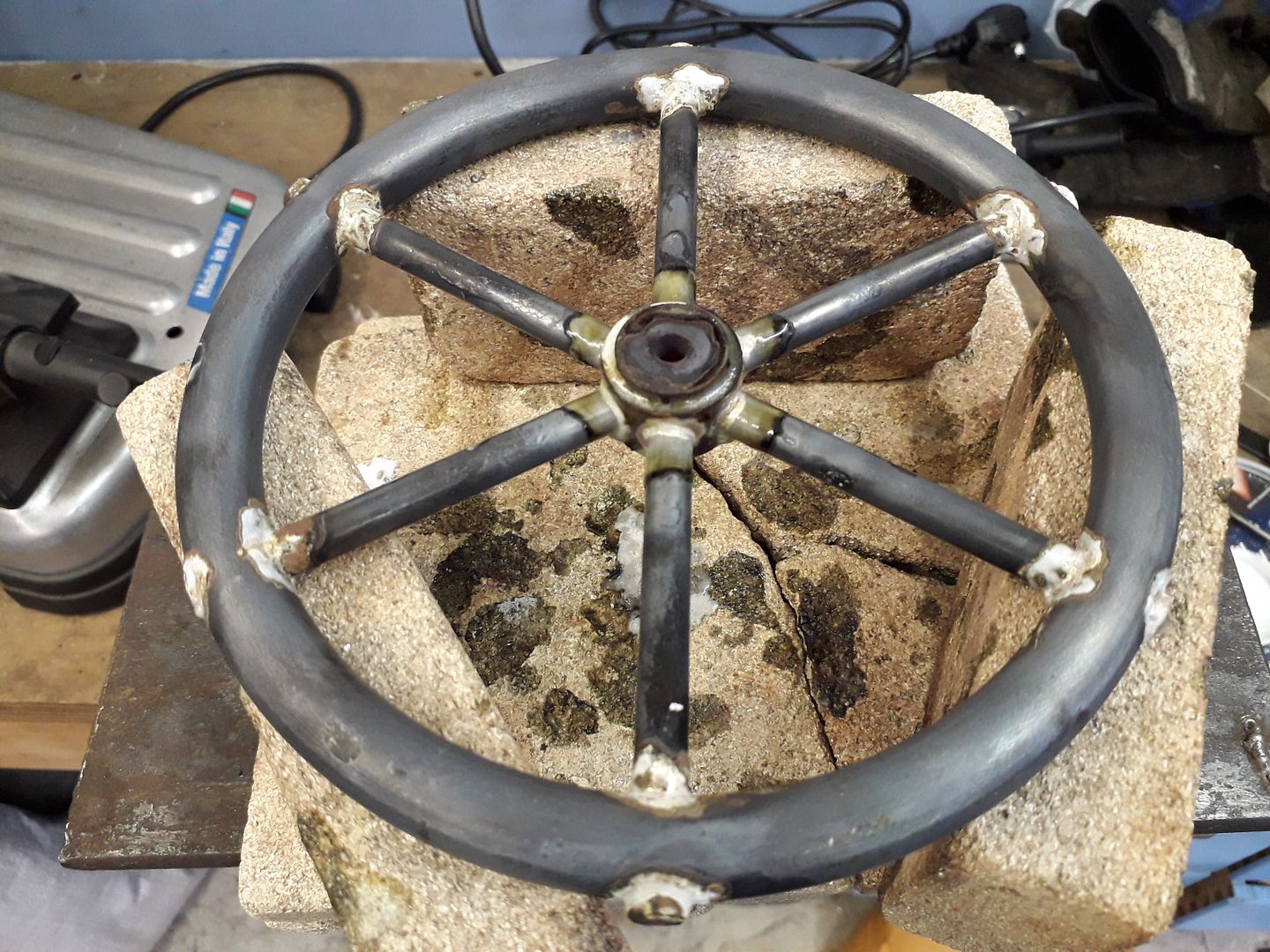
        After a test fit it was all cleaned with thinners and then silver soldered together. I did it in two heats, the first working around the rim one spoke at a time and then when cooled I did the hub. The reasoning being that as the rim would expand the spokes would be free to move in th ehub as it cooled back down rather than risk excess distortion if it were to cool and things ended up in compression or tension.

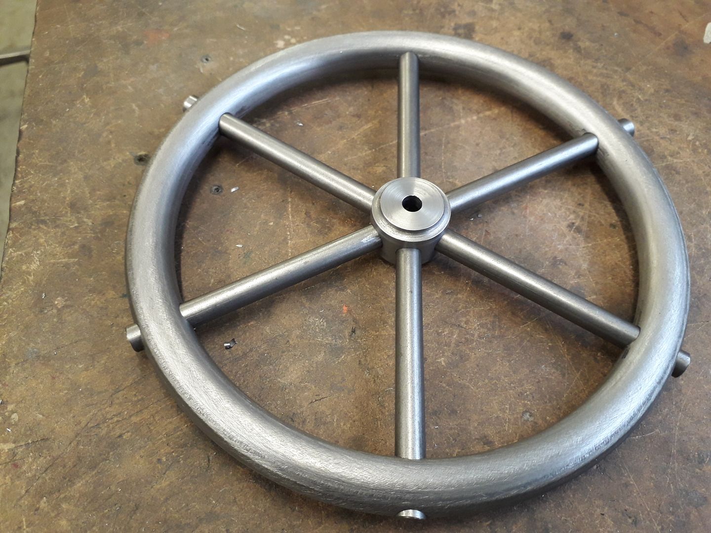
        After a clean up it was put back in the lathe and the rim set to run true so that the hub could be bored out to a nice push fit on the 8mm PGMS crankshaft material.

        #448101
        JasonB
        Moderator
          @jasonb

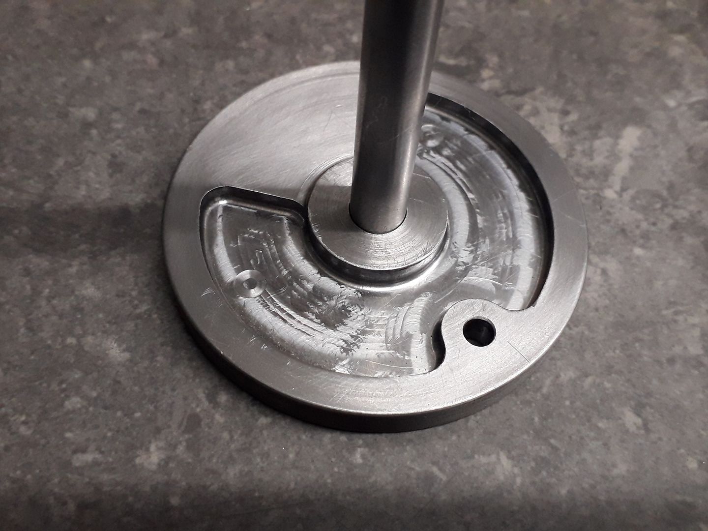
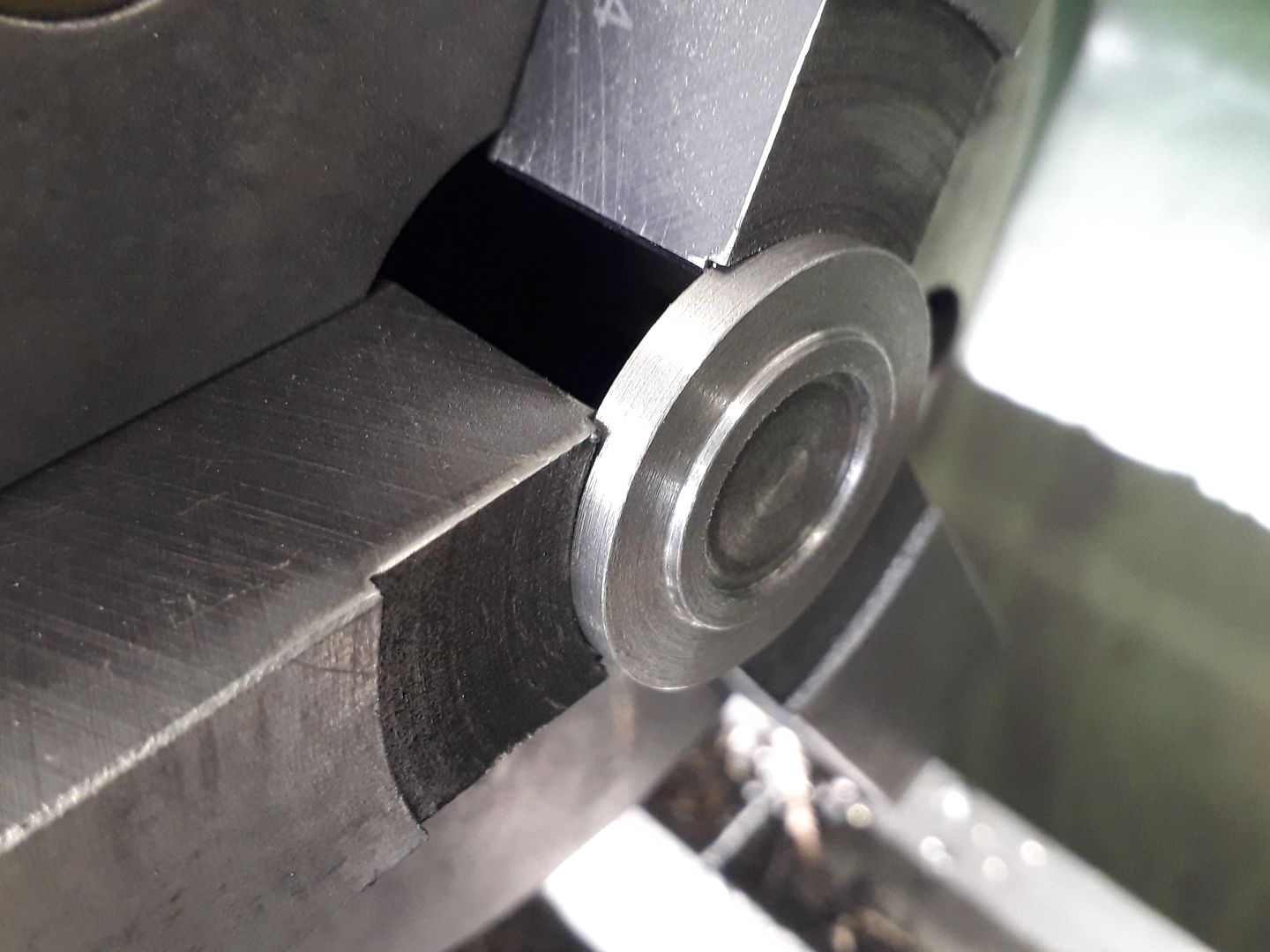
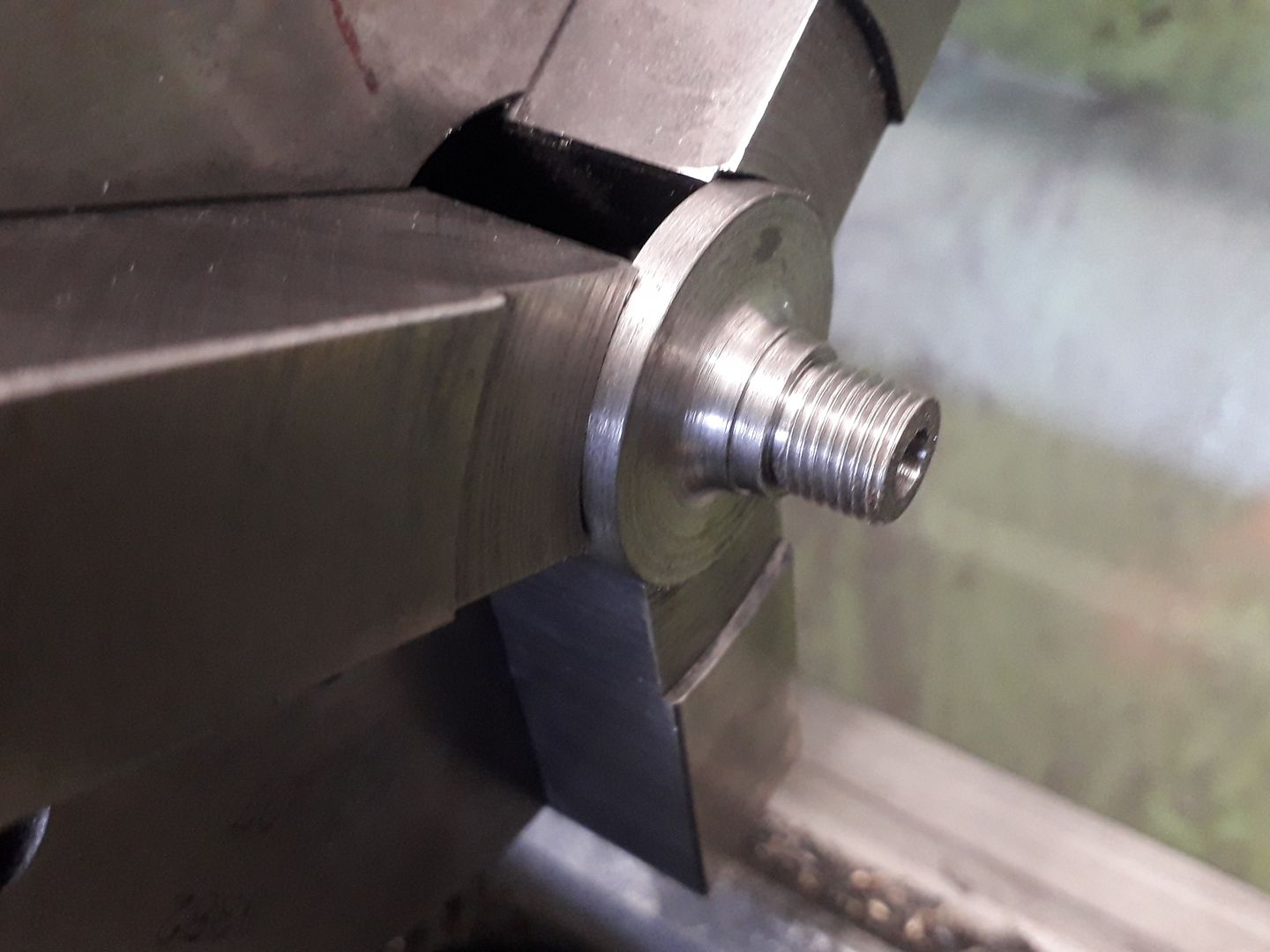
          With the flywheel complete I thought something to go on the other end of the crankshaft would be a good idea so cut off a slice of cast iron and turned to shape in the soft jaws leaving a small fillet in the internal corner of the central boss. I bored the hole to a light press fit on the 8mm shaft and left the disc 0.5mm over thickness.

          Although the photos don't show any form of counterbalance I decided to add some to help get a smooth runner and also add a bit of visual interest to what would otherwise but a bit of a boring large plain disc. The CNC made quick work of it and by using a radius corner milling cutter also go a fillet in the corners to help make it look like the recess was cast into the disc. A drop of Loctite 648 was added and the shaft pressed home, after allowing to set the disc was skimmed down to final thickness while holding the shaft in a collet.

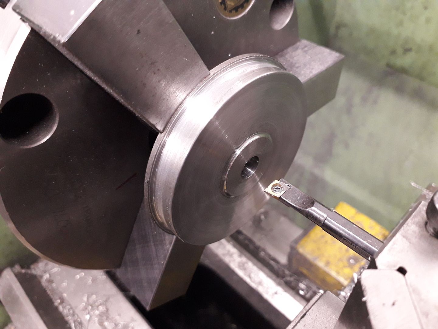
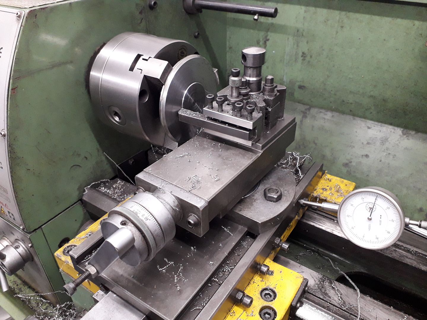
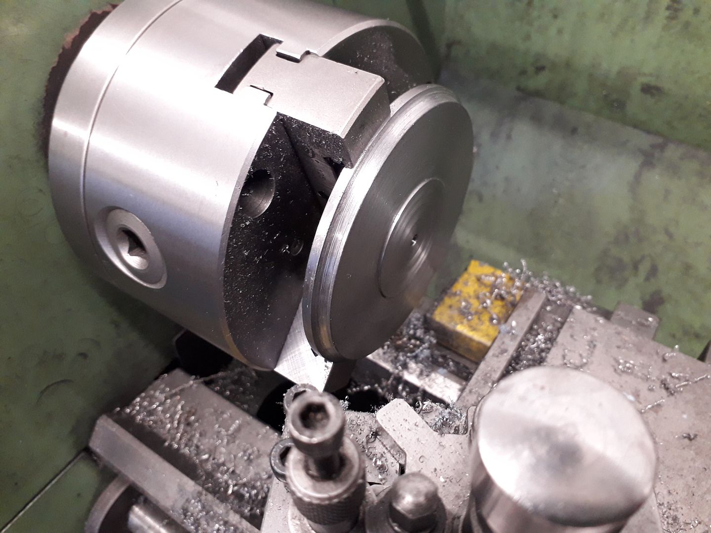
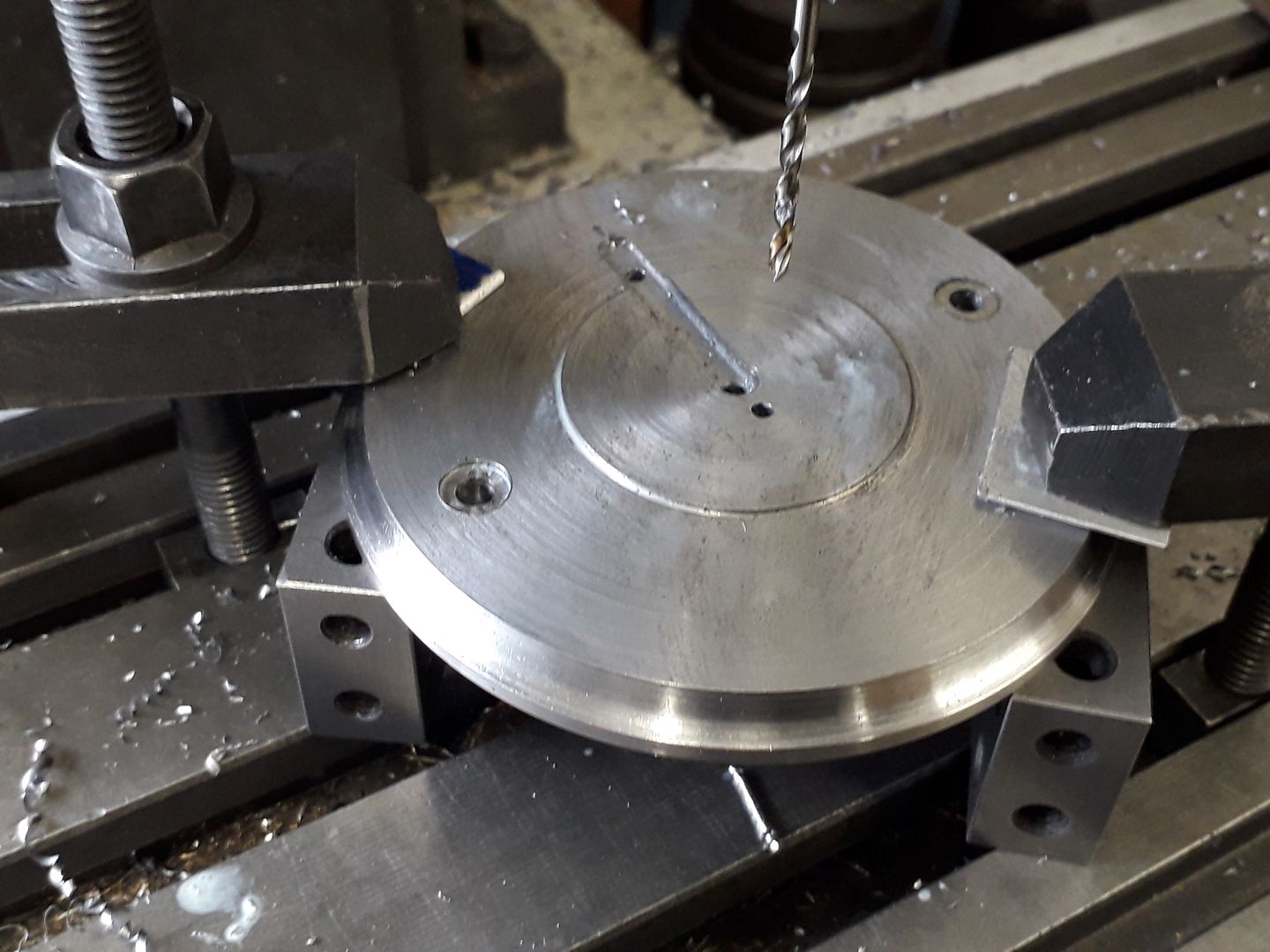
          I then turned my attetion to the main "casting" Starting with a disc of 10mm thick steel that I had water jet cut some time ago while having some other work done, not the nicest of steel to machine but it saved having to saw off a piece of 100mm dia bar. The face was skimmed to remove the mill scale then the topslide swung round to slightly taper the surface upto a flat 40mm central area.

          Then a round nose tool added the decorative cove to the edge.

          Over to the mill to add a couple of hole sto hold things together and a slot to locate the web behind the valve block.

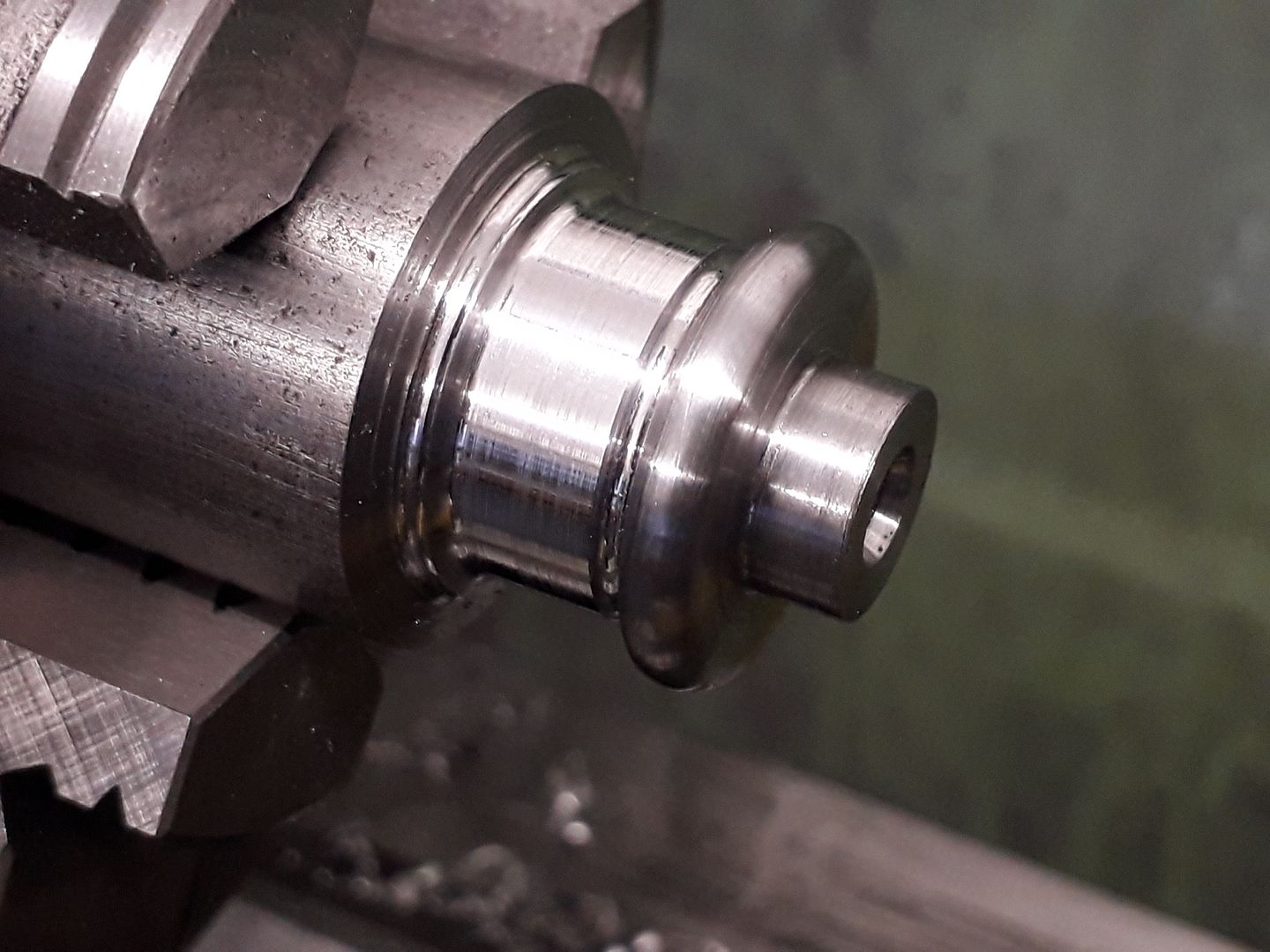
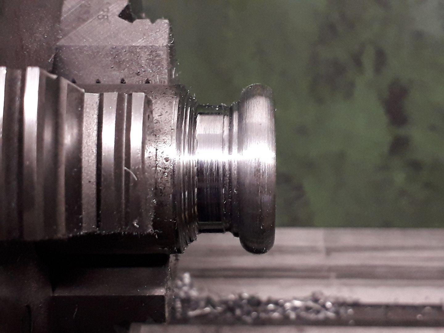
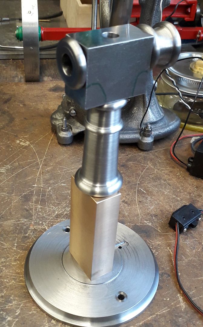
          The top end of the column was turned first with an over length spigot to locate into the top "Tee" piece

          After sawing off the bottom was tapped M6 and ctr drilled before shaping the outside.

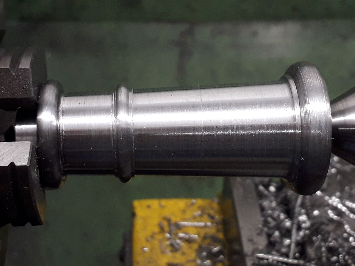
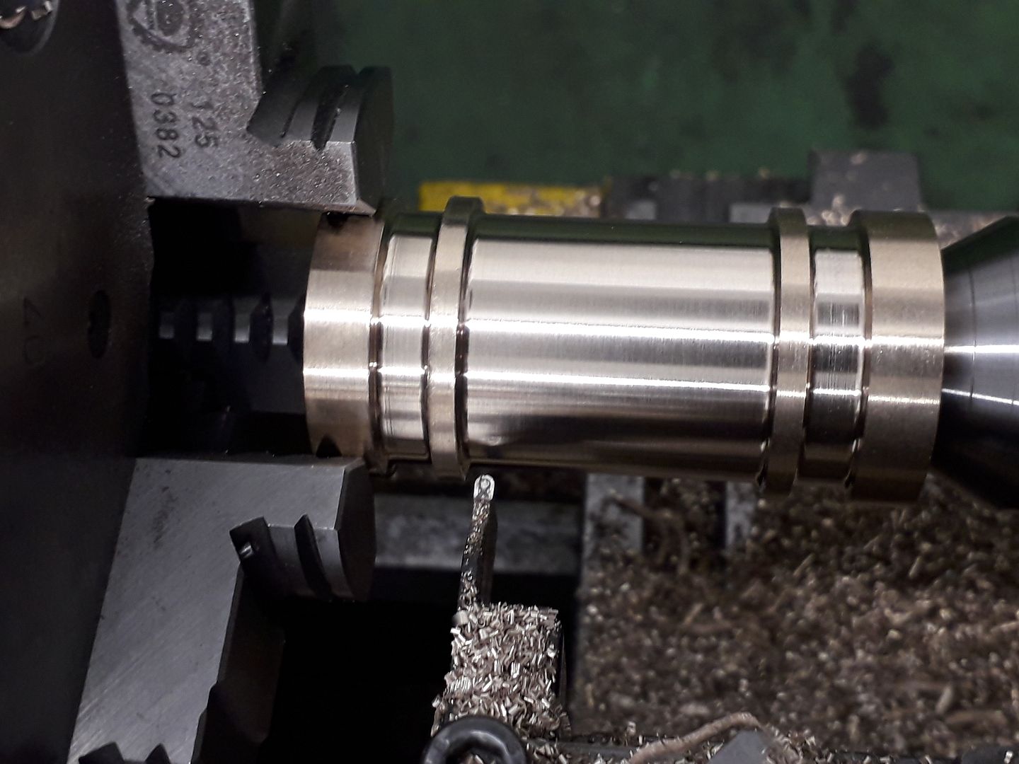
          I could then hold the column by the spigot and use tailstock support to turn the central tapered part.

          I also turned two decorative beaded parts to go onto the horizontal ends of the "Tee" but did not take any photos. The tee itself was a piece of 20×40 steel flat bar machined down to 38mm by 30mm long which was drilled and counterbored for spigots left on the three parts that join onto it.

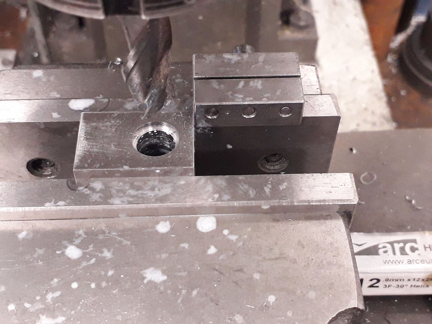
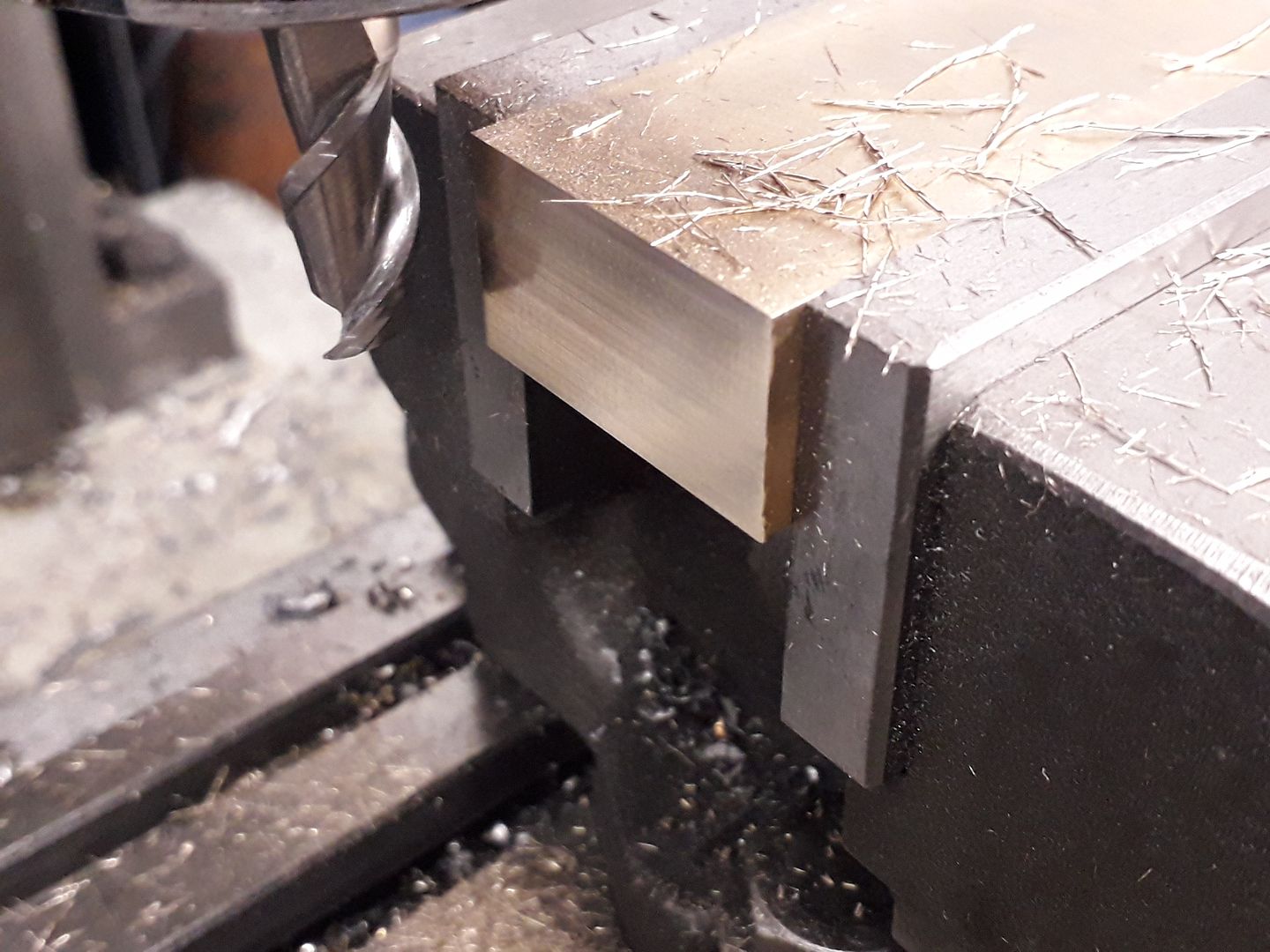
          I did not have a block of bronze large enough for the valve block so silver soldered a small piece on and after milling to overall size added a couple of counterbored cap head screws to keep both part stogether during subsequent silver soldering. A carbide cutter with high helix angle designed for aluminium also cuts other non ferrous metals well

          Starting to look a bit like the engine in the photo.

          J

          #448885
          JasonB
          Moderator
            @jasonb

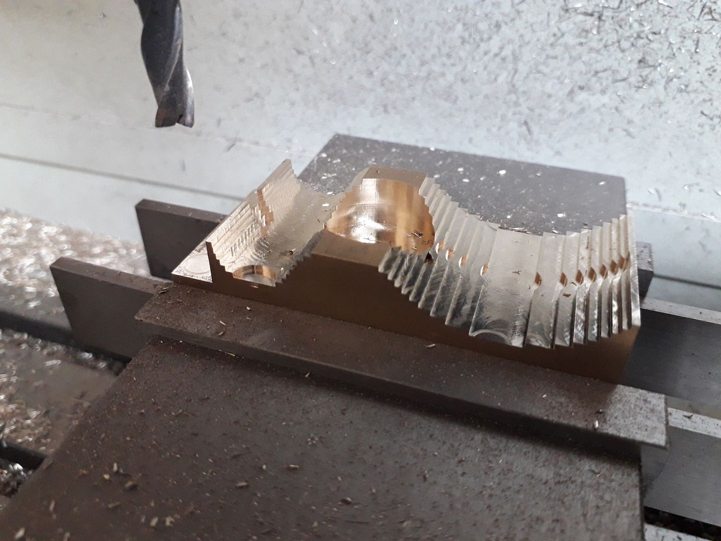
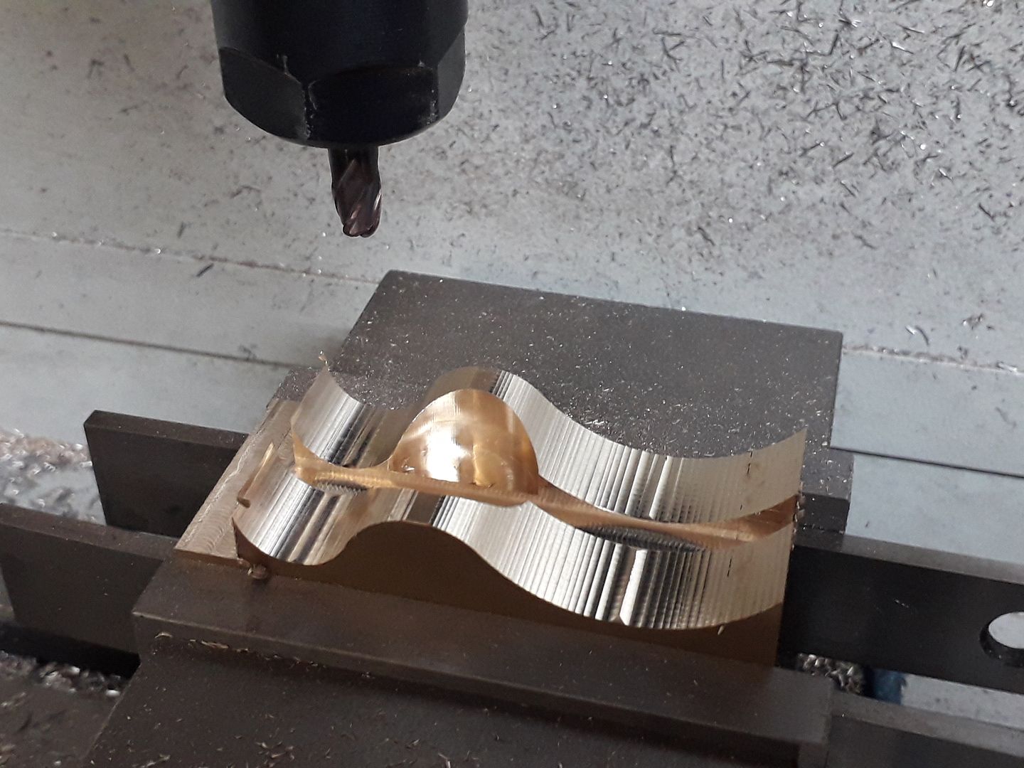
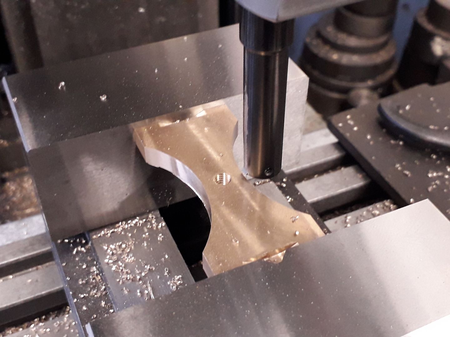
            Next job was to shape that block of bronze in the previous photo into something a bit more shapely for which I used the CNC though it could also have been done on a manual mill but not as quickly.

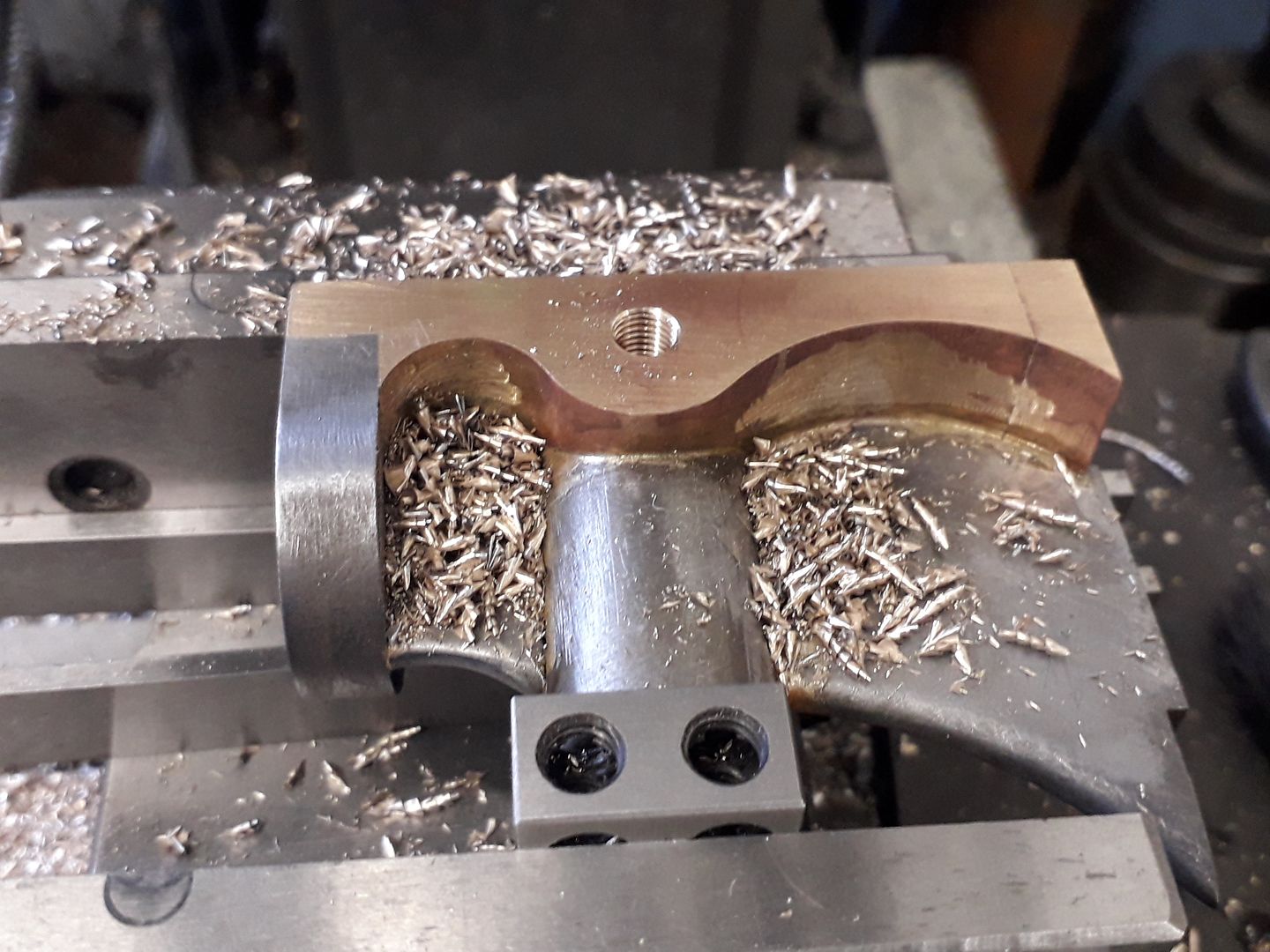
            This video shows the 4 separate operations. First is boring the hole for the central pivot boss , then the adaptive cuts which basically rough out the shape leaving 0.5mm to still come off both done with a 3-flute 6mm cutter followed by cleaning up the top rebate and cutting the central slot with a 4mm cutter and finally the finish contour with a 6mm ball nose cutter.

            Still of the part after the first two operations

            And this one is when CNC machining complete

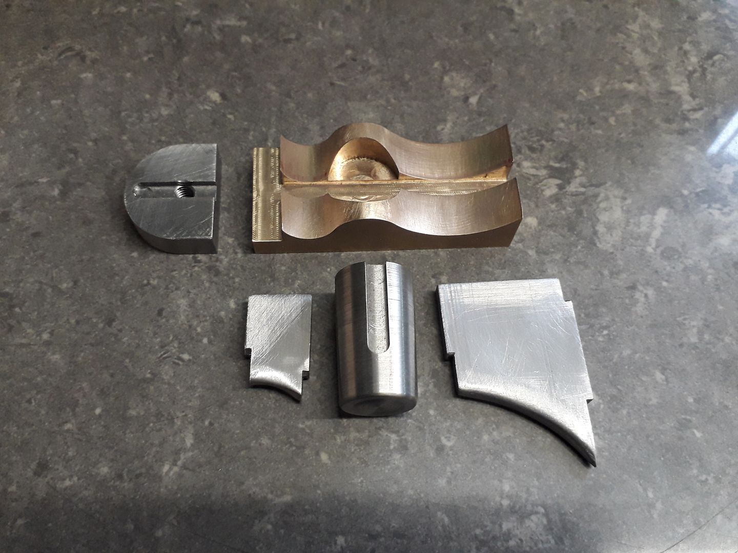
            A little bit of filing soon removed the facets left by the mill though if I had let it run longer I could have used a shallower stepdown but as it is to represent a casting the odd bit of handwork gives a better feel. I also made the two stiffening webs from offcuts of 5mm plate, 8mm for the top piece and turned a draft angle on the pivot boss. Here are all the parts before silver soldering.

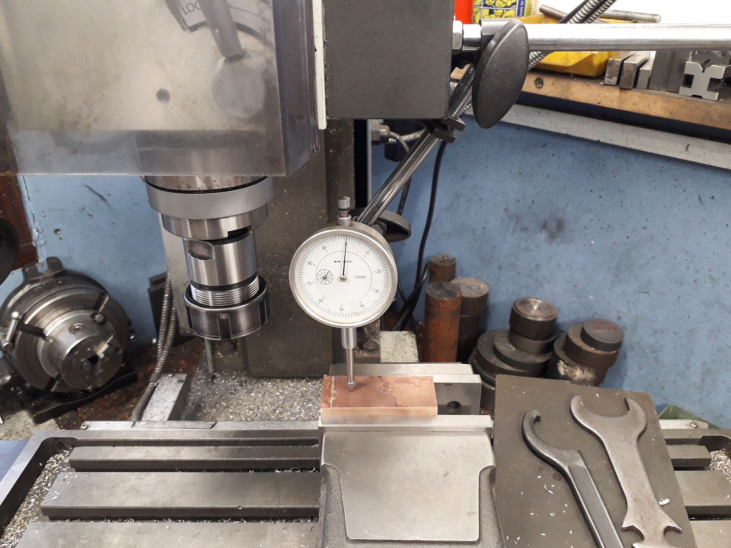
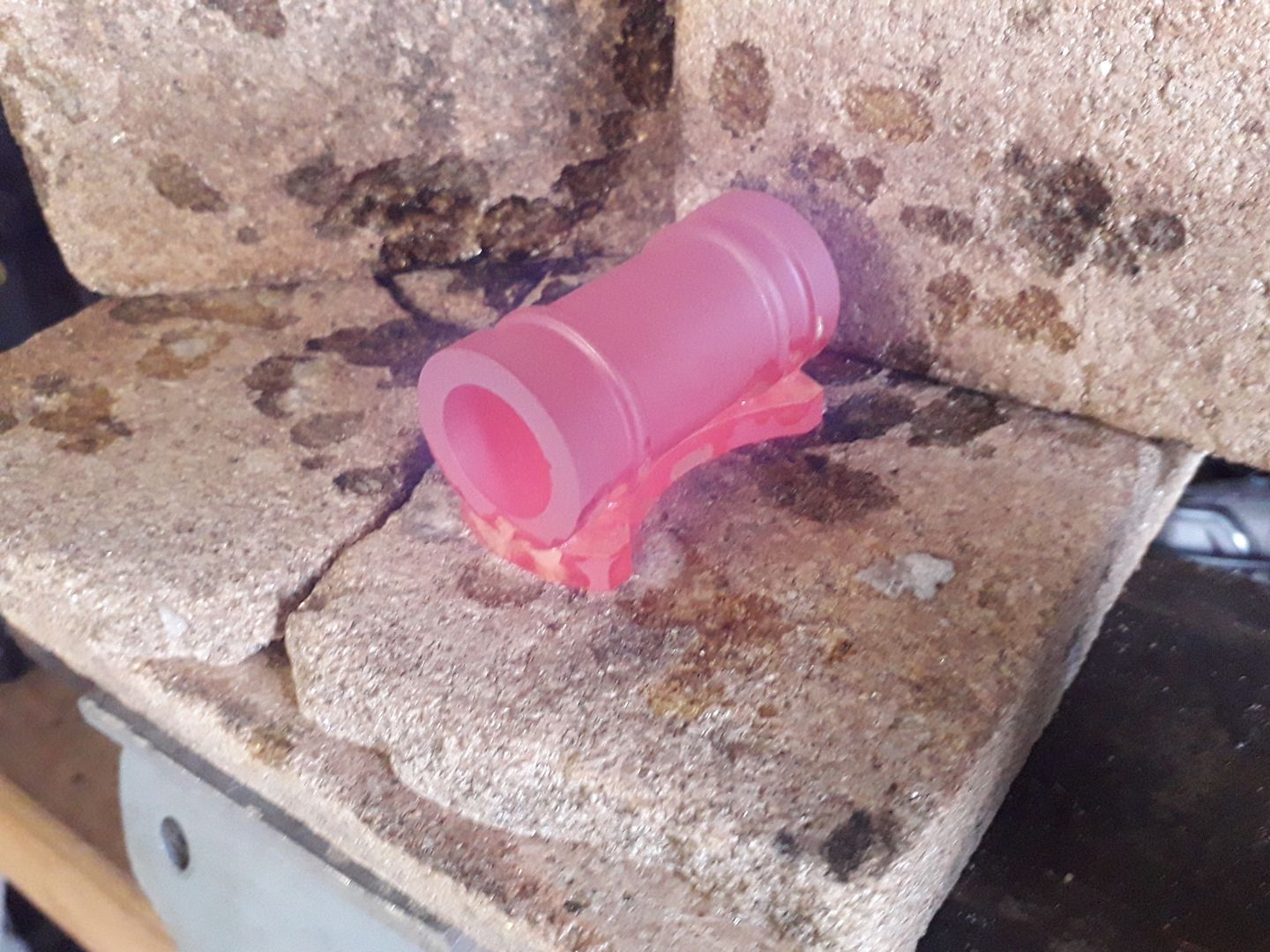
            Once cooled and pickled to clean it up the valve block was clocked level in the mill vice as there was no flat surface below to sit on parallels. You can also see that the solder I used to add on the extra bit of bronze had melted during the assembly soldering so just as well it was also screwed in place.

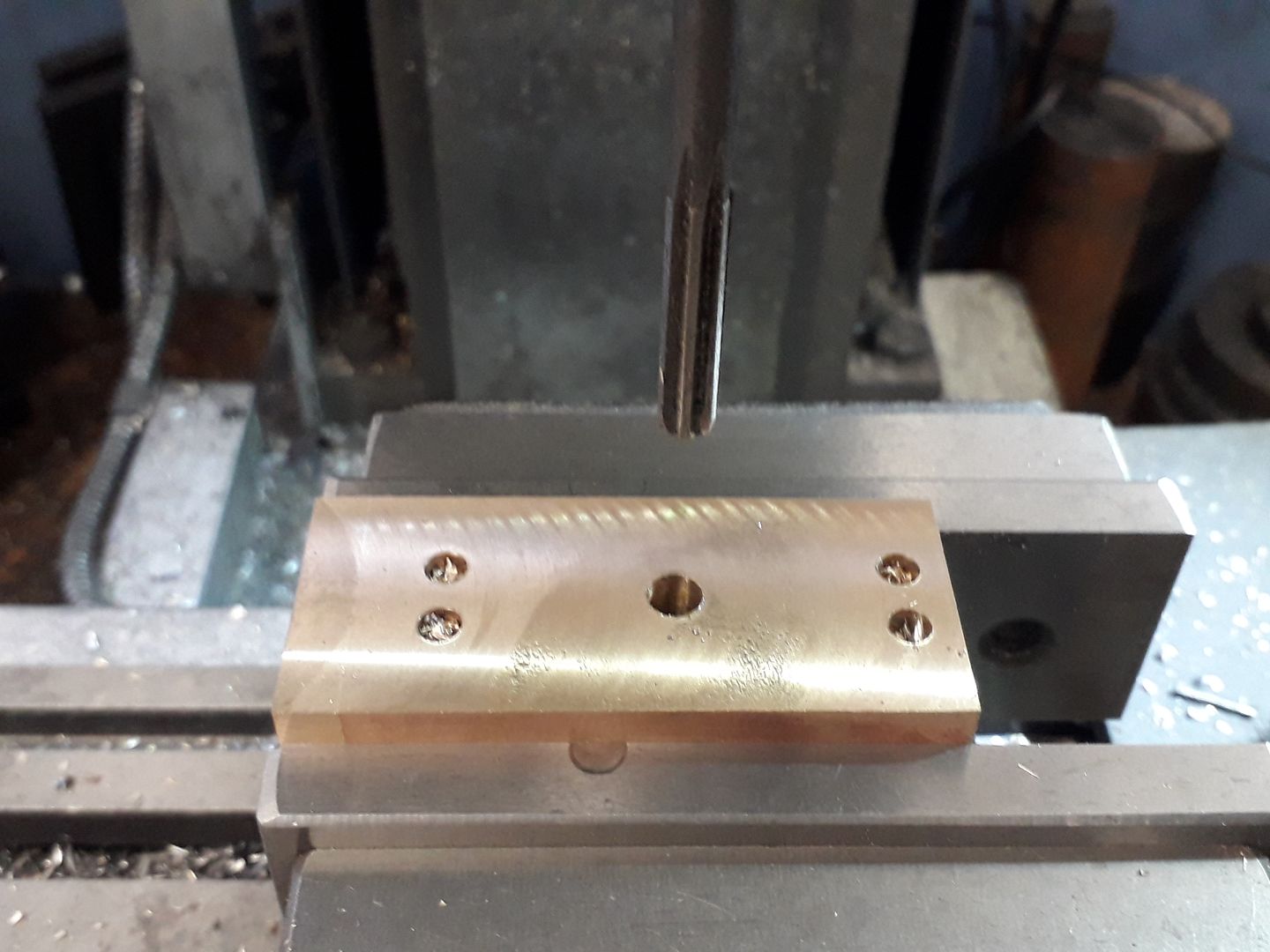
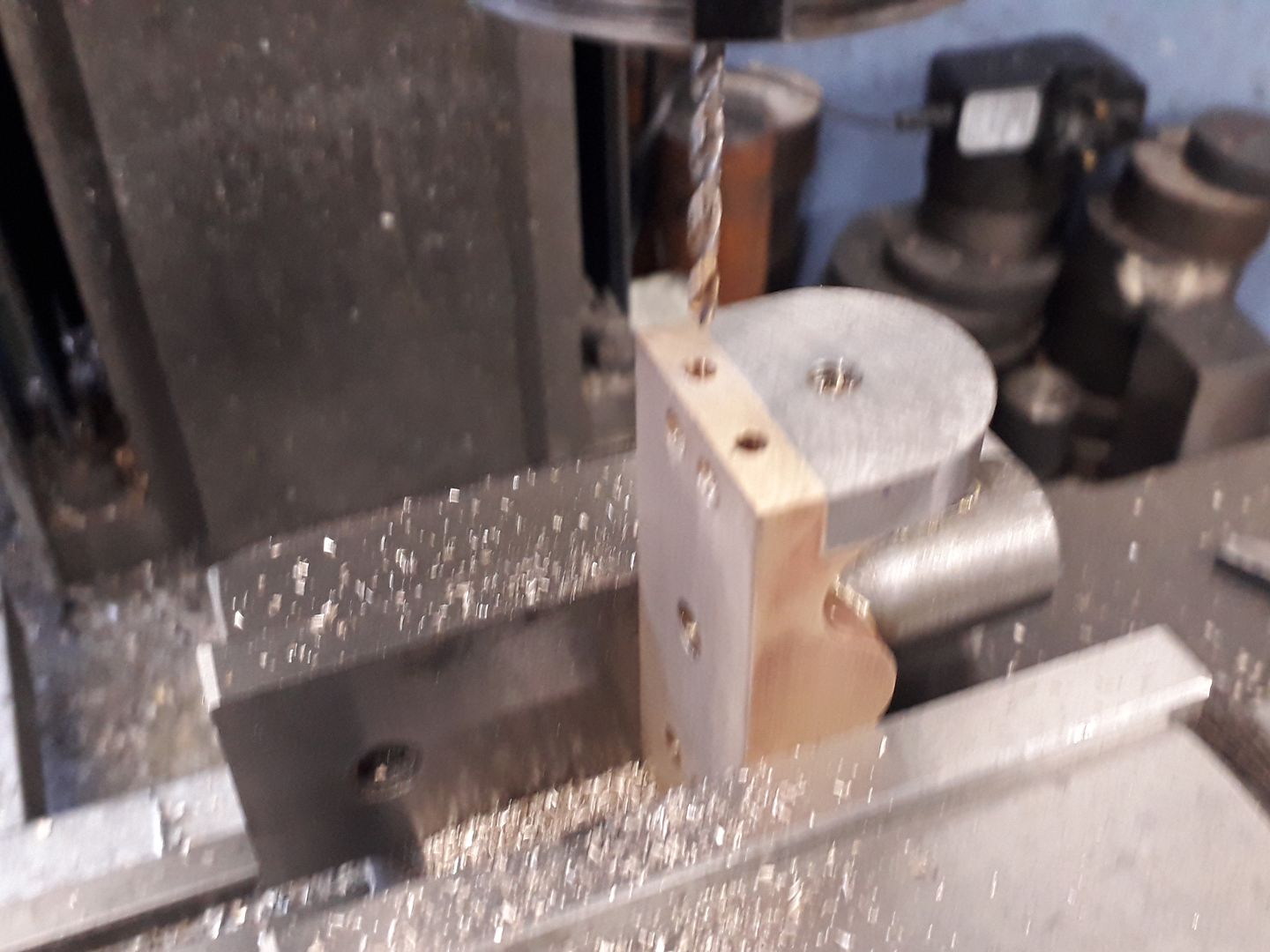
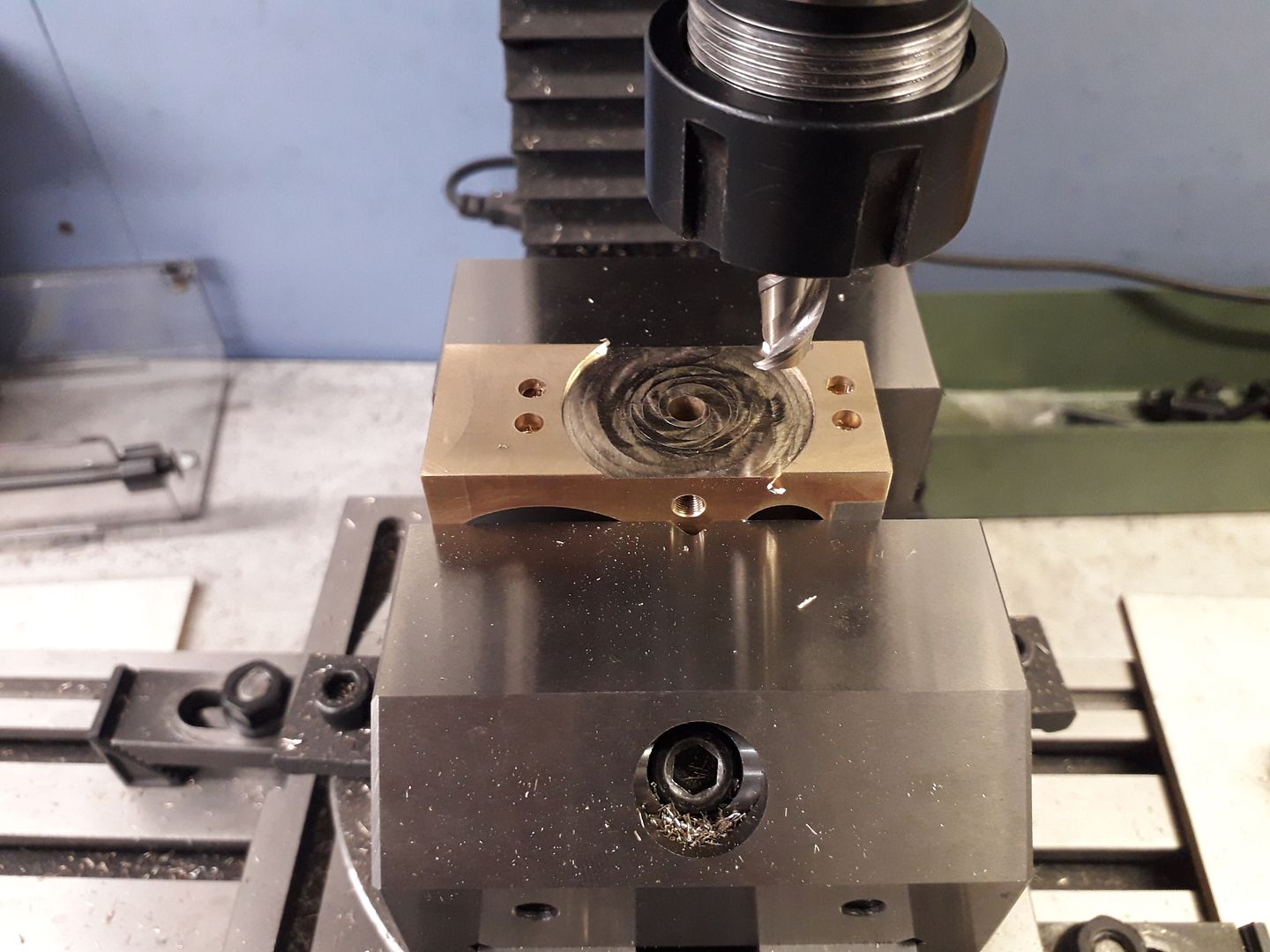
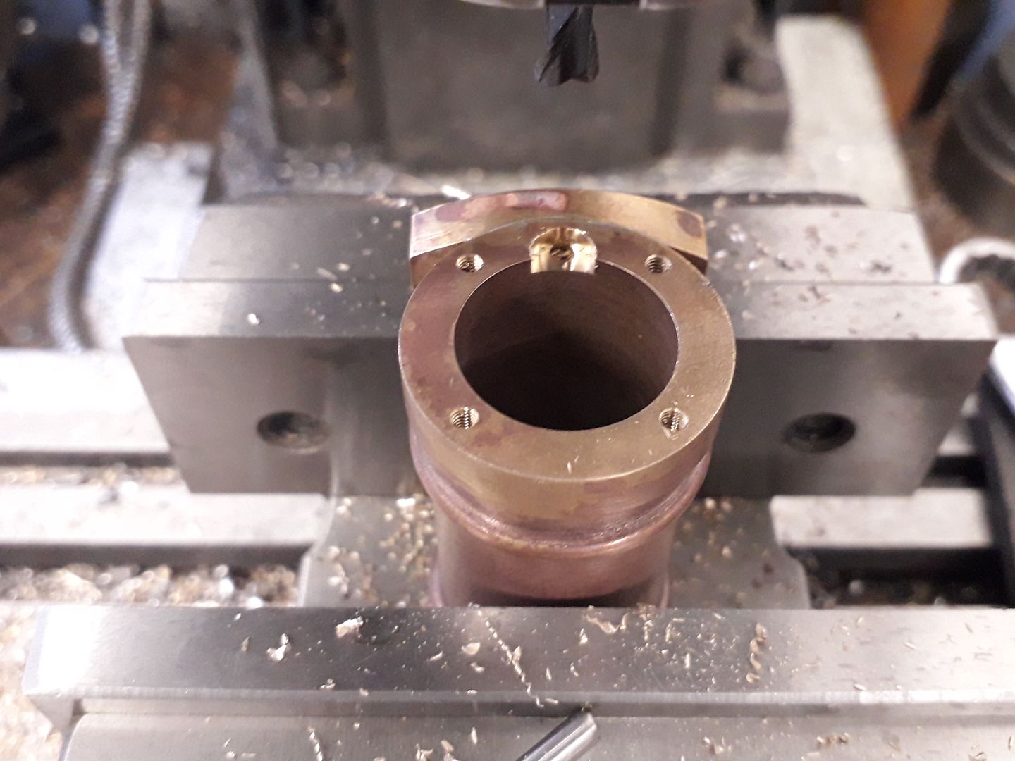
            After skimming the port face back to final dimension the four ports were drilled and a central hole drilled and reamed right through for the pivot. Not obvious from the photos but I deviated on the traditional sizing of port and cylinder holes by making the port ones larger, this is supposed to help the cylinder fill and empty as the full area of the cylinder port is open earlier and closes later, more details on this web page

            The ports were then extended down to where the inlet and exhaust fittings would be with long 3mm holes, the ends of these were later plugged with small bronze plugs loctited into place. Sorry for the fuzzy photo.

            The two tapped holes for inlet and exhaust were added, M5 x0.5 for the inlet and M6 x 0.75 for the exhaust

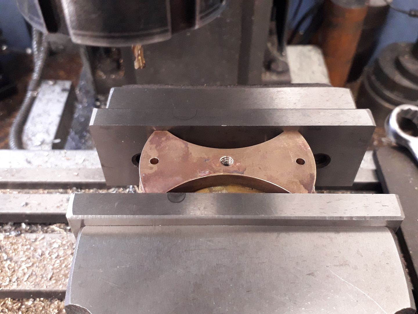
            Finally with the part held in a vice on top of the rotary table a 1mm deep recess was milled around the pivot which reduces friction and makes it easier for the cylinder to seat, also less surface to lap which makes the process go faster.

            #448945
            Ron Laden
            Participant
              @ronladen17547

              Nice work Jason and interesting especially the link to the valve timing do you think I would benefit from that or leave as standard.
              #448946
              nigel jones 5
              Participant
                @nigeljones5

                very nice – any idea how much the PS item is – must be over priced if its been there so long?

                #448969
                JasonB
                Moderator
                  @jasonb

                  Ron, may not be worth it on a single acting engine but I'll take a look at tehdrawings a bit later and see.

                  Fizzy, price is on their site at £1250, does not give a size but I doubt it is much bigger than mine.

                  #449487
                  JasonB
                  Moderator
                    @jasonb

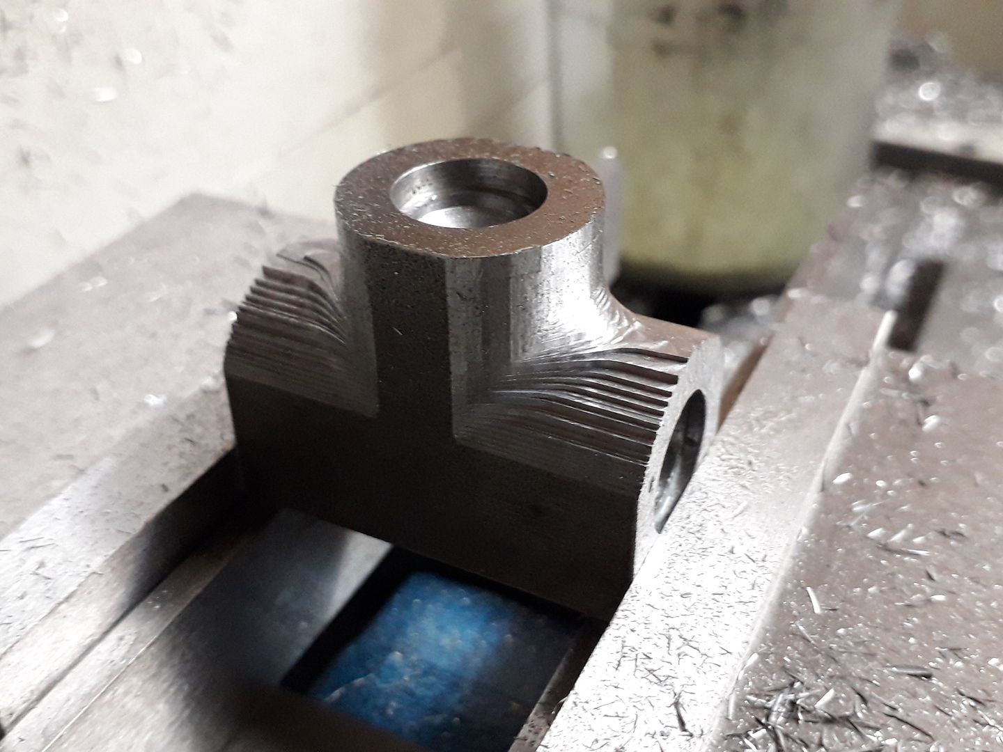
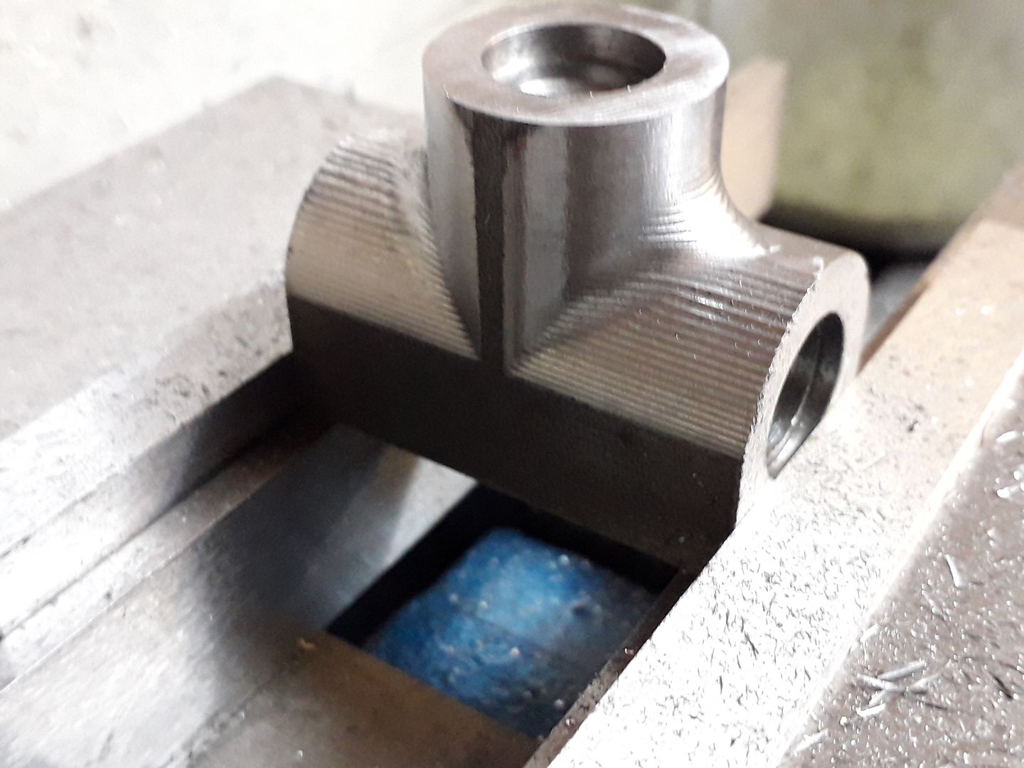
                    I decided to use the CNC again to machine the "tee" at the top of the column as it could easily form the fillets where the vertical part joined the horizontal, this is it after the initial adaptive cut to remove the majority of the waste material.

                    and after a final contouring cut, the steps look larger than they actually are and were quickly blended with just a needle file.

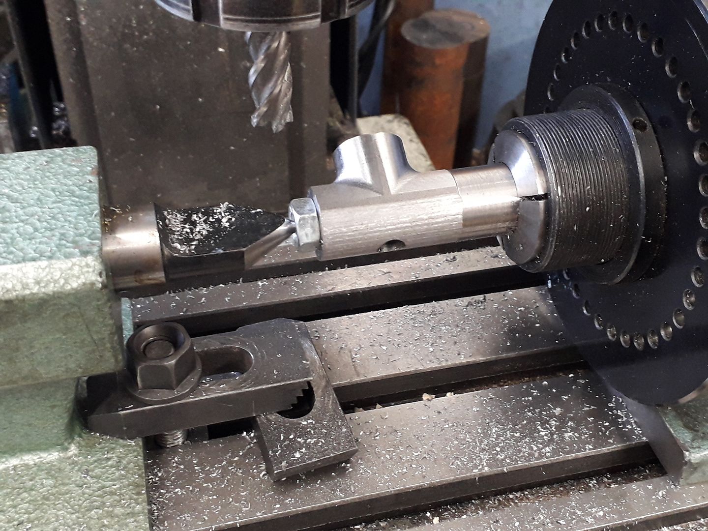
                    For what would be the top curve I simply mounted the part on the spin indexer and took cuts at 10degree intervals. You can also just see a 7mm hole that will have a bush bonded in on final assembly to take an oil cup which also allows access for an allen key so that the tee can be attached to the top of the column with a reduced head cap head screw.

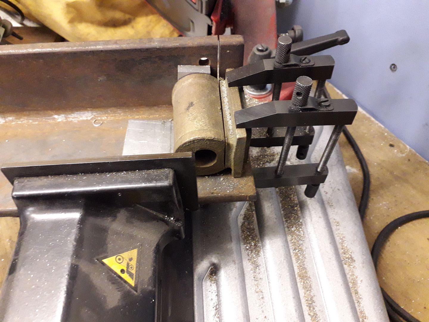
                    You may know that I'm not really a fan of model locos so having a few cylinder castings for them I decided the best thing to do was to chop them up :mischief:

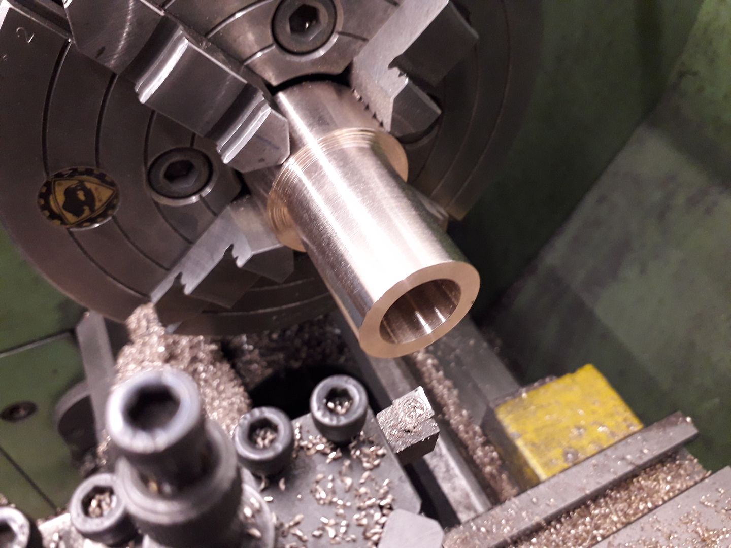
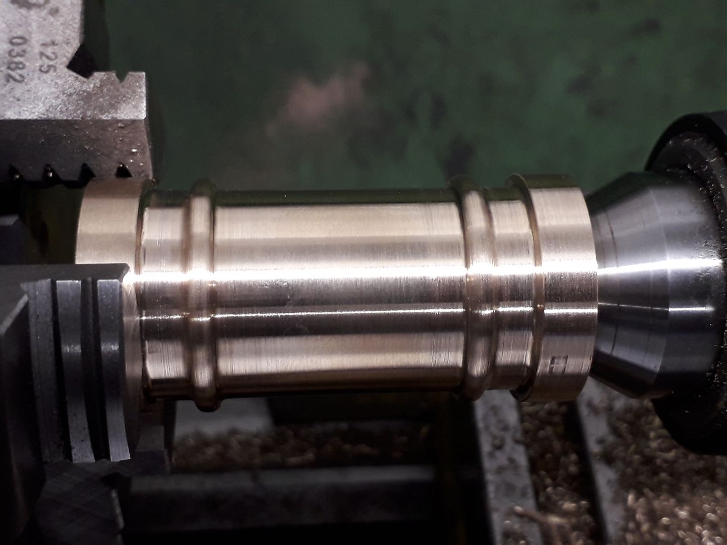
                    The round but was cleaned up to form the main cylinder

                    Then a 2mm diameter grooving tool was used to add some shape to the outside

                    Followed by a form tool and a little file work to produce the decorative beads.

                    Finally a flat was machined to give a mating surface for the port block to be silver soldered to, the ends were left round as they project slightly beyond the port block.

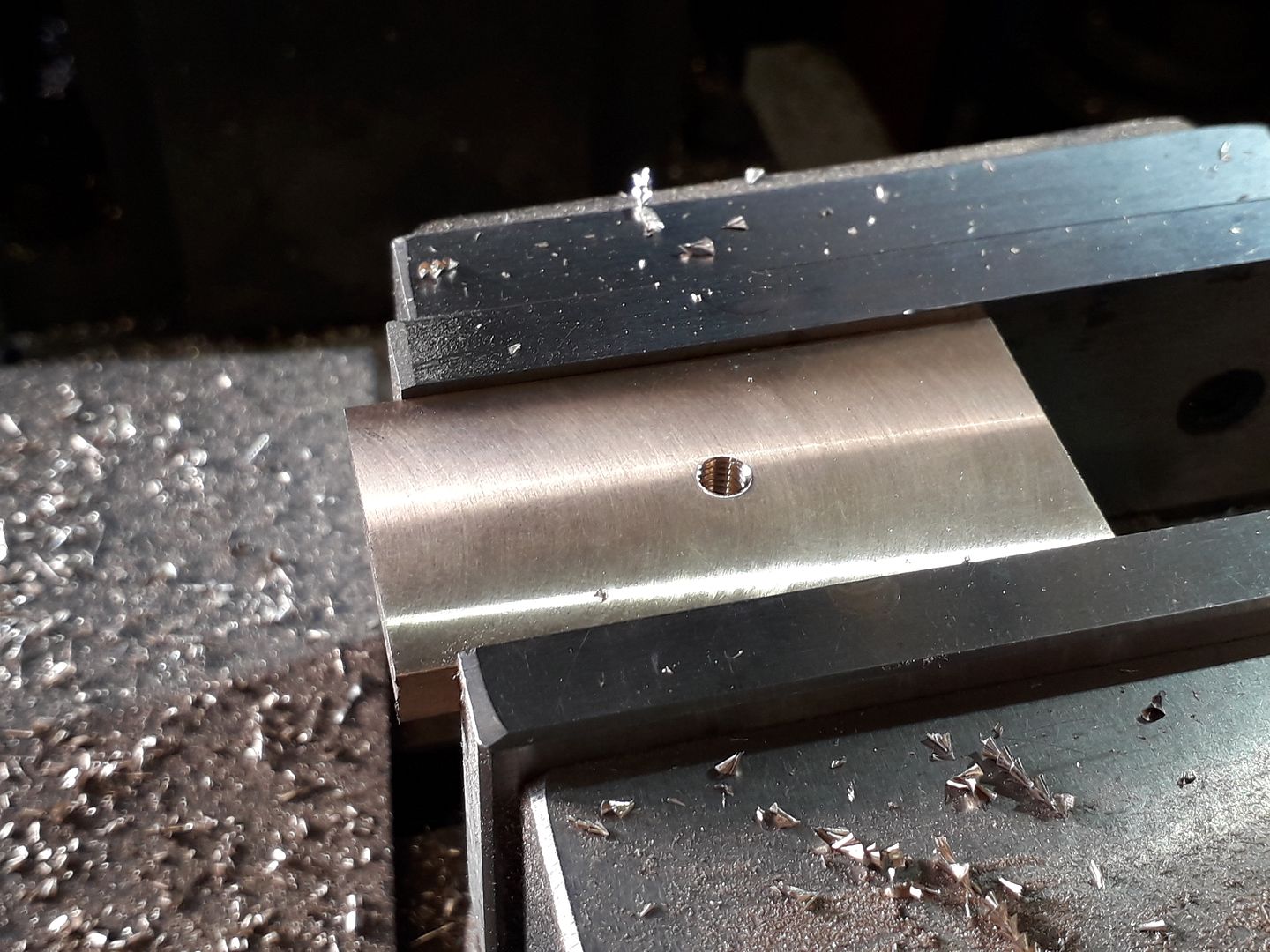
                    The other piece of bronze cut off from the cylinder casting was cleaned up into a rectangular shape and a M6 hole tapped for the pivot rod.

                    Two recesses were cut in the ends to take the bits that were left round on the cylinder part

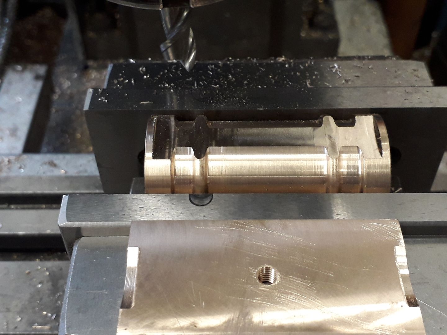
                    While the boring head was in the mill the two sides of the block were given their concave shape.

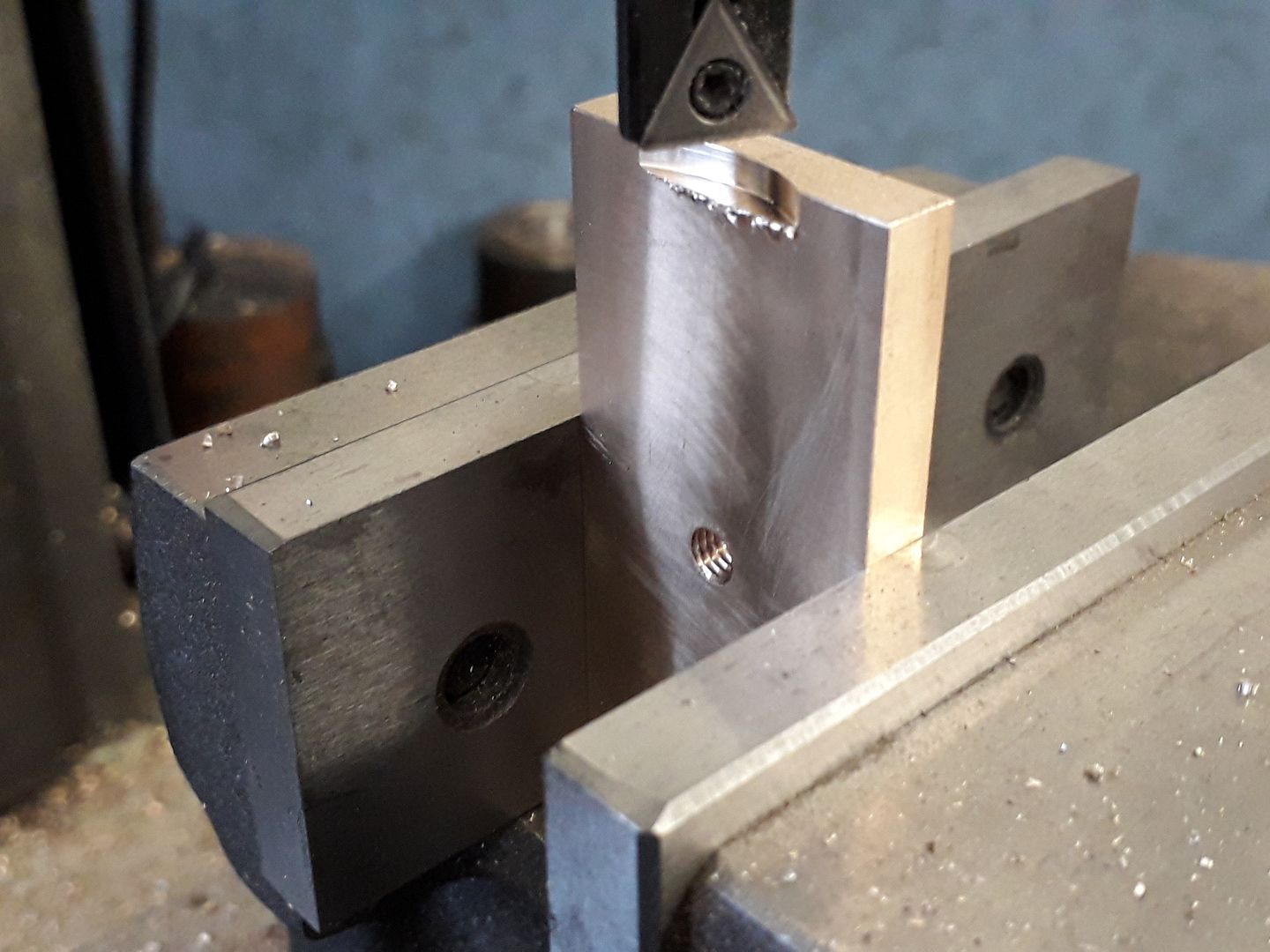
                    Lastly the M6 hole was used to hold the work to round the top and bottom to 30mm radius.

                    #450819
                    JasonB
                    Moderator
                      @jasonb

                      The two parts of the cylinder were then silver soldered together

                      After half an hour in the pickle steam passages were drilled down vertically from each end and a "D" shaped recess milled so that the steam/air could get to the end of the bore once the cylinder covers were in place.

                      Two holes were then drilled into the port face to link up with the ones from the ends of the cylinder.

                      The cylnder covers were quite straight forward turnings from cast iron bar, here the spigot on the bottom one has been recessed to clear the nut retaining the piston onto it's rod.

                      And this shows the typical long neck on the other cover that guides the piston rod being threaded M10 x 1 for a gland nut.

                      The piston, rod and big end were all simple parts like I have shown before so no pics this time.

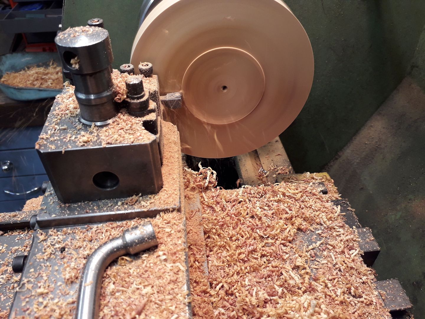
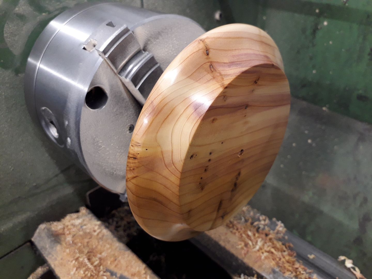
                      A piece of Yew was cut from a trunk I planked a few years ago and have had seasoning that came from a friend of my fathers was mounted onto a screw chuck held in the lathe chuck and roughed out with a CCGT insert.

                      Then shaped with traditional wood turning tools and then given a couple of coats of Melamine lacquer.

                      #450822
                      Ron Laden
                      Participant
                        @ronladen17547

                        Nice work Jason as usual, I noted that the bottom cylinder cover has a recessed spigot to allow for the piston retaining nut. I wondered is the piston threaded and then the nut acting as a lock nut or is the piston rod plain but with a shoulder and the nut pulling the piston onto a shoulder.

                        #450826
                        JasonB
                        Moderator
                          @jasonb

                          Ron, I usuallt reduce the piston end of the rod and thread for about 2/3rds the length of the spigot. I this case the end of the 5mm dia rod was reduced to 4mm for a length of 11mm and 7mm of that threaded M4. The piston is drille dpart way 4mm and the remainder threaded M4. I usually also counterbore the piston to take part of the nut

                          When put together the rod is screwed into the piston and the unthreded length helps keep things concentric, the nut locks the two together.

                          #450845
                          Ron Laden
                          Participant
                            @ronladen17547

                            That's neat Jason I can see how it keeps the piston/rod true, if threaded only and fitted dry do the pistons tend to unscrew in running.

                            #450847
                            JasonB
                            Moderator
                              @jasonb

                              I suppose there is a chance of them coming off in that case.

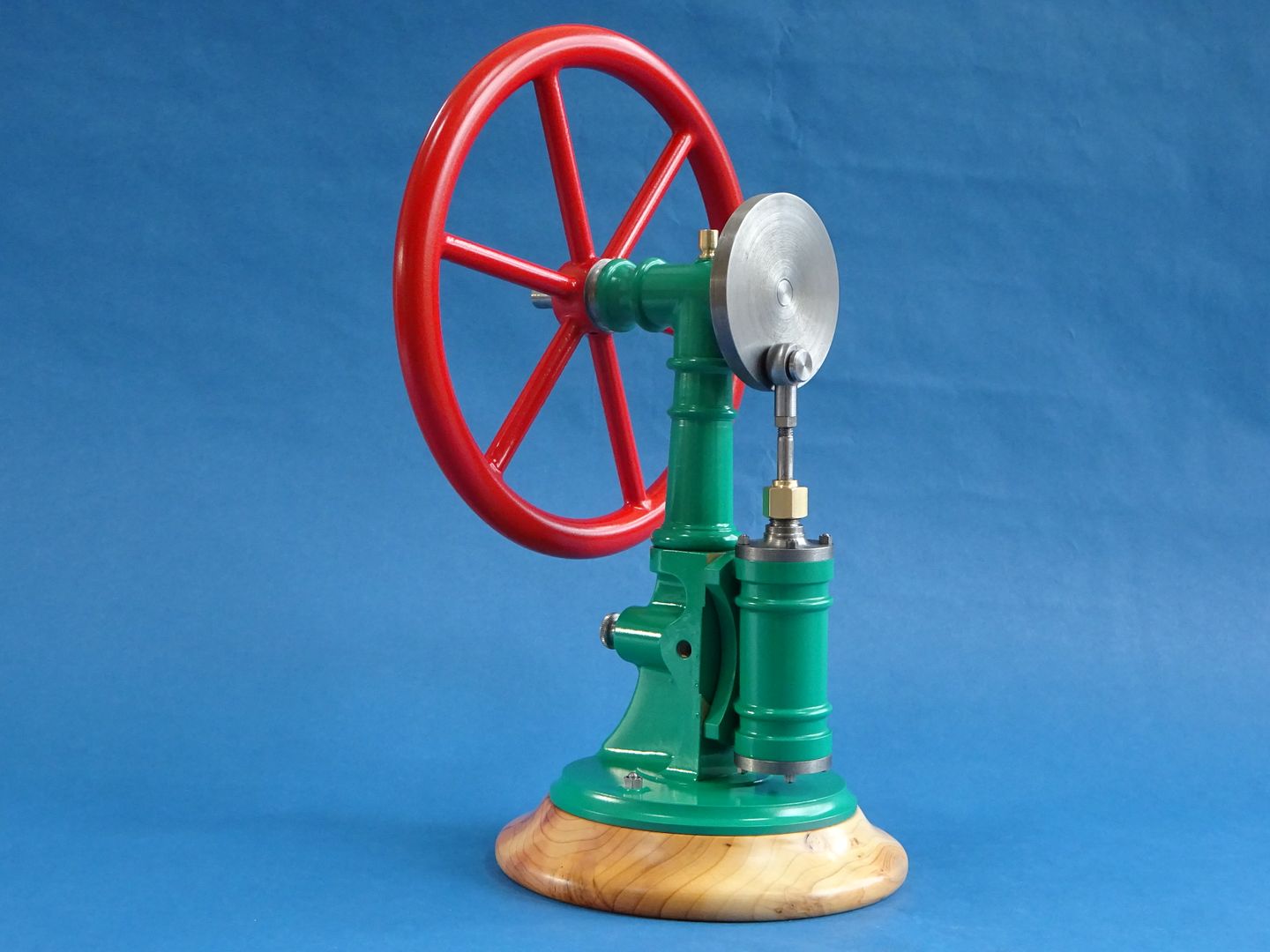
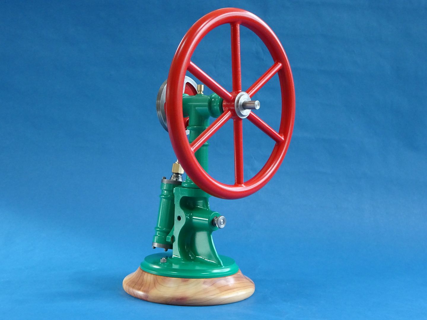
                              EDIT Just realised I had not put up the photos of the completed engine

                              Edited By JasonB on 07/06/2020 10:19:49

                              #478286
                              PatJ
                              Participant
                                @patj87806

                                Great work.

                                It looks fantastic, as do all your engines.

                                I have admired that engine for a long time.

                              Viewing 14 posts - 1 through 14 (of 14 total)
                              • Please log in to reply to this topic. Registering is free and easy using the links on the menu at the top of this page.

                              Advert

                              Latest Replies

                              Home Forums Stationary engines Topics

                              Viewing 25 topics - 1 through 25 (of 25 total)
                              Viewing 25 topics - 1 through 25 (of 25 total)

                              View full reply list.

                              Advert

                              Newsletter Sign-up