Precision pendulum techniques

Advert

Precision pendulum techniques

Home Forums Clocks and Scientific Instruments Precision pendulum techniques

Viewing 25 posts - 201 through 225 (of 502 total)
  • Author
    Posts
  • #637249
    Michael Gilligan
    Participant
      @michaelgilligan61133

      Oh dear

      Advert
      #637250
      SillyOldDuffer
      Moderator
        @sillyoldduffer
        Posted by S K on 11/03/2023 19:11:12:…

        For electromagnetic impulsing, I've thus far only seen a more-or-less digital approach: The coils are simply turned on and off via a digital signal, with little other control except timing and sometimes magnitude. But a proper electronic filter could soften the blow in a more controlled fashion. Or, even better, a DAC and associated circuitry could implement an arbitrary programmable force curve.

        Either way, it's not clear to me that anything much different than a pseudo-Gaussian is worthwhile, but being able to control it at a fine level sounds interesting and possibly beneficial.

        Does this make sense?

        Yes, apart from pseudo-gaussian. I think that's a form of curve, but exactly what and why?

        I've thought of filtering the digital pulse to my electromagnet, but not tried it. The resulting magnetic field is already filtered by the magnet's inductance, but I've not measured it. Must put a Hall Sensor on my scope and have a look. Hadn't thought of a DAC, (how fast it would it need to be?), but I have a waveform generator that can shape pulses to test the idea.

        I've attempted a soft impulse by having the electromagnet some distance from the bob, because the field weakens quite rapidly with distance. The impulse is fired soon after the bob passes dead centre, and stops before the bob has travelled far. (Not done the sums!) Then I adjust the pulse length down until the pendulum gets just enough energy to keep going. I've not felt the need to experiment with deliberately shaped pulses because statistical analysis of the log data doesn't show much sign of impulse disturbance. (That the pendulum is disturbed by more powerful pulses does show up in the stats.) I guess a low Q pendulum would benefit more from a shaped impulse more than a high Q job. Low Q needs more energy, making it likely that the pendulum has to be thumped. On the other hand, a high Q pendulum could be more sensitive…

        The combinations feel endless!

        Dave

        #637257
        david bennett 8
        Participant
          @davidbennett8

          I have very little knowledge of the hi-tech electronic devices that are being used here to test experimental pendulum systems.

          I can see that the testing system must be more accurate than the tested system, and that the results look rather messy.

          Have these hi- tech testers been applied to known high performance clocks (such as synchonomes ) in order to see how  messy the results look?

          I thought Dave was trying for a high performance clock, not a world beater.

          dave8

          Edited By david bennett 8 on 11/03/2023 22:34:57

          #637258
          S K
          Participant
            @sk20060

            A true Gaussian (a "bell curve" ) has infinite tails, which you wouldn't want, so it would need to be a modified one that starts and stops with zero force. Perhaps a modified Gaussian-like profile without the infinite tails is not perfect for this, but it has got to be pretty close. You want it to start almost imperceptibly, grow smoothly to a peak, and then decline back to zero in the same way.

            P.S., that darned insertion of a winking smiley when you type " followed by ) is so irritating!


            Edited By S K on 11/03/2023 22:35:43

            #637261
            duncan webster 1
            Participant
              @duncanwebster1

              We could call it a raised cosine, as someone mentioned before, either on this thread or one of the others.

              #637265
              S K
              Participant
                @sk20060
                Posted by duncan webster on 11/03/2023 22:39:24:

                We could call it a raised cosine, as someone mentioned before, either on this thread or one of the others.

                Ah, good. Thanks for that.

                #637274
                John Haine
                Participant
                  @johnhaine32865

                  Robert Matthys and Ned Bigelow both experimented with sinusoidal drive. A moving magnet transducer attached to the pendulum connected in an oscillator circuit with an op amp. IIRC there's a chapter on it in Matthys' book.

                  Edited By John Haine on 12/03/2023 08:06:20

                  #637328
                  Tony Jeffree
                  Participant
                    @tonyjeffree56510
                    Posted by John Haine on 12/03/2023 08:06:00:

                    Robert Matthys and Ned Bigelow both experimented with sinusoidal drive. A moving magnet transducer attached to the pendulum connected in an oscillator circuit with an op amp. IIRC there's a chapter on it in Matthys' book.

                    Edited By John Haine on 12/03/2023 08:06:20

                    Isn't the drive entirely controlling the pendulum frequency at that point?

                    #637332
                    John Haine
                    Participant
                      @johnhaine32865

                      No, the pendulum is the resonator. Like the crystal in a crystal oscillator.

                      #637333
                      SillyOldDuffer
                      Moderator
                        @sillyoldduffer

                        Posted by david bennett 8 on 11/03/2023 22:27:09:

                        Have these hi- tech testers been applied to known high performance clocks (such as synchonomes ) in order to see how messy the results look?

                        I thought Dave was trying for a high performance clock, not a world beater.

                        Yes, but not by me, in various ways, and as far as I know the data isn't available. I've thought of building a John Haine style clock – long rod, heavy pendulum, Helmholz coils, bolted to wall etc, simply so I can measure it for comparative purposes.

                        I'm certain from reading books that measuring a pendulum accurately reveals 'noise', i.e the period is almost never spot on, but beats scatter more-or-less evenly about an average, or move consistent with environmental change, notably temperature and air-pressure. Many other sources of noise. Vibration due to traffic or seismic activity, the house moving with temperature, and exotics, such as Invar being unstable at the molecular level, or micro-gravitational changes due to ground water moving with the tide.

                        Although I expect to find noise, I don't have a good measure of how good or bad my clock is relative to better made examples.

                        I'm aiming for a world beater in the sense I'm comparing my 'made with modern parts' clock with a Shortt-synchronome of 1921. Be good if my clock performed better than a Shortt, but I'm a long way off achieving that!

                        A more cheerful test result today. A few days ago I reported a laser beam bounced off by tripod detected movement. The tripod was on a dining table, so I repeated the test by putting the tripod on the floor, which is teak parquet on concrete. I also rearranged the beam to amplify movement more. This time I couldn't see any movement in the remote dot.

                        So, the tripod is stiffer than my dining table. Interesting that a 40g bob swinging about 15mm shakes a two-man lift wooden table! The reason is the table top is sat on four long and relatively wobbly legs.

                        Dave

                        #637347
                        duncan webster 1
                        Participant
                          @duncanwebster1

                          I've got a triple fusee bracket clock which runs if you put it on a concrete floor, but not if it's up on furniture. It obviously needs some attention, but it shows the effect of lack of rigidity in the support.

                          #637352
                          Martin Kyte
                          Participant
                            @martinkyte99762

                            Same thing with longcase clocks standing on carpet. My old mate Barrie got caught out with testing a known runner of a long case movement to sort the strike out and it just would not run. Eventually worked out it was the ancient clock horse standing on carpet to be the cause. The thing that alerted him was the clock weights had started swinging.

                            Now there is a thought. If you attach a second pendulum to the suspension frame of similar period to the clock pendulum would that provide a sensitive test for rigidity. You could perhaps measure the time constant for increase in amplitude. It would only really be a comparative measure but after all you just want to know if you are heading in the right direction. Sort of wobble integrator.

                            regards Martin

                            Edited By Martin Kyte on 12/03/2023 14:27:35

                            Edited By Martin Kyte on 12/03/2023 14:28:26

                            #637364
                            John Haine
                            Participant
                              @johnhaine32865

                              Or attach a second identical pendulum permanently to swing in antiphase and balance the clock…

                              #637374
                              Martin Kyte
                              Participant
                                @martinkyte99762
                                Posted by John Haine on 12/03/2023 16:40:47:

                                Or attach a second identical pendulum permanently to swing in antiphase and balance the clock…

                                Well yes but I was thinking of a simple way for Dave to see if he’s heading in the right direction. Not sure he has room for two pendulums.

                                regards Martin

                                #637386
                                S K
                                Participant
                                  @sk20060

                                  So Matthys explored a continuous drive approach using clipped sine wave (apparently first tried in 1960). The notion is to continuously restore the lost energy. So at the extremes of the swing, the restoring force should be zero, and at BDC, when the speed and hence air resistance is at its maximum, the restoring force should be at its peak.

                                  I don't understand the original motivation for clipping, though – it seems plainly contrary to what is desired, as Matthys eventually points out. Also, while continuous drive seems to make sense at some level, it's long been known that the ideal time to impulse (at least for a brief one) is at BDC. Continuous drive would also have to be quite precise about its phase relationship, or near the extremities it may start pushing when it should still be pulling and vice versa.

                                  Matthys eventually comes to the conclusion that continuous drive is not ideal, and that a brief impulse at BDC is likely superior. He also expresses concern about the stability of the drive, which goes back a long way in the earliest attempts at electromagnetic drive. He did mention that a continuous drive could at least be more gentle over its profile than a shorter one at BDC.

                                  My thought is that a raised-cosine drive or similar profile concentrated at BDC is likely to be superior to a "digital" one, as that "twanging" – the shock of a sudden sharp impulse that some here have observed – would likely be lessened.

                                  #637391
                                  SillyOldDuffer
                                  Moderator
                                    @sillyoldduffer
                                    Posted by Martin Kyte on 12/03/2023 16:56:01:

                                    Posted by John Haine on 12/03/2023 16:40:47:

                                    Or attach a second identical pendulum permanently to swing in antiphase and balance the clock…

                                    Well yes but I was thinking of a simple way for Dave to see if he’s heading in the right direction. Not sure he has room for two pendulums.

                                    regards Martin

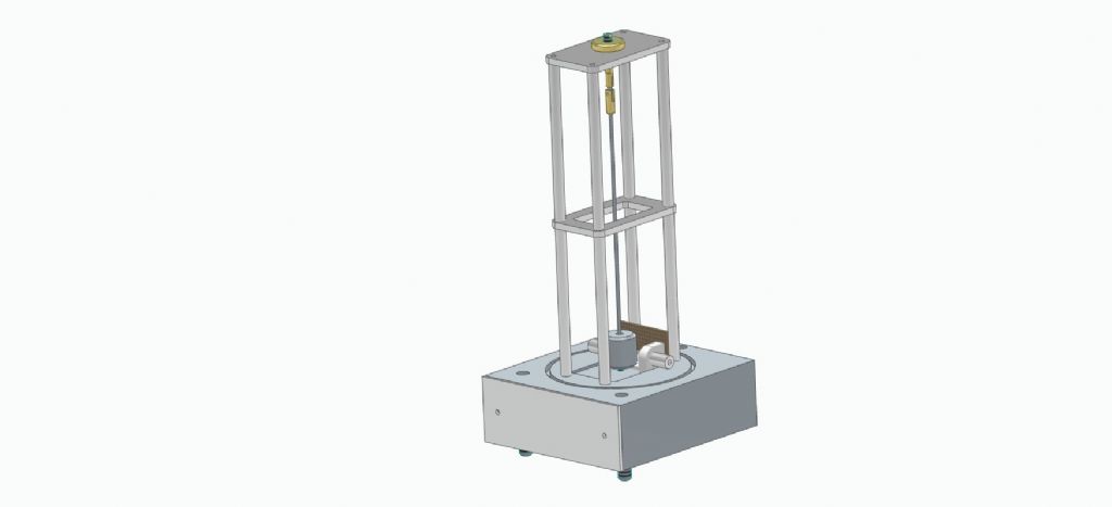
                                    I don't! This is the latest design:

                                    mk4-4passy.jpg

                                    Scale: about 300mm tall, the bob is 25mm diameter, the base 140 x 140mm.

                                    Dave

                                    #637393
                                    S K
                                    Participant
                                      @sk20060

                                      As I'm not intending to try for a "world beating" pendulum-based system, and because I'm motivated to learn more about machining, I've been musing about developing some sort of "improved" mechanical impulsing technique.

                                      I happen to have a small servo that purportedly can be set to apply no more than a preset maximum torque. That's not what I want, though: I'd like to apply a varying torque, e.g. in a raised-cosine. If the baud rate is high enough, perhaps a continuously-varying torque could be approximated just using the servo, though.

                                      I've also seen cam-based systems that can apply varying torque, but they are not adjustable without cutting a new cam. In combination with a programmable-torque servo driving the cam, perhaps they could be made adjustable, but it feels like a fixed cam would inevitably have to be redesigned several times and perhaps never be quite right without some insane math to help figure out the profile.

                                      The nice thing about a servo is that they are so easy to control. But another problem may by how to reduce the torque, as a servo may be too strong compared to the tiny amount of force needed. I guess a 1 out of n swing approach could mitigate that.

                                      I was also thinking about a lever made of thin spring steel that would soften the torque application by flexing (I saw something like this in an ancient clock patent). Perhaps an appropriately-designed spring like this could, in conjunction with a fixed-torque servo and a feedback loop (strain gauge, capacitive sensor…) could work.

                                      A voice-coil is another possibility, but it would require a more complicated drive circuit than a servo would. And at that point, you might as well make an electromagnetic drive anyway.

                                      (Also, because I like quirky, amusing things that might make someone else smile too, I was even thinking of making a little hand or finger that applied the impulse to the pendulum – hehe.)

                                      #637394
                                      S K
                                      Participant
                                        @sk20060
                                        Posted by SillyOldDuffer on 12/03/2023 18:06:31:

                                        I don't! This is the latest design:

                                        Unless you are completely satisfied with whatever residual horizontal movement is in the hinge area, why not add some cross-bracing in the direction of the swing?

                                        #637402
                                        SillyOldDuffer
                                        Moderator
                                          @sillyoldduffer
                                          Posted by S K on 12/03/2023 18:17:03:

                                          Posted by SillyOldDuffer on 12/03/2023 18:06:31:

                                          I don't! This is the latest design:

                                          Unless you are completely satisfied with whatever residual horizontal movement is in the hinge area, why not add some cross-bracing in the direction of the swing?

                                          I probably will, the pillars just need some small holes drilled in them to take wires I can tourniquet tight to cross-brace the verticals.

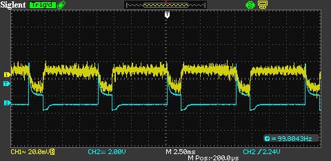
                                          On another tack, I've attempted to capture the shape of the magnetic pulse emitted by my electromagnet, which I expect is typical. Not brilliant because my Hall sensor (A1302) is deaf as a post but:

                                          sds00011.jpg

                                          The noisy yellow line is the strength of the magnetic field. The blue line is voltage across the magnet, which for the test is fed through a 220ohm resistor, so the blue curve is proportional to current.

                                          There's a sharp current spike when the pulse starts, and it drops rapidly as current flow is resisted by the magnet coil's inductance. When the pulse ends, the magnetic field collapses causing a negative going kickback, which, as can be seen, is clipped at about -0.6v by a protective diode across the coil.

                                          Field strength is proportional to the current flowing in the coil and how far away the bob is, and both change during the impulse. My maths is terrible, but should be possible to graph how the strength of the magnet field varies as the bob flies through it. My feeling is the two interact to soften the jolt, but I could be wrong!

                                          Dave

                                          #637411
                                          John Haine
                                          Participant
                                            @johnhaine32865
                                            Posted by S K on 12/03/2023

                                            I don't understand the original motivation for clipping, though – it seems plainly contrary to what is desired, as Matthys eventually points out. Also, while continuous drive seems to make sense at some level, it's long been known that the ideal time to impulse (at least for a brief one) is at BDC. Continuous drive would also have to be quite precise about its phase relationship, or near the extremities it may start pushing when it should still be pulling and vice …..

                                            There had to be some way to limit amplitude and the most direct way given the very low frequency was to allow the OP amp to clip. One could also nowadays do it digitally by sampling the waveform, rectifying the waveform in a processor, and use a multiplying DAC to adjust the loop gain. Matthys and Bigelow disputed the significance of the finite gain bandwidth product of the OP amp, I suspect it was negligible. I think the main problem with this method is that making the transducers is tricky.

                                            #637412
                                            S K
                                            Participant
                                              @sk20060

                                              Some form of low-pass filtering could help with those sharp edges, which can't be that great for the pendulum's performance.

                                              I'm far from an analog guru, but I suspect John would be able to provide some guidance, perhaps even a step towards that proposed raised-cosine profile.

                                              #637423
                                              david bennett 8
                                              Participant
                                                @davidbennett8

                                                Dave, sorry for my world beater assumption (I thought I read somewhere that you were seeking improvement by removing the escapement ) Good news on the stiffness though!

                                                dave8

                                                #637439
                                                david bennett 8
                                                Participant
                                                  @davidbennett8

                                                  Dave, how rigid is the impulse coil? Also, I presume it's battery powered?

                                                  dave8

                                                  #637494
                                                  SillyOldDuffer
                                                  Moderator
                                                    @sillyoldduffer
                                                    Posted by david bennett 8 on 13/03/2023 05:09:17:

                                                    Dave, how rigid is the impulse coil? Also, I presume it's battery powered?

                                                    dave8

                                                    No need to apologise for 'world beater', or anything else!

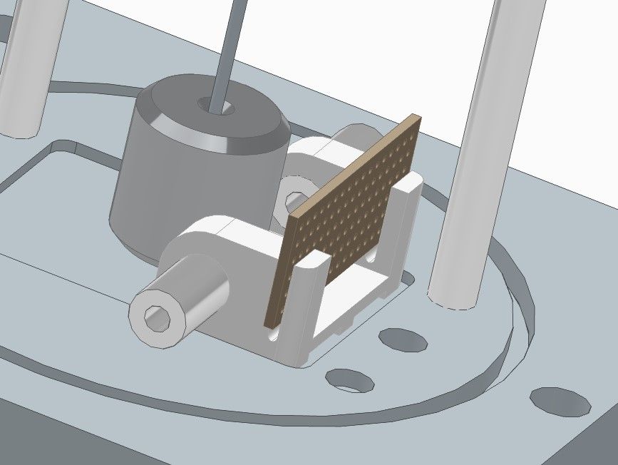
                                                    Great minds must think alike because I'm worrying about coil rigidity at the moment. In the Mk1 clock, the sensor and magnet carrier, which I'm now calling the 'chariot', was 3D-printed and hot-glued to the Aluminium base. The electromagnet is from a 5V miniature relay, of the type found in Arduino modules:

                                                    The Mk4 design is similar, except the chariot is going to carry the electromagnet, BME280 sensor, and IR beam electronics on a stripboard clipped at the back. The electromagnet is mounted side on to the bob, not underneath.

                                                    mk4chariot.jpg

                                                    The chariot was going to be glued, but I think a screw into the base would be better. The chariot slides along the base to adjust the position of the beam relative to the bob, before being clamped so the chariot will have to be slotted to .

                                                    Of concern are two design changes:

                                                    • I've increased the size of the mild-steel bob to about 90g rather than 40g, requiring a more powerful impulse.
                                                    • The base is now cast-iron rather than Aluminium. In the Mk1 the only ferro-magnetic object near the coil was the bob, now the base is too!

                                                    So the chariot and stripboard have to resist a horizontal pull towards the bob, and a down pull towards the base. I think the stripboard is likely to flex unless I reinforce it, and the 3d printed chariot is none to solid either. On the other hand, the impulse required to swing a 90g bob is small.

                                                    Now if only I had a big block of Brass to make a non-magnetic base! Being a cheapskate, I have to make do with what I've got.

                                                    Dave

                                                    #637503
                                                    Martin Kyte
                                                    Participant
                                                      @martinkyte99762

                                                      Just because the bob mass has doubled I don’t see why the losses should have doubled too. It would surprise me if the impulse has to be much bigger. It will be interesting to find out when you get things going. I think your chase for rigidity wherever practical is sound though.

                                                      regards Martin

                                                    Viewing 25 posts - 201 through 225 (of 502 total)
                                                    • Please log in to reply to this topic. Registering is free and easy using the links on the menu at the top of this page.

                                                    Advert

                                                    Latest Replies

                                                    Viewing 25 topics - 1 through 25 (of 25 total)
                                                    Viewing 25 topics - 1 through 25 (of 25 total)

                                                    View full reply list.

                                                    Advert

                                                    Newsletter Sign-up