Precision pendulum techniques

Advert

Precision pendulum techniques

Home Forums Clocks and Scientific Instruments Precision pendulum techniques

Viewing 25 posts - 76 through 100 (of 502 total)
  • Author
    Posts
  • #634558
    Howi
    Participant
      @howi
      Posted by SillyOldDuffer on 22/02/2023 08:59:45:

      I came across William Scolnik's website, describing his impressive clock. Briefly:

      Quartz Bob and Rod, Hall Effect detection, Hall Sensor position temperature compensated, Knife Edge suspension, electromagnetic impulse with precision power supply, electromechanical logic, and a vacuum tank:

      Always fun to see the problems other run into! The vacuum tank is purpose made Pyrex with all the right seals, and it couldn't maintain a vacuum. Not because the tank or the seals were leaking: it was suffering from what the expert called a 'virtual leak', caused by the Pyrex and the rest of the clock degassing into a hard vacuum. To degas the whole, it was necessary to pump the vacuum for two days whilst heating the entire assemby to 120 degrees.

      Doesn't bode well for my vacuum tank, which is a length of PVC drainpipe…

      Dave

      That would look nice on the mantlepiece!devil

      Advert
      #634559
      Michael Gilligan
      Participant
        @michaelgilligan61133

        I think it fair to say that Mr Scolink’s collection is exceptional

        **LINK** http://www.precisionclocks.com

        MichaelG.

        .

        Direct links here: 

        https://clockdoc.org/gs/handler/getmedia.ashx?moid=57449&dt=3&g=1

        http://www.jacquetboxers.com/collection/scolnik_collection_part2.pdf


        Edited By Michael Gilligan on 22/02/2023 10:16:36

        #634575
        John Haine
        Participant
          @johnhaine32865

          Apparently Pierre Boucheron found Shortt SH41 in the clock vault at NIST with its vacuum "intact" after some decades and was able to use it for his measurements that showed it was sensitive to earth tides. Shortts weren't pumped down very hard, only to a few mm I think.

          #634577
          SillyOldDuffer
          Moderator
            @sillyoldduffer

            Although my clock is intended to run in a vacuum the pendulum has always been too buggy to be worth trying. I don't know how hard the vacuum will be. I have an ancient Edwards EB3A which we discussed in 2020, where Robert, G8RPI said the 'Specification seems to be 26" Hg / 133mB'. Whether it gets anywhere near that low remains to be seen!

            Dave

            #634762
            SillyOldDuffer
            Moderator
              @sillyoldduffer

              Related to precision pendulums is the need for an accurate way of measuring them, ideally in both the short and long term; nanoseconds to years. Nanosecond measurements call for a stable accurate electronic oscillator, and vibrating a quartz crystal inside a thermostatically controlled oven heated somewhere between 40 and 80°C does a good job. Quite expensive, but available second-hand thanks to the mobile phone base stations, each of which requires an accurate time source, and are regularly upgraded.

              John Haine kindly pointed me at an example, not the best OCXO in the world but 20x better than anything else I own. So yes please. After a misadventure in which I destroyed a chip by wiring it mirror-image, I made one that worked.

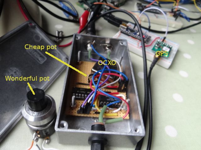
              The OCXO outputs a 10MHz signal, and for nefarious purposes I also need a 5MHz output. Easily done with a divider IC (if you wire it up the right way round). So far so good, but getting the best out of an OCXO requires it to be trimmed accurately to 10.000000 MHz. This is done by tweaking a pot, and turned out to be harder than expected, which I blamed on using an e-cheapo trimmer pot. Duncan Webster supplied a far better multi-turn pot, which is really too good to waste on this, and is a difficult tight fit in the box:

              dsc06672.jpg

              However, before fitting the new pot, I decided to measure the number of pulses output by the OCXO in 10 GPS seconds by counting them with an Arduino. 10MHz is too fast for an Arduino, but it happily counts at 5MHz. The result was unexpected: the highest count I got out of the OCXO divided down to 5MHz is 4999991211 (4.999991211MHz, which is apparently 8.78Hz below target.) The count is stable.

              Now I'm in a quandary: is the OCXO really wrong, or is there a problem with the Arduino and GPS? I trust the GPS, but maybe the Arduino's hardware counter consistently misses a few pulses, or I've programmed it wrong. How to prove it one way or another! There are a few things to try:

              • I can tell the GPS to output 4 second pulses,
              • I have a second OCXO. If it's also low, it suggests an Arduino problem, and up until today I've believed in it.
              • I can measure the OCXO with a picPET, to see if that makes a difference
              • I can compare the OCXO with the WWV time signal on 10MHz. Wasted a lot of time trying yesterday, and I'm not sure my equipment (a kiwiSDR) is good enough to detect an 8Hz difference, without involving a separate FFT analysis

              In other words, another simple problem has turned out to be a first class time-waster!

              Dave

              #634765
              Michael Gilligan
              Participant
                @michaelgilligan61133

                I suspect that Joe Noci might give us all a brief MasterClass sometime soon, Dave

                Meanwhile, it seems to me that the most accurate thing you have available is the GPS … and the ability to divide its output by integer values.

                MichaelG.

                #634776
                SillyOldDuffer
                Moderator
                  @sillyoldduffer

                  I'm looking forward to Joe's Masterclass!

                  Meanwhile, the results are in from the picPET, actually a pP06. By the by, in accordance with the rule that 'nothing is ever easy', there's probably a typo in the set up instructions, which say the device runs at 19200 baud. Mine runs at 9600!

                  Anyway, after converting the picPET's output from seconds to frequency, it also thinks the OCXO is low – 4999989.25, wrong by about 11Hz. Looks like I have a wonky OCXO

                  I think the 2Hz-ish difference between the Arduino and picPET is due to rounding error. picPET outputs seconds with 400nS granularity (to measure pendulum period), whilst the Arduino's been programmed to count the number of pulses received in 10 seconds (in hope of getting an accurate high-frequency measurement).

                  I'll try the other OCXO next.

                  Dave

                  #634799
                  duncan webster 1
                  Participant
                    @duncanwebster1

                    I don't mind asking the stupid question, why can't you adjust the pot to get it to 10 Mhz?

                    #634802
                    Michael Gilligan
                    Participant
                      @michaelgilligan61133
                      Posted by duncan webster on 24/02/2023 16:28:48:

                      I don't mind asking the stupid question, why can't you adjust the pot to get it to 10 Mhz?

                      .

                      Ah but … The question is: against what reference ?

                      MichaelG.

                      #634804
                      SillyOldDuffer
                      Moderator
                        @sillyoldduffer
                        Posted by duncan webster on 24/02/2023 16:28:48:

                        I don't mind asking the stupid question, why can't you adjust the pot to get it to 10 Mhz?

                        You missed a bit Duncan! The highest divide by two frequency I can get out of the OCXO, is 4.999991211MHz, which is 9.999982422 distinctly short of 10MHz.

                        The lowest frequency is 4.9999894, so the pot trims over a range of 1.8Hz on full travel, not enough to get the frequency up to 5 / 10MHz

                        Apparently, OCXO are shock sensitive, so this one may have been bumped in the past. Meanwhile, I can't find the other one to test it!

                        Dave

                        #634820
                        Joseph Noci 1
                        Participant
                          @josephnoci1

                          mm, trying hard not to get drawn too deep down this tunnel..I suffered it during my two GPSDO's development…

                          However..Any time to digital convertor – picpet, etc, must be fed with a ref frequency superior in accuracy/stability to the measurand – Michael said it – what is the reference you are using? Is it the GPS? If so , what frequency have you set its pps clock to? Not 10MHz I hope…

                          Michael also mentioned :

                          Meanwhile, it seems to me that the most accurate thing you have available is the GPS … and the ability to divide its output by integer values.

                          The divide by integer is not quite correct – to be clear, the only low jitter values the GPS 1PPS output can be programmed to are 1,2,4,8,16 and 24MHZ – ie, divide by 2's. 8 is an integer, and div by 8 gives 6MHz with bad jitter…etc.

                          HOWEVER, Bbe careful of the Monkey here…you can spend most of your spare time chasing a stable and accurate ref clock…while the stability and accuracy of you desktop pendulum is orders poorer than even a basic 1PPM TCXO.

                          Before said TCXO's characteristics are challenged and begin to contaminate the pendulum performance, you may find a year or more of pendulum development in the way…

                          A 1PPM 10MHz osc is quite adequate for substantial stability and frequency accuracy measurements. Use a 1ppm or 0.5ppm TCXO ( 10USD) , pack it in a styrofoam brick, stabilised PSU, settle for two or three days and you will be hard pressed to do better , and will not need to, till your pendulum is REALLY good…This will manifest in ADEV where the pendulum rivals the refclock, ie when ADEV gets down to around 10 minus 6 or so…

                          Using 1sec ref clocks from internet time servers, via the Pi, etc, timestamped and shuttled around – You have to be very good at it to not add subtle shifts and jitter to the result, which you will believe is good and will lead you astray. You have little means of verifying the quality of result.

                          Re the Freq of your OCXO Dave – I suggest it most unlikely that the 10Hz error is correct. An OCXO with 2Hz adjustment (0.2ppm) is generally reserved for fairly decent OCXO's – of which the frequency accuracy will generally be within the adjustment range after a specified aging life time, generally specced at 5 years, some even 10 years. Banging the OCXO will mess it up a bit, but it takes quite a bang, some 10's of G's..

                          It is all too easy to blame the indeterminable when the test setup is not quantified, qualified, and well understood.

                          Edited By Joseph Noci 1 on 24/02/2023 20:01:48

                          #634830
                          SillyOldDuffer
                          Moderator
                            @sillyoldduffer

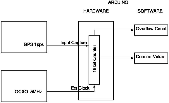
                            Should have provided a diagram! The set-up is intended to measure the frequency of a 10MHz OCXO, actually divided by 2 so the output is 5MHz.

                            ardcounter.jpg

                            Works like this:

                            A 5MHz square wave is fed from the OCXO into the external clock input of an Arduino counter timer. The counter is a hardware peripheral built into the microcontroller.

                            The GPS, outputting 1 second pulses is connected to the Counter's Input Capture Pin. Nothing happens until the GPS outputs a RISING edge, at which point the counter is incremented each time the OCXO pulses.

                            This continues until either:

                            • The counter overflows after 65535 pulses. When this happens, the counter resets to zero without stopping and sends an interrupt. The interrupt is detected by my program, which increments a variable. The variable counts overflows, and these occur every 0.0131072s at 5MHz.
                            • The GPS sends a second RISING edge. This copies the counter to a register and sends a different interrupt to my program. When received, the program knows a GPS second has passed, how many 5MHz pulses have been counted since the last overflow, and how many times the counter overflowed. So pulses received in 1 second = 65535 * overflows + last counter value

                            The reference is standard GPS seconds, and the OCXO's output is counted as an integer. The program actually counts 10 seconds worth of pulses, hence 4999991211, most of the time, sometimes varying by a single digit, rarely 2.

                            No pendulums involved, standard 1 second GPS pulses, and no floating point arithmetic.

                            Explaining it has given me an idea – watch this space!

                            Dave

                            #634836
                            SillyOldDuffer
                            Moderator
                              @sillyoldduffer

                              Posted by SillyOldDuffer on 24/02/2023 21:22:49:

                              Explaining it has given me an idea – watch this space!

                              Dave

                              How embarrassing is that. Looks like I made a silly mistake in the maths.

                              I said: pulses received in 1 second = 65535 * overflows + last counter value

                              Should be: pulses received in 1 second = 65536 * overflows + last counter value

                              Now the Arduino counts 49,999,907 pulses in 10 seconds from the OCXO, which is much closer – wrong by 0.93Hz

                              Dare I touch the trimmer?

                              Dave

                              #634837
                              Martin Kyte
                              Participant
                                @martinkyte99762

                                You beat me to it. Spot on correction.

                                Tweak the pot you know you want to.

                                regards Martin

                                #634840
                                Michael Gilligan
                                Participant
                                  @michaelgilligan61133
                                  Posted by Joseph Noci 1 on 24/02/2023 19:58:40:

                                  […]

                                  Michael also mentioned :

                                  Meanwhile, it seems to me that the most accurate thing you have available is the GPS … and the ability to divide its output by integer values.

                                  The divide by integer is not quite correct – to be clear, the only low jitter values the GPS 1PPS output can be programmed to are 1,2,4,8,16 and 24MHZ – ie, divide by 2's. 8 is an integer, and div by 8 gives 6MHz with bad jitter…etc.

                                  […]

                                  .

                                  Thank you, Joe … I happily stand corrected

                                  In fact I had an uneasy feeling just after I posted that comment,

                                  as if someone was whispering “are you sure about that?”

                                  MichaelG.

                                  #634846
                                  Joseph Noci 1
                                  Participant
                                    @josephnoci1
                                    Posted by SillyOldDuffer on 24/02/2023 22:12:48:

                                    Posted by SillyOldDuffer on 24/02/2023 21:22:49:

                                    Explaining it has given me an idea – watch this space!

                                    Dave

                                    How embarrassing is that. Looks like I made a silly mistake in the maths.

                                    I said: pulses received in 1 second = 65535 * overflows + last counter value

                                    Should be: pulses received in 1 second = 65536 * overflows + last counter value

                                    Now the Arduino counts 49,999,907 pulses in 10 seconds from the OCXO, which is much closer – wrong by 0.93Hz

                                    Dare I touch the trimmer?

                                    Dave

                                    I would'nt – 1 Hz error is within 0.1ppm for that OCXO – much better than your pendulum right now – MUCH better…

                                    Let the OCXO run with the picpet thingy and log data for 24hours – use timelab or whatever and do the ADEV and see what you get.

                                    #634862
                                    SillyOldDuffer
                                    Moderator
                                      @sillyoldduffer

                                      Disaster! I turned the pot slightly last night and the OCXO jumped to it's lowest frequency and stuck. I guess the wiper arm has come off the track. The pot is an un-shrouded crimped paxolin construction of the cheapest sort, and I shouldn't have used it in the first place.

                                      As the closest frequency to 5MHz was produced at full travel, I might get away with hard wiring the OCXO trim pin to 5V.

                                      The temperature behaviour of the OCXO is mildly interesting. Switched on from cold, the oven powers up and the case becomes hot to touch. The unit briefly outputs rubbish, then a frequency close to 10MHz appears. The datasheet says allow to settle for at least 30 minutes before trusting it.

                                      I have the OCXO mounted inside a die-cast metal box, which I expected to warm slightly as the air inside insulated the OCXO. In practice, the outer die-cast box gets distinctly warm during start-up, but cools down after the OCXO has been running for 15 minutes or so.

                                      I thought the oven would simply heat the crystal to operating temperature, when a simple thermostat would cut or apply power to the oven as necessary to keep the temperature stable. Like a domestic immersion heater. I guess the OCXO actually starts by heating beyond operating point for some time to thoroughly warm the crystal, case, and immediate surrounds before stabilising at operating temperature.

                                      Nothing about precision pendula is easy!

                                      Dave

                                      #634867
                                      duncan webster 1
                                      Participant
                                        @duncanwebster1

                                        Why does the exact frequency matter? As long as you know what it is, and it is stable, you can allow for it in the sums. The astronomical guys used to do this I think.

                                        I've got loads of those little 10k pots which look like they have a worm drive, if you want one shout. 

                                        Edited By duncan webster on 25/02/2023 10:25:10

                                        #634873
                                        John Haine
                                        Participant
                                          @johnhaine32865

                                          I have been thinking a bit further about how the T pulse must be generated in these GPS devices, reading the app note I linked to and looking at some comments on TimeNuts. This isn't necessarily the whole picture but my thoughts are…

                                          • They have a 48MHz master oscillator which is probably a TCXO. They do not lock this to the incoming satellite signal, it free runs. If it was locked it would be "disciplined" and we'd be home and dry already.
                                          • The time pulse is generated by a numerically controlled oscillator. This must have a phase accumulator that can accept a maximum count of 48 million. On each clock cycle a programmed value will be loaded into this and an output edge generated when the accumulator overflows. So for a 1pps signal the increment will be 1 and it will generate an edge every 48 million cycles, i.e. at 1pps (give or take the oscillator error). If the increment was 2 it would be 2Hz etc. Increment N, N Hz. This is standard direct digital synthesiser stuff.
                                          • If the increment isn't a factor of 48 million it will still generate the right mean frequency output but with jitter since the crystal edges and output edges will only align after several cycles around the 48 million count. The amount of jitter depends on the frequency – 10MHz seems to be specially bad.
                                          • Now there's another source of jitter since the 48MHz isn't locked to exact time. So the device has to keep track of the time difference and every so often make a time correction, probably by manipulating the number in the accumulator, so the next edge takes up the slack. But this can only be done to the accuracy of the 48MHz or about 21ns. It seems that there's a message available that announces such a correction and its amount.

                                          So the best approach seems to be to select a frequency that is divisible into 48 million (of which there are quite a few!) so that the inherent synthesiser jitter is low or zero, and accept that there will be an inherent 21ns jitter on what comes out to keep it frequency locked to "real" time. If this isn't acceptable then some form of additional PLL is recommended to clean up the signal – they suggest an Analog Devices chip but it seems to cost £££!

                                          #634890
                                          SillyOldDuffer
                                          Moderator
                                            @sillyoldduffer
                                            Posted by duncan webster on 25/02/2023 10:23:36:

                                            Why does the exact frequency matter? As long as you know what it is, and it is stable, you can allow for it in the sums. The astronomical guys used to do this I think.

                                            I've got loads of those little 10k pots which look like they have a worm drive, if you want one shout.

                                            Yes please to a little worm-drive trimmer – one of them will go inside the box with no bother, whereas fitting the nice pot requires major surgery.

                                            The exact frequency matters because the OCXO is intended to be a reference standard, against which lesser clocks will be measured. Makes life easier it's accurately on frequency.

                                            Michael raised the problem of how to know what the OCXO frequency actually is. Yes indeed! Done by comparing the OCXO with a more accurate time standard. The two methods I've attempted are:

                                            • By dividing the OCXO output by two, and then counting how many pulses it emits in 10 GPS seconds. This assumes that the divide by 2 is always correct, which it probably is; that the Arduino counter never misses a pulse or miscounts due to glitches; and that the PPS output of my GPS module is more accurate than the OCXO. I believe it is, but note John's comments above. There's a version of the GPS chip I'm using that's optimised for time measurement, the M8T, but I couldn't find one mounted on a breakout board. I don't have the technology or skills needed to solder sub-miniature devices.
                                            • Comparing the 10MHz signal directly with the WWV time signal broadcast on 10MHz shortwave. One way is to beat the two signals together to get an audible tone, and then tune for zero beat. Doesn't work well, partly because my human ear struggles to detect below about 30Hz, even if the communication receiver's audio system wasn't chopping off below about 300Hz, making it difficult to use an oscilloscope to detect zero beat. Not tried yet, but a better way seems to be to feed the audio beat into a FFT analyser, which shows very small frequency differences visually. A major problem with WWV is the signal fades in and out and is always weak. Although the frequency is rock solid, it's hard to use.

                                            All this is analogous to workshop, tool-room and calibration accuracy. To check a workshop micrometer, one needs a 10x better standard, which a tool-room typically works to. In turn, the tool-room works relative to calibration standards, which are 10x better again. And they're derived from even more precise metrology standards… Going up the hierarchy, achieving an appropriate level of accuracy gets exponentially harder. Not difficult I find to fashion metal within a thou, whilst getting tenths accuracy takes much more care, and considerable uncertainty about the results because they are hard to measure accurately and reliability.

                                            Some aspects of what I'm doing with my toy pendulum are taking me into the time equivalent of tool-room territory. I admit it's as much out of interest as necessity!

                                            Dave

                                            #635311
                                            Mason Green
                                            Participant
                                              @masongreen60104
                                              Posted by John Haine on 05/02/2023 10:16:43:

                                              To kick this off, since the subject of Harrison's clocks has come up, I thought that I'd post this link to a collection of 3 articles that I wrote a few years back, two in Horological Science News with my friend Andrew Millington, and one (summary) in Horological Journal. I put these together for SoD yesterday but they may be of more general interest.

                                              Excellent, thank you for sharing your papers. Looking forward to the read.

                                              Has this relatively recent paper on the grasshopper escapement already been discussed in this thread?

                                              Entropy of Timekeeping in Mechanical Clocks

                                              "To reduce the errors caused by random noise, one should aim for the largest practical pendulum energy. Moreover, as shown in [17], in systems with lower Q factor the effects of any disturbance die out faster, so that the pendulum returns to steady-state operation in a shorter time, producing smaller total timekeeping error (sum of period errors). The brilliance of grasshopper escapement lies in the fact that a pendulum with low Q factor and large amplitude is exactly the right choice to reach the local minimum ∂T /∂A, so that the clock becomes insensitive to both long-term and short-term disturbances."

                                              Harrison had it right from the beginning.

                                              Lecture based on the paper:

                                              **LINK**

                                              –MG

                                              #635317
                                              Michael Gilligan
                                              Participant
                                                @michaelgilligan61133

                                                Thanks for the links, Mason yes

                                                That paper was new to me … I will hopefully read it later today.

                                                MichaelG.

                                                #635322
                                                SillyOldDuffer
                                                Moderator
                                                  @sillyoldduffer
                                                  Posted by Mason Green on 28/02/2023 02:03:18:

                                                  Posted by John Haine on 05/02/2023 10:16:43:

                                                  To kick this off, since the subject of Harrison's clocks has come up, I thought that I'd post this link to a collection of 3 articles that I wrote a few years back, two in Horological Science News with my friend Andrew Millington, and one (summary) in Horological Journal. I put these together for SoD yesterday but they may be of more general interest.

                                                  Excellent, thank you for sharing your papers. Looking forward to the read.

                                                  Has this relatively recent paper on the grasshopper escapement already been discussed in this thread?

                                                  Entropy of Timekeeping in Mechanical Clocks

                                                  Thanks for sharing the paper, clever stuff, much food for thought in it. It contains a link to the test clock used, which is built of Lego!

                                                  And, our very own John Haine provided two of the references:

                                                  [14] J. Haine, A. Millington, Investigating the Harrison
                                                  Pendulum Oscillator, Horological Science Newsletter
                                                  NAWCC 3, 161, 2-18 (2016).
                                                  [15] J. Haine, A. Millington, Investigating the Harrison Pen-
                                                  dulum Oscillator – Part 2: Barometric Compensation
                                                  Methodology, Horological Science Newsletter NAWCC 4,
                                                  161, 2-24 (2016).

                                                  Dave

                                                  #635329
                                                  John Haine
                                                  Participant
                                                    @johnhaine32865

                                                    Other Lego grasshopper escapements in action, with a variety of other clock-related things, at

                                                    https://www.youtube.com/@horolophile/videos

                                                    **LINK**

                                                    Interesting that both the Shortt and Fedchenko pendulums have much higher Q and very small amplitude and are nevertheless significantly more stable. For a comparison (not showing Fedchenko) see page 72 of:

                                                    **LINK**

                                                    The Shortt at least is mechanically impulsed (though the mechanism is reset by an electromagnet)

                                                    #635431
                                                    Mason Green
                                                    Participant
                                                      @masongreen60104
                                                      Posted by John Haine on 28/02/2023 10:27:08:

                                                      Interesting that both the Shortt and Fedchenko pendulums have much higher Q and very small amplitude and are nevertheless significantly more stable. For a comparison (not showing Fedchenko) see page 72 of:

                                                      I'm sure the mechanical phase-locked loop, which provides negative feedback to the system, has a lot to do with it.

                                                      I find it extremely interesting that Ziemkiewicz's paper shows that the Harrison's pendulum period is accurately modeled by assuming the "random forces" acting on it follow a Maxwell-Boltzmann distribution. Thus the clock error behaves as a fractal, showing the system has long-term memory!

                                                      Essentially over a long period of time the pendulum is self-correcting despite the random forces acting on it.

                                                      –MG

                                                    Viewing 25 posts - 76 through 100 (of 502 total)
                                                    • Please log in to reply to this topic. Registering is free and easy using the links on the menu at the top of this page.

                                                    Advert

                                                    Latest Replies

                                                    Viewing 25 topics - 1 through 25 (of 25 total)
                                                    Viewing 25 topics - 1 through 25 (of 25 total)

                                                    View full reply list.

                                                    Advert

                                                    Newsletter Sign-up