Precision pendulum techniques

Advert

Precision pendulum techniques

Home Forums Clocks and Scientific Instruments Precision pendulum techniques

Viewing 25 posts - 51 through 75 (of 502 total)
  • Author
    Posts
  • #633291
    Clive Steer
    Participant
      @clivesteer55943

      I thought that this thread was started in order to discuss the techniques needed to achieve a precision pendulum.

      Unfortunately, like many of the threads, this one has moved on to discussing where one might obtain a 7/32 milling cutter.

      I think the reason the impulse pallet needs to be the shape is and how this shape contributes to pendulum precision would be more informative.

      CS

      Advert
      #633292
      Michael Gilligan
      Participant
        @michaelgilligan61133

        Being a simple old-fashioned soul, and the original being drawn in thirtyseconds, I had presumed the use of an 8x template and a pantograph machine.

        MichaelG.

        #633293
        Michael Gilligan
        Participant
          @michaelgilligan61133
          Posted by Clive Steer on 13/02/2023 16:54:55:

          I thought that this thread was started in order to discuss the techniques needed to achieve a precision pendulum.

          […]

          I think the reason the impulse pallet needs to be the shape is and how this shape contributes to pendulum precision would be more informative.

          .

          Matters fairly well-covered in the two books by FH-J

          MichaelG.

          .

          P.S. You mentioned, Clive, that you were going to the Frodsham workshop …

          Do you have any pearls of wisdom to share with those of us less fortunate ?

          Edited By Michael Gilligan on 13/02/2023 17:18:35

          #633302
          John Haine
          Participant
            @johnhaine32865

            From my reading of the book(s), though Shortt suggested the "raised cosine" design to FH-J after thinking it up whilst listening to Frank presenting at the IEE (in 1910?), it was described as only a theoretical idea. Actually there's no particular reason why a raised cosine should be better except that it starts and ends very gently and builds up in the middle then "fades away". But the actual shape hardly matters for a high Q pendulum. I'd decided to make my pallet by profiling anyway so needed some shape, and having read the book I saw it as an interesting challenge to adopt Shortt's.

            #633358
            Clive Steer
            Participant
              @clivesteer55943

              Michael

              I did indeed go to the Frodsham workshop and spoke to the guys there. What I found out was that Burgess B completion was a team effort which also included inputs from Jonathan Betts and Martin Burgess himself. Unfortunately, David, the guy who did much of the work is away at the moment taking care of his elderly parents but I do hope to speak to him soon. After Burgess B was completed David made a minimalist "clock" with a fused quartz pendulum rod, grasshopper escapement and mechanical remontoire driving the escape wheel. This was built to explore the accuracy of a pendulum operating at a high amplitude. After initial testing of the clock using a weight driven arrangement to power the remontoire they decided to use an electrically wound remontoire to power the mechanical remontoire ie have two cascaded remontoires. I designed the electronics to control the electrical winding.

              On installing the new winding system the clock would occasionally stop and naturally they blamed the "new" electronics. I retested its function but could find no reason for it being the cause of a stoppage. In the end I just needed to look in the right place more carefully and found the issue was caused by the mechanical remontoire jamming.

              Sadly the project is on hold at the moment but the intention is to fully instrument it to measure environmental conditions, pendulum timing with optical sensors and a laser range finder for monitoring pendulum amplitude.

              I'll post more info when I have it.

              CS

              #633367
              Michael Gilligan
              Participant
                @michaelgilligan61133

                Thanks for the notes, Clive yes

                MichaelG.

                .

                Philosophical thought for the day:

                An accurate pendulum is generally more useful if it keeps going.

                #633378
                Clive Steer
                Participant
                  @clivesteer55943

                  The final drive to the escape wheel was through a large wheel onto a trundle type pinion made up of two crossed out discs with 1mm trundle pins. On these were mounted 1mm bore x 3 mm OD ball races to act as a Harrison style anti friction wheel. There were gaps either side of the ball race and the discs which wasn't a problem providing the wheel ran true. However due to wear, handling or accident the wheel didn't run true and a engaging tooth would slip sideways off the race into the gap and jam. My solution was simply to use two races per pin to fill the gap between the discs. Swiss cheese effect in a bent tooth finding a race not exactly in the centre of a hunting tooth configuration.

                  CS

                  #633911
                  SillyOldDuffer
                  Moderator
                    @sillyoldduffer

                    This post is overflow from my experimental pendulum thread where Joe Noci recommended using a ublox GPS module as a high accuracy signal source. Many GPS modules, not all, provide a one pulse per second output that can be used to calibrate a pendulum. Many of the ublox range go a step further by allowing the user to set the pulse output to any period. This is very handy, for example I need an accurate 10MHz signal, and other frequencies.

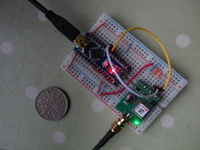
                    For hobby work it's convenient to avoid sub-miniature soldering by buying GPS module already mounted on a breakout board. Mine is a Uputronics uBLOX MAX-M8Q Breakout for Active Antennas – 5V from Pi-Hut, because I shall mainly use it with 5V Arduinos. The 3.3V version is better for microcomputers that run at that voltage. Level converters are cheap.  If the 5V version is bought, the EN pin should be jumpered to 5V.

                    dsc06669.jpg

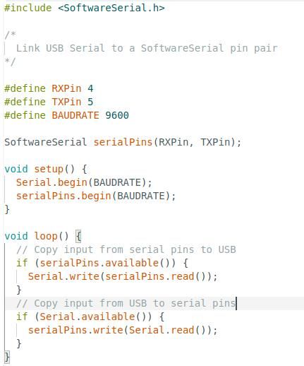
                    Photo shows the GPS module connected to an Arduino Nano programmed to convert TTL serial output to USB: a converter cable does the same job. The Arduino program is simple:

                    ardserial.jpg

                    When the Arduino is plugged into a computer it registers as a serial device that can be read by any suitable program.

                    Change frequency, I downloaded u-center 22.07 from ublox. Installed OK on my Windows 10 laptop but not my Windows 10 workstation. I understand the problem, MSCVR202.DLL is missing, but haven't managed to fix it yet.

                    u-center is intimidating! However, frequency is changed by selecting 'Configure', then 'CFG', then 'TP'. This opens a dialogue allowing frequency to be changed. It's a bit quirky: tick 'active', then change frequencyPeriod AND frequencyPeriodLock. Press the send button. It may be necessary to toggle the active tick box to get the change to take effect. Apologies if the configure instructions are misleading, I experimented briefly and may be doing it wrong!

                    Manuals:

                    M8 Receiver Description including Protocol Specification

                    MAX M8 Series

                    Will write a program to simplify frequency changing so watch this space.

                    Dave


                    Edited By SillyOldDuffer on 17/02/2023 17:53:32

                    #634051
                    John Haine
                    Participant
                      @johnhaine32865

                      Dave, is u-centre a "suitable program" or does one need to have a terminal program running too please?

                      Edited By John Haine on 18/02/2023 20:28:26

                      #634053
                      Joseph Noci 1
                      Participant
                        @josephnoci1

                        You only need U-Centerand a serial or usb to serial to the GPS, is all. If your GPS is one with Flash, you can write the setup to it and it will be sticky and come up like that on power up.

                        #634056
                        John Haine
                        Participant
                          @johnhaine32865

                          Thanks!

                          #634059
                          Joseph Noci 1
                          Participant
                            @josephnoci1

                            Select the correct port, and baudrate ( usually 90600) ( 2nd line from top. left of screen).

                            The select VIEW, then CONFIGURATION VIEW, the scroll down on the left to TP or TP2 to set up the Frequency on the pps pin. Then lower left of that screen, make sure the yellow lock is unlocked, and click on SEND…

                            #634069
                            SillyOldDuffer
                            Moderator
                              @sillyoldduffer

                              u-center is the easiest way of I've found so far. There's also ubxtool on Linux which works with the gpsd daemon.

                              NMEA output is in ASCII and can be read with a terminal emulator. However, UBX, used to send and read configuration data, is binary. It needs a program like u-center to encode and decode it, not a terminal emulator.

                              I'm writing a program to simply send change frequency commands and have hit a problem. It's that I can't get the UBX-CFG-TP5 specification on page 272 of the "u-blox 8 / u-blox M8 Receiver description including protocol specification" to exactly match the hex dump from u-center. I think the spec says rfGroupDelay is a 2 byte integer when it's actually a 4 byte integer. Or I'm reading it wrong! Any experience of this Joe?

                              When I get it right, sending the magic hex incantation:

                              B5 62 06 31 20 00 00 01 00 00 32 00 00 00 80 96 98 00 80 96 98 00 00 00 00 80 00 00 00 80 00 00 00 00 6F 00 00 00 55 7A

                              to the chip should set the M8Q to 10MHz with a 50% duty cycle. 10000000 is the little-endian sequence 0x00, 0x80, 0x96, 0x98

                              Dave

                              #634119
                              Joseph Noci 1
                              Participant
                                @josephnoci1

                                Sorry Dave – I have never needed to program the PPS output on the fly – always set it to a single value as per application needs. I have also for this only used GPS types with FLASH, so it was easier to just use Ucenter and program the flash so it remained fixed on power on.

                                #634134
                                John Haine
                                Participant
                                  @johnhaine32865

                                  I've now got my M8 running and linked to u-centre. I'm going to try manually setting my OCXO using the picPET to start with.

                                  #634158
                                  Joseph Noci 1
                                  Participant
                                    @josephnoci1

                                    Do you have a dual trace scope John? – A quicky is to set the GPS to 1MHz, trigger the scope on that, and feed the OCXO 10MHz into the other channel – adjust the OCXO so the trace stays put..

                                    #634220
                                    John Haine
                                    Participant
                                      @johnhaine32865

                                      Well I got the unit connected to the picPET and a bit of Pi code written to acquire some numbers, "measuring" the 1pps period. Good news, to 7 places of decimals it's 0.9999999s +/1 a bit. Bad news 1: hardly any perceptible change with the pot setting! Bad news 2: the GPS is very flaky, regularly losing lock. I get a decent position using "GPS Monitor" on my phone inside just next to the equipment, but I have the GPS antenna on the end of a piece of 3m cable on the windowsill / on top of the green wheely-bin outside the window. The antenna nominally has 30 dB gain, I think it's going back to Amazon!

                                      #634236
                                      SillyOldDuffer
                                      Moderator
                                        @sillyoldduffer
                                        Posted by John Haine on 19/02/2023 17:15:48:

                                        Well I got the unit connected to the picPET and a bit of Pi code written to acquire some numbers, "measuring" the 1pps period. Good news, to 7 places of decimals it's 0.9999999s +/1 a bit. Bad news 1: hardly any perceptible change with the pot setting! Bad news 2: the GPS is very flaky, regularly losing lock. I get a decent position using "GPS Monitor" on my phone inside just next to the equipment, but I have the GPS antenna on the end of a piece of 3m cable on the windowsill / on top of the green wheely-bin outside the window. The antenna nominally has 30 dB gain, I think it's going back to Amazon!

                                        I've found the M8Q works better than my Adafruit Ultimate GPS, probably because the M8Q picks up GLONASS (Russian) satellites as well as GPS(USA).

                                        Even with an active antenna the Adafruit is fussy about location. Inside the house and looking out a North facing window are both unsatisfactory. Looking out my south facing dining room it works with occasional drop-outs. West facing upstairs windowsill it seems to work 100%.

                                        I also had trouble with the pot setting and wish I'd bought a multi-turn one rather than using a cheapo trimmer. The trimmer turns in jumps and starts, and is pressure sensitive. I can get the 10MHz waveform stable by carefully turning it with an oscilloscope compensation screwdriver, but frequency slides as soon as I let go.

                                        My 40+ year old Racal 7-digit counter only measures in microseconds. It counts 1000000 OCXO pulses in 1 GPS second, but the last digit jitters a little.

                                        Haven't tried PET yet. The plan is to set the M8Q PPS to 0.25Hz (by setting period to 4000000uS), and see what ardPET makes of a 5MHz input. (I've wired my OCXO to a 7490 divide by 2 chip). I'll also try modifying ardPET to count more input pulses by extending the timing period to 'n' GPS pulses.

                                        Meanwhile I've nearly cracked how to change ublox TP frequency with a Python program. The bUblox TP5 spec isn't wrong as I suspected, I misread it! The mismatch was because message length is sent as a 16 bit integer, not 8 bit as I'd assumed.

                                        Code not quite working yet because I assumed duty cycle was sent as an integer, and it's not. 50.0% encodes to 0x80 (128), and 60% to 0x9a999999. I suspect the duty ratio is sent as a single precision float.

                                        Dave

                                        #634335
                                        SillyOldDuffer
                                        Moderator
                                          @sillyoldduffer

                                          I've completed a Python Program that sets the Ublox M8Q GPS time pulse to any frequency between 1 and 24000000. (24MHz is the upper limit of my GPS)

                                          Needs python3 and the struct and serial modules

                                          By default the program runs on Linux and expects the serial device to be on /dev/ttyUSB0 which is where the M8Q usually appears on my system. This may vary depending on the distribution and what else is plugged in to USB. Not tested, but the code should run on Windows where the serial device will appear in the COM1, 2, 3 series. The device can be edited at the top of the program.

                                          Code available on dropbox here.

                                          Dave

                                          #634515
                                          Michael Gilligan
                                          Participant
                                            @michaelgilligan61133

                                            Apologies if this has been linked already: **LINK**

                                            https://hgss.copernicus.org/articles/11/215/2020/hgss-11-215-2020.pdf

                                            Time and tide: pendulum clocks and gravity tides __ Duncan C. Agnew

                                            It’s interesting, recent, and includes a goodly list of references.

                                            MichaelG.

                                            #634516
                                            John Haine
                                            Participant
                                              @johnhaine32865

                                              Thanks for the code Dave, I'll give it a try when I get my antenna!

                                              #634551
                                              John Haine
                                              Participant
                                                @johnhaine32865

                                                Thanks to a posting on the Time Nuts list I found this u-blox application note:

                                                **LINK**

                                                Though written around the Lea 6 devices it is probably applicable to the M8 as well.

                                                #634552
                                                SillyOldDuffer
                                                Moderator
                                                  @sillyoldduffer

                                                  I came across William Scolnik's website, describing his impressive clock. Briefly:

                                                  Quartz Bob and Rod, Hall Effect detection, Hall Sensor position temperature compensated, Knife Edge suspension, electromagnetic impulse with precision power supply, electromechanical logic, and a vacuum tank:

                                                  Always fun to see the problems other run into! The vacuum tank is purpose made Pyrex with all the right seals, and it couldn't maintain a vacuum. Not because the tank or the seals were leaking: it was suffering from what the expert called a 'virtual leak', caused by the Pyrex and the rest of the clock degassing into a hard vacuum. To degas the whole, it was necessary to pump the vacuum for two days whilst heating the entire assemby to 120 degrees.

                                                  Doesn't bode well for my vacuum tank, which is a length of PVC drainpipe…

                                                  Dave

                                                  #634556
                                                  Martin Kyte
                                                  Participant
                                                    @martinkyte99762

                                                    But I guess you are not aiming for anything like a high vacuum which would require something a lot better than general mechanical roughing pumps. I don’t suppose you are planning to buy a turbo pump. Do you have any details of the vacuum system and their target pressure. I can’t actually see any connections to a pump in the picture and I’m assuming the system is not intended for continuous pumping. I suspect their initial problem was getting rid of the water. I’m not a vacuum engineer but we have built a number of high and ultra high vacuum systems in the Lab for me to have picked up a little. We certainly from the electronics end of things have to be very careful of any materials we choose to introduce including cable  insulation.

                                                    Regards Martin

                                                    Edited By Martin Kyte on 22/02/2023 09:47:04

                                                    Edited By Martin Kyte on 22/02/2023 09:48:11

                                                    #634557
                                                    Clive Steer
                                                    Participant
                                                      @clivesteer55943

                                                      That is certainly an impressive clock. However I'm surprised he's operating it at such a hard vacuum although this may have only been during degassing. Water vapour and other organic materials are a major issue hence the need to bake.

                                                      To get really hard vacuum you would need several pumping devices starting with a dry claw pump, backing a turbo pump with a cold trap using liquid nitrogen and an ion pump to get rid of the last few molecules. I don't know what the vacuum requirements are for the latest 3nm semi-conductors but I'm sure they will be expensive.

                                                      Many plastics are a no no in high vacuum because of outgassing and that includes PVC covered wiring.

                                                      You may be able to buy stock Pyrex tube from a scientific glassware manufacturer. There is one near me in Hastings that I visited where they had a lathe for making large bell jars and other vessels. An impressive manufacturing process to see.

                                                      CS

                                                    Viewing 25 posts - 51 through 75 (of 502 total)
                                                    • Please log in to reply to this topic. Registering is free and easy using the links on the menu at the top of this page.

                                                    Advert

                                                    Latest Replies

                                                    Viewing 25 topics - 1 through 25 (of 25 total)
                                                    Viewing 25 topics - 1 through 25 (of 25 total)

                                                    View full reply list.

                                                    Advert

                                                    Newsletter Sign-up