Precision pendulum techniques

Advert

Precision pendulum techniques

Home Forums Clocks and Scientific Instruments Precision pendulum techniques

Viewing 25 posts - 476 through 500 (of 502 total)
  • Author
    Posts
  • #657352
    S K
    Participant
      @sk20060
      Posted by SillyOldDuffer on 21/08/2023 14:47:38:

      Yes I looked for jitter by triggering the scope on both input and output. I couldn't detect any jitter with either arrangement except on the falling slope of the output when the comparator is rapidly triggered by a short input pulses, say 3uS wide input pulses every millisecond. A 1mS wide pulse repeating every 0.5s doesn't cause any jitter.

      I'm sure you know what you are doing, but just to be clear: Using two channels, you trigger on the first edge (the input), and observe the variation in time between that edge and the second (the output). You can put your scope on infinite persistence or in envelope mode to see the variation building up over many sweeps. If your scope won't calculate RMS of that variation (not too many do), you can get a crude estimate of the RMS by dividing the peak-to-peak jitter by 6 or so.

      Advert
      #657353
      S K
      Participant
        @sk20060

        LOL: Last night I had an extended dream in which I was preparing a 400 page Ph.D. dissertation on … pendulums!

        This is getting crazy!

        #657355
        S K
        Participant
          @sk20060

          Posted by Joseph Noci 1 on 21/08/2023 15:26:01:

          Jitter on the 5us propagation delay is not easy to measure – what do you reference too? Sometimes one has to trust the data sheet…Jitter measured on my pendulum? – you are joking, I trust….the design and electronics is very immature at this early stage, so its a matter of elimination and improvement as we go – chucking out all LM211/311 comparators – they take a fortnight to switch, and using LT1394 zero volt detector switches – really fast and stable, but thats how it goes, measurements to come 'much' later.

          The TDC – is a device that measures accurately ( to the accuracy of a reference crystal clock) the difference between a START and a STOP pulse ( down to 2ns or so resolution) – the start being my rather accurate 1Hz pulse train from my GPSDO, and the stop pulse being the pendulum seconds pulse from the comparator. That delta is used to determine how accurate and stable the pendulum is, and feeds the ADEV computation in TIMELAB.

          It's very easy if you are pulsing the opto's input yourself, as SOD was (see the above post). But it's hard or impractical if it's installed in a pendulum, as you note. And the data sheet doesn't discuss that parameter. On the other hand, for a pendulum as a whole, just calculate the RMS variation in the period.

          Yes, I know about TDC's. I designed an 8-channel, 16 hit per channel one with 0.5ns resolution in a former life. But my query was due to the rather short range of that device relative to the period of a pendulum, with a maximum of 8ms in mode 2. If the two clocks (reference and pendulum) are asynchronous to each other, as they normally would be, then the difference between the two would not be in range most of the time. That's why I was wondering what use it would be put to.

          Edited By S K on 21/08/2023 15:55:02

          #657358
          Joseph Noci 1
          Participant
            @josephnoci1

            Sorry Dave, hijacking your thread again…

            Not sure what you mean by 'not in range most of the time' – If the pendulum period is one sec, and my reference from the GPSDO is 1sec, all I do is get the edges close to each other, within some usec ( by delaying my 1Hz counters in the GPSDO by the required amount) and then the TDC gives the delta between the reference and pendulum time. If that remains constant the pendulum is at 1Hz. The period of the pendulum is not what we are measuring, but its difference to the reference 1Hz – the same way one would measure the performance of an oscillator against a reference for ADEV.

            I set the Reference counter delay to place my reference 1Hz edge within 500ns of the pendulum edge, and then let it run and use mode 2 of the TDC and it works just fine..

            #657359
            Joseph Noci 1
            Participant
              @josephnoci1
              Posted by S K on 21/08/2023 15:44:16:

              Posted by Joseph Noci 1 on 21/08/2023 15:26:01:

              Jitter on the 5us propagation delay is not easy to measure – what do you reference too?

              It's very easy if you are pulsing the opto's input yourself, as SOD was (see the above post). But it's hard or impractical if it's installed in a pendulum

              Edited By S K on 21/08/2023 15:55:02

              What do you mean by 'hard'?  – in fact one simply cannot – the only way to get the internal comparator to flip is by blocking the apertures. There is no way to pulse the opto – unless you mean pulsing the led, which defeats the object – it would then be very slow indeed, while led emission builds up to the level needed by the detector, which is not really the way to use these things..

              Edited By Joseph Noci 1 on 21/08/2023 16:54:30

              #657364
              S K
              Participant
                @sk20060

                The TDC won't be in range most of the time (nearly all of the time, actually) if the two are asynchronous. They would have to be synchronized to within 500 ns or 8 ms for the device to work, depending on the mode. But I see you plan to delay the 1PPS signal. I'm curious about how you have done that or plan to do it? Up to a second or two is a long time, and jitter in that delay would likely show up too when you are trying to measure to 35-55ps!

                And I meant "hard or impractical" as in "basically impossible" in that situation (though there's always some way!).

                #657368
                Joseph Noci 1
                Participant
                  @josephnoci1
                  Posted by S K on 21/08/2023 17:32:36:

                  . But I see you plan to delay the 1PPS signal. I'm curious about how you have done that or plan to do it? Up to a second or two is a long time, and jitter in that delay would likely show up too when you are trying to measure to 35-55ps!

                  The GPSDO 10MHz disciplined oscillator output is gated with a signal from a counter that divides said 10MHz down to a 0.5Hz pulse. The pendulum pulse , a rising edge every 2sec , enables that counter array.

                  So, on the first pendulum rising edge, that counter counts down 2sec, which then enables the gate above. That gate feeds another counter array which also generates a 0.5hz train. That train feeds the TDC START. The pendulum 0.5Hz 'train' feeds the TDC STOP. at this point, the two 0.5Hz trains are 'almost' coincident and within TDC mode 2

                  #657371
                  S K
                  Participant
                    @sk20060

                    Oh, I see, you have a GPS disciplined oscillator? Nice! Can you provide a link to it? Thank you.

                    #657376
                    Joseph Noci 1
                    Participant
                      @josephnoci1

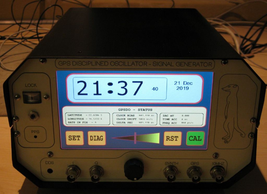
                      No link I fear, as both of mine are home made…One using an osc from a defunct HP Cesium Beam reference, the other a new, very good OCXO from Golledge in the UK.

                      Can only give you photos and circuits…but we must do so on another topic or email, etc…

                      Here's one..

                      front main page.jpg

                      #657379
                      S K
                      Participant
                        @sk20060

                        Very nice indeed! 🙂

                        #657693
                        John Haine
                        Participant
                          @johnhaine32865

                          I'm probably late to this party but had a sudden thought today. Though the measurements I did on the Sharp opto interrupter showed impressively low (sub micron) repeatability, I just realised that the emitter wavelength is 950nm, nearly 1 micron, so arguably whatever one does in the optical system will not I think improve the results.

                          #657696
                          S K
                          Participant
                            @sk20060

                            Great observation! Neat!

                            What does this position repeatability say about time resolution? After all, slowly incrementing a flag across the sensor only differs in velocity compared to swinging it across. I haven't calculated it, but doesn't one micrometer of travel correspond to a few ms in time, and isn't that around what most of us have been seeing?

                            #659684
                            S K
                            Participant
                              @sk20060

                              Thinking about John's observation: I find it improbable, but not impossible, that the 3-5us time resolution both John and I have seen is tied to the wavelength of light. That is, reaching the fundamental limits of physics (e.g. uncertainty principles) without any special effort, vs. hitting other more mundane limits such as electronic noise and ordinary measurement issues, would have come far too easily to be likely. But I declare that it's John's responsibility to analyze this further! 😉

                              Also, my new pendulum has achieved perpetual motion. It's never stopped oscillating, albeit with a small but easily noticed amplitude. That's not very good news, actually, as it speaks to a pronounced negative impact of the environment on a non-enclosed pendulum.

                              Edited By S K on 09/09/2023 16:21:48

                              #659698
                              SillyOldDuffer
                              Moderator
                                @sillyoldduffer
                                Posted by S K on 09/09/2023 16:17:06:

                                Thinking about John's observation: I find it improbable, but not impossible, that the 3-5us time resolution both John and I have seen is tied to the wavelength of light. That is, reaching the fundamental limits of physics (e.g. uncertainty principles) without any special effort, vs. hitting other more mundane limits such as electronic noise and ordinary measurement issues, would have come far too easily to be likely. But I declare that it's John's responsibility to analyze this further! 😉

                                Also, my new pendulum has achieved perpetual motion. It's never stopped oscillating, albeit with a small but easily noticed amplitude. That's not very good news, actually, as it speaks to a pronounced negative impact of the environment on a non-enclosed pendulum.

                                Too hot hot and tired to think clearly about wavelengths, but a period of 5uS is very much in the electromagnetic slow lane – 200kHz. 5nS is still fairly pedestrian – 200MHz. 5 picoseconds is more like it – 200GHz. Visible light is about 400THz

                                Really interesting question though – what limits the reliability of an IR beam break? Hmmm…

                                Dave

                                #659700
                                Martin Kyte
                                Participant
                                  @martinkyte99762

                                  I think you should set your opto sensor up in the lathe or mill with the same electronics and test out its positional accuracy. I suspect it’s not going to be great.

                                  regards Martin

                                  #659704
                                  John Haine
                                  Participant
                                    @johnhaine32865

                                    I have done this and posted the results here somewhere.

                                    #659705
                                    Martin Kyte
                                    Participant
                                      @martinkyte99762

                                      I had a feeling someone had John.
                                      regards Martin

                                      #659706
                                      S K
                                      Participant
                                        @sk20060

                                        If the position error of a sensor is 1um, and a pendulum is moving at say 1cm/s at the sensor, then there's an uncertainty of 1us in the sensor's timing – a reasonable number (but put in proper speed values).

                                        So, if the wavelength of light dictates the position uncertainty, then it also dictates the time uncertainty? If so, we must break out the ultraviolet laser or better yet an electron beam immediately! Hey, you are putting your pendulum in a vacuum already, after all! 😄

                                        #659708
                                        John Haine
                                        Participant
                                          @johnhaine32865

                                          This is my previous thread on the opto precision issue.

                                          **LINK**

                                          I wrote a longer article for HSN which I could share if of interest.

                                          #659712
                                          Joseph Noci 1
                                          Participant
                                            @josephnoci1
                                            Posted by John Haine on 09/09/2023 23:08:38:

                                            This is my previous thread on the opto precision issue.

                                            **LINK**

                                            I wrote a longer article for HSN which I could share if of interest.

                                            Please do.

                                            #659718
                                            John Haine
                                            Participant
                                              @johnhaine32865

                                              Just emailed to you, Joe.

                                              #659751
                                              S K
                                              Participant
                                                @sk20060

                                                Well, if the S.D. was found to be 0.15um, then there should be plenty of room for improvements in timing resolution.

                                                I still think that using a brighter light source (e.g. a laser) in conjunction with a fine slit should improve the timing as well as reducing the effect of stray light. I also bought a few of the optos that Joseph is using, but – warning – it seems I broke the first one I tried (they may be particularly sensitive to ESD, which the data sheet even prominently highlights in red letters). One day I'll get back to these investigations.

                                                Also, I've mostly been placing the opto at the end of the swing rather than at BDC. This way, I conveniently get a measure of the period directly, as opposed to half of the period (and annoyingly-different measures for the left vs. right swings). I've believed that this is not optimal, though, since the pendulum is moving slowest at its apex vs. fastest at BDC. It's probably indeed not optimal, but by John's measurement, it may not be that bad after all.

                                                #659754
                                                SillyOldDuffer
                                                Moderator
                                                  @sillyoldduffer

                                                  Posted by S K on 09/09/2023 16:17:06:

                                                  …That's not very good news, actually, as it speaks to a pronounced negative impact of the environment on a non-enclosed pendulum.

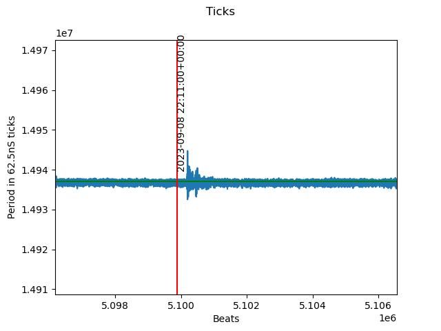
                                                  Isolating a pendulum from the environment is difficult. This graph is from my clock's log just after the severe earthquake in Morocco at 2023-09-08 22:11Z. The epicentre is about 2400km from me. Might be a coincidence, but I think it caused my house to wobble.

                                                  moroccoeq.jpeg

                                                  Dave

                                                  #659765
                                                  S K
                                                  Participant
                                                    @sk20060

                                                    Yes, that's quite likely due to that very serious and tragic earthquake.

                                                    If someone else here has similarly-good reference timing, you might even triangulate it.

                                                    #659785
                                                    Joseph Noci 1
                                                    Participant
                                                      @josephnoci1
                                                      Posted by S K on 10/09/2023 16:24:50:

                                                      Also, I've mostly been placing the opto at the end of the swing rather than at BDC. This way, I conveniently get a measure of the period directly, as opposed to half of the period (and annoyingly-different measures for the left vs. right swings). I've believed that this is not optimal, though, since the pendulum is moving slowest at its apex vs. fastest at BDC. It's probably indeed not optimal, but by John's measurement, it may not be that bad after all.


                                                      If you place the opto at BDC and clock a D type flip-flop (SN7474 etc) with the Opto's output you get a single rising edge per period swing. You eliminate the right-left-right deltas and get a true period measurement at each rising edge.

                                                      Connect not-Q to the D input and the Opto output to the clock input – use Q or not-Q as required by your measurement system


                                                      Edited By Joseph Noci 1 on 10/09/2023 18:55:10

                                                    Viewing 25 posts - 476 through 500 (of 502 total)
                                                    • Please log in to reply to this topic. Registering is free and easy using the links on the menu at the top of this page.

                                                    Advert

                                                    Latest Replies

                                                    Viewing 25 topics - 1 through 25 (of 25 total)
                                                    Viewing 25 topics - 1 through 25 (of 25 total)

                                                    View full reply list.

                                                    Advert

                                                    Newsletter Sign-up