Precision pendulum techniques

Advert

Precision pendulum techniques

Home Forums Clocks and Scientific Instruments Precision pendulum techniques

Viewing 25 posts - 26 through 50 (of 502 total)
  • Author
    Posts
  • #633053
    SillyOldDuffer
    Moderator
      @sillyoldduffer

      Posted by Tony Jeffree on 11/02/2023 11:57:31:

      My own rather amateurish messing around with a "free" pendulum that is electromagnetically impulsed under the control of a single board computer has led me to start thinking about a third possible approach which takes advantage of the processing power and electronic sensors that could be applied to the problem – measure the environmental factors that could affect the pendulum (temperature, pressure, humidity,…), feed those measurements into the SBC, and use its processing power to determine how much impulse to give to the pendulum in order to correct for the environmental effects. Even for the lowly BBC Micro Bit that I am using has add-on boards that will measure temperature, pressure, and humidity. Obviously the calculation is probably going to be non-trivial, and the details specific to a particular pendulum, but in principle…?

      …or are you all way ahead of me…?


      Similar to what I'm doing in the 'Experimental Pendulum' thread. My method:

      1. Build attempts a high Q pendulum without mechanical temperature or barometric compensation, that isn't designed to beat at a particular frequency. The bob is impulsed by an electromagnet, triggered by the bob breaking an infra-red beam, so there's nothing mechanical apart from my bad design and workmanship to spoil the pendulum. Not tried yet, but the pendulum is designed to run in a vacuum.
      2. Logs temperature, air pressure and humidity on every beat, also measuring period at high resolution for external statistical analysis.
      3. The statistical analysis quantifies the relationship between temperature, pressure, and humidity (if any). My clock isn't noticeably effected by humidity, so that's been dropped. The relationship between period, temperature and air pressure is quantified numerically by doing a 'Multivariable Regression', on the log.
      4. The regression results are loaded into the clock, where the microcontroller uses them to turn mechanical ticks into microsecond accurate 'should be values'. When time-keeping independently, the actual pendulum period isn't measured. Instead the tick event causes the microcontroller to calculate the 'correct' period from temperature and pressure, and it counts that rather than actual pendulum time. Very different from other clocks I believe!

      The log looks like this, millibars, humidity, and temperature in bold, actual period and corrected period in italics:

      13277507 0.4059 0.3600 36 1024.02 73.72 13.55 823472 1676117346 766006 1676118087 862746
      13279885 0.4059 0.3600 36 1024.02 73.72 13.55 823472 1676117347 589478 1676118088 688123

      Note that the microcontroller corrects both actual tick periods into the same value in microseconds based on temperature and pressure. The smoothing is aggressive, and may be cheating!

      The maths is easy enough, when you know how, because someone else did all the hard work! I'm using python with numpy and sklearn, both modules built by experts! Numpy is designed to make working with numeric arrays easy, whilst sklearn is a machine learning module that includes multi-variable regression. The two are compatible.

      Mult-vartiable regression may be complicated behind the scenes but the Python code needed to use it as a tool is simple:

      X = np.column_stack((pressures, temps)) # Combine pressure and temperature arrays
      regr = linear_model.LinearRegression() # Create an object that does regression sums
      regr.fit(X, ticks) # Get relationship between ticks( aka period), temperature and pressure

      intercept = regr.intercept_ # The answer is in three parts
      pressureCoef = regr.coef_[0]
      tempCoef = regr.coef_[1]

      Regression results loaded into the clock, the microcontroller uses the intercept, pressure and temperature coefficients to do a simple sum:

       
      void update( float temp, float pressure ) {
      float compPerioduS;
      if (compensate) {
      compPerioduS = (intercept + pressureCoef*pressure + tempCoef*temp);
      compPerioduS += cDrift;
      perioduS = round((compPerioduS/xtal)*1e6);
      }
      timePair.adduS(perioduS);
      }
      </code>

      Written in C because I'm using an Arduino, but nothing other languages couldn't do just as well.

      Example values:

      #define INTERCEPT 13112795.02168
      #define TCOEF 52.67560
      #define PCOEF 59.51222

      What I hadn't thought of doing is computing the impulse power as necessary to adjust Amplitude - an idea I shall certainly steal!

      smiley

      Thanks,

      Dave


      Edited By SillyOldDuffer on 11/02/2023 15:16:06

      Advert
      #633057
      Tony Jeffree
      Participant
        @tonyjeffree56510

        Interesting stuff Dave, thanks – there's plenty there for me to steal too!

        Cheers,

        Tony

        #633091
        S K
        Participant
          @sk20060
          Posted by Martin Kyte on 10/02/2023 22:12:34:

          I would consider the action of a roller falling under gravity for a fixed distance down a slope to be a more precise and constant impulse than an electromagnetic pulse even with fairly sophisticated electronics.

          This is something I have a hard time believing. Sure, in the days of "Electric Clocks" (no copyright page shown, but I'm guessing it was from the '40's), that was no-doubt true. Maintaining fine regulation of voltages and currents and impulse durations was very difficult back then, which would lead to horrible long-term performance. In addition, I think light detection with selenium elements was known back then, but that too would likely have been too slow and inaccurate for good timing.

          But do you believe that's somehow always going to be the case, even with modern electronics? If so, what specific issues do you think remain potentially worse about electronic measurement and impulsing than mechanical?

          I have barely any experience with clocks, but a fair amount of experience with electronics. My opinion would be that if the very best (electro-) mechanical clocks of old are still better than amateur attempts of today, that was likely due to the extraordinary skills of the best practitioners of the day, not the inherent superiority of mechanical impulsing.

          Edited By S K on 12/02/2023 01:20:27

          #633103
          SillyOldDuffer
          Moderator
            @sillyoldduffer
            Posted by S K on 12/02/2023 01:16:01:

            Posted by Martin Kyte on 10/02/2023 22:12:34:

            I would consider the action of a roller falling under gravity for a fixed distance down a slope to be a more precise and constant impulse than an electromagnetic pulse even with fairly sophisticated electronics.

            This is something I have a hard time believing. …

            But do you believe that's somehow always going to be the case, even with modern electronics? If so, what specific issues do you think remain potentially worse about electronic measurement and impulsing than mechanical?

            Different technologies usually come with a different list of virtues and vices. I don't see this as a straight competition, rather an opportunity for the designer to mix and match for best effect. For example, firearm design calls for materials expertise, mechanical engineering and energetic chemistry. The motor on my lathe calls for materials expertise, mechanical engineering, and electrical engineering. A lathe could be driven by an IC engine, but there are a long list of disadvantages.

            An advantage of impulsing with a falling weight is the force delivered can be determined very accurately. My experimental clock uses an electronic timer to deliver an ultra-accurate timed pulse to an electromagnet that then attracts the bob. Although the pulse is super-accurate, the resulting force applied to the bob is hard to guarantee, for example:

            1. The voltage applied to the electromagnet's coil may sag under load, causing the magnetic field to vary
            2. The coil's impedance effects the shape of the pulse, causing the field to vary
            3. The strength of the magnetic field weakens rapidly with distance, so the force applied to the pendulum depends on timing
            4. In my clock the bob is made of mild-steel, which is likely to become slowly magnetised itself by impulses. I think the change will alter when each impulse reaches the bob, causing a drift. I don't know how big the change will be, or how long it will take to appear.

            In practice, I dodge the first three by adjusting for best results, but I don't know how much force each super accurate pulse applies to the bob. Thus I can't give any sensible advice on how to wind an electromagnet from first principles, and the set-up doesn't provide much insight into the actual force applied to the pendulum. All I can do at the moment is give the part number of the 5V relay I cannibalised, describe it's physical position, state the pulse length, and graph various effects on period and overall time-keeping.

            In contrast, a dropped weight is less accurate in terms of 'when' the impulse force is applied, but much more predictable and measurable in terms of effect. Both are important if the aim is to explain why things work and why they fail so that the next design will be an improvement. My ideal system would be accurately predictable in terms of time and force, but I'm nowhere near achieving that! Hence much fumbling in the dark!

            Dave

            #633106
            Martin Kyte
            Participant
              @martinkyte99762

              My comments regarding falling mass impulsing was really just a gut reaction and you would have to look at the data to say for certain. Mass impulsing will be affected by changing gravity from tidal effects but they are small and predictable. Again a gut feeling but I would think it would be easier to do without introducing a wobble to the pendulum especially if the electromagnetic impulse was at the bottom of the bob.
              Im also twitchy about having a magnet on the bob with the system sitting in a varying magnetic field. The earth field varies and there are other sources of magnetic disturbance potentially on a more local level. Quite how much this would effect things I have no idea.

              Part of it is taste. I like mechanical solutions.

              For an electronically compensated clock I’m not sure it matters much anyway as the feedback from the amplitude input will compensate for any variation in impulse.

              regards Martin

              #633120
              John Haine
              Participant
                @johnhaine32865

                For my first clock I decided to use a gravity escapement based on the Synchronome for the reasons that Martin suggested. In fact I used an old 'Nome as a basis though the only parts retained are the cast frame and the gravity arm, and the dial mech (it came without a pendulum). The arm is lifted by a small stepper driving a snail cam, the pendulum sensed by an opto, and all controlled by an Arduino – hence "Arduinome". I used the stepper for the arm because it can be much better controlled, and the pallet design is based on the raised-cosine shape that Shortt proposed. In principle you can set up the clock so that the gravity roller is just half-way down the cam when the pendulum is stationary so the impulse should be exactly symmetric and centred. In practice that does not give an actual central impulse and looking at detailed timing measurements there is a distinct phase step on each impulse. Correcting this needs a real-time measurement of the time shift which is hard to do though I did kluge the control software to do it. Whether the adjustment survived the clock being moved from workshop to kitchen I don't know!

                I also found that I had to be very careful about setting the pallet exactly in the plane of swing to avoid imparting a twisting motion to the pendulum. The rod is carbon fibre and so very light, and the impulse also imparts a distinct "wobble" to the rod because the CoP is virtually at the bob CoG. So though in principle I think mechanical impulsing could be better (and in fact can be as in Clock B), I don't think it's any easier to set up than electromagnetic.

                Of course the Fedchenko clock shows that EM impulsing can be very precise and that has no amplitude control, instead a special spring design that corrects for circular deviation.

                #633121
                Tony Jeffree
                Participant
                  @tonyjeffree56510
                  Posted by Martin Kyte on 12/02/2023 09:40:55:

                  Im also twitchy about having a magnet on the bob with the system sitting in a varying magnetic field. The earth field varies and there are other sources of magnetic disturbance potentially on a more local level. Quite how much this would effect things I have no idea.

                  regards Martin

                  There's no need to have a magnet on the bob – mine has a soft iron armature attached which the electromagnet attracts. I do use a very small magnet for the Hall effect sensors though – but as others have done, optical sensors could be used.

                  #633154
                  Martin Kyte
                  Participant
                    @martinkyte99762
                    Posted by John Haine on 12/02/2023 11:39:06:

                    I also found that I had to be very careful about setting the pallet exactly in the plane of swing to avoid imparting a twisting motion

                    I thought that the pallet was meant to be the segment of a circular cone with the proper profile if that makes any sense. Think of a sectioned bell perhaps. That way the slope is always radial to the rod so provided the roller is square to the swing there should not be any twist. I made mine like that but as it’s not finished I cannot comment on the outcome.

                    regards Martin

                    #633155
                    Martin Kyte
                    Participant
                      @martinkyte99762
                      Posted by Tony Jeffree on 12/02/2023 11:46:29:

                      Posted by Martin Kyte on 12/02/2023 09:40:55:

                      Im also twitchy about having a magnet on the bob with the system sitting in a varying magnetic field. The earth field varies and there are other sources of magnetic disturbance potentially on a more local level. Quite how much this would effect things I have no idea.

                      regards Martin

                      There's no need to have a magnet on the bob – mine has a soft iron armature attached which the electromagnet attracts. I do use a very small magnet for the Hall effect sensors though – but as others have done, optical sensors could be used.

                      Fair comment.

                      #633160
                      John Haine
                      Participant
                        @johnhaine32865

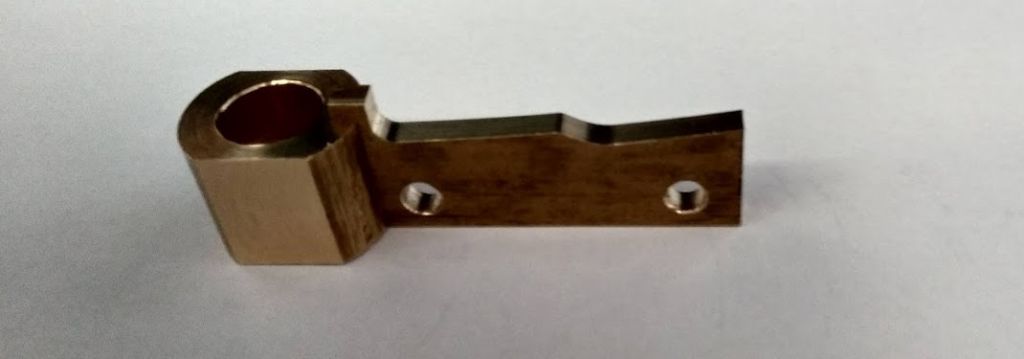
                        pallet_2.jpg

                        My pallet is just 1/8" wide so not much opportunity to shape it.

                        #633163
                        Martin Kyte
                        Participant
                          @martinkyte99762

                          That would explain it John. Mine looks nothing like that.

                          regards Martin

                          #633169
                          Michael Gilligan
                          Participant
                            @michaelgilligan61133
                            Posted by Martin Kyte on 12/02/2023 18:02:57:

                            That would explain it John. Mine looks nothing like that.


                            .

                            Putting my head briefly above the parapet … may I refer to my post on 01-Feb, here at 17:18:26  **LINK**

                            https://www.model-engineer.co.uk/forums/postings.asp?th=184659&p=2

                            MichaelG.
                            [ exits before the flak starts flying ]

                            Edited By Michael Gilligan on 12/02/2023 18:53:45

                            #633173
                            Martin Kyte
                            Participant
                              @martinkyte99762

                              Thats what mine looks like. Made with a form tool with the pallet on an arbor in the chuck to generate the circular arc. That way if the pallet is slightly skew it doesn't matter.

                              regards Martin

                              #633195
                              John Haine
                              Participant
                                @johnhaine32865

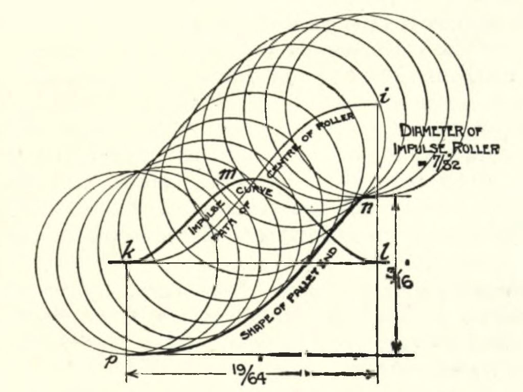
                                Well, strictly the pallet face isn't circular! Mine is CNC profile milled, such that a follower roller of the right diameter follows a path that gives a raised-cosine force, just like the red curve in the picture you posted Michael. Probably a circular arc isn't far off though.

                                #633200
                                duncan webster 1
                                Participant
                                  @duncanwebster1

                                  Am I correct in thinking that Michael's red curve doesn't allow for the roller diameter? The scan appears more sharply curved at the top

                                  #633203
                                  Clive Steer
                                  Participant
                                    @clivesteer55943

                                    As I understand it only the length of a pendulum rod and the restoring force exerted by gravity determine the frequency of oscillation of a pendulum.

                                    Variations in rod length due to temperature can be reduced by using a rod of Invar, fused quartz or other slow thermal expansion materials. Variations in the restoring force acting on the bob mass caused by air pressure/density may be offset by a barometric compensator or operating the pendulum in a controlled atmosphere.

                                    Both of these are both simple and effective to implement.

                                    However for a simple pendulum the issue of circular error and the need to stabilise amplitude is a difficult issue to solve if the history of clock development so far and the discussions here are anything to go by. Numerous escapements, drive train improvements and increasing levels of pendulum detachment have been devised to help produce a stable amplitude.

                                    Fedchenko side stepped the problem by using a suspension design that eliminated or at least substantially reduced circular error and therefore reduced the need to stabilise amplitude.

                                    There have been several methods devised to reduce the effects of circular error such as the spring used on the Bulle electric clock that compensated for the reduction of battery voltage over time and reduced impulse energy.

                                    Although this method doesn't reduce circular error to the extent the Fedchenko's design does it will go some way to reduce the need for highly accurate impulsing. Also on an electrically impulsed pendulum one can easily change the impulse energy to see if such a method makes the pendulum more isochronous.

                                    CS

                                    #633204
                                    Michael Gilligan
                                    Participant
                                      @michaelgilligan61133
                                      Posted by duncan webster on 13/02/2023 00:09:38:

                                      Am I correct in thinking that Michael's red curve doesn't allow for the roller diameter? The scan appears more sharply curved at the top

                                      .

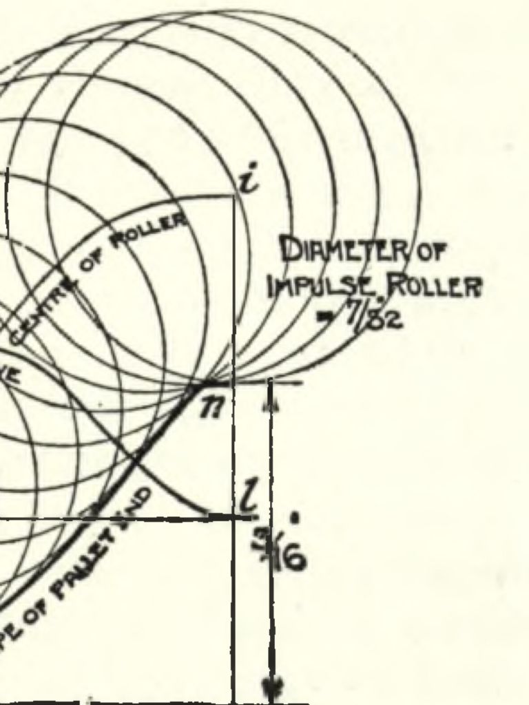
                                      Michael’s red curve is the ‘Path of Centre of Roller’ … not the ’Shape of Pallet End’

                                      … We were ‘reverse engineering’ the diagram, to work out how to mill the shape using a cutter having the same 7/32” diameter as the roller.

                                      MichaelG.

                                      beb24339-17dc-442a-9ae2-8667840bb0c7.jpeg

                                      .

                                      MichaelG.

                                      .

                                      Edit: [for the avoidance of doubt] __ the ‘Diameter of Impulse Roller’ is shown as 7/32”

                                      .40301f53-7bd8-4713-a9fa-b273e994a9e4.jpeg


                                      Edited By Michael Gilligan on 13/02/2023 03:11:28

                                      #633205
                                      Michael Gilligan
                                      Participant
                                        @michaelgilligan61133

                                        This is probably the best video i have seen of the Synchronome Switch in action:

                                        .

                                        .
                                        Signing-out and trying to get back to sleep now.
                                        MichaelG.

                                        #633211
                                        John Haine
                                        Participant
                                          @johnhaine32865

                                          Nice video! Brian Mumford used to have a time lapse one showing it in slow motion on his website but it has gone.

                                          The problem of profiling the pallet is that 7/32 cutters aren't a standard size so a path has to be worked out to use a smaller one.

                                          #633214
                                          Michael Gilligan
                                          Participant
                                            @michaelgilligan61133
                                            Posted by John Haine on 13/02/2023 08:28:58:

                                            […]

                                            The problem of profiling the pallet is that 7/32 cutters aren't a standard size so a path has to be worked out to use a smaller one.

                                            .

                                            Could be worth grabbing one of these: **LINK**

                                            https://www.chronos.ltd.uk/product/hss-endmill-7-32-diameter/

                                            Edit: or plain-shank carbide from Zoro :

                                            https://www.zoro.co.uk/shop/cutting-tools/carbide-end-mills-regular-series/7-32inch-4fl-standard-carbide-end-mill/p/ZT1151543X

                                            .

                                            …or re-scaling the components slightly, and using 5.5mm 

                                            MichaelG.

                                            Edited By Michael Gilligan on 13/02/2023 09:03:12

                                            #633225
                                            duncan webster 1
                                            Participant
                                              @duncanwebster1
                                              Posted by Michael Gilligan on 13/02/2023 02:58:34:

                                              Posted by duncan webster on 13/02/2023 00:09:38:

                                              Am I correct in thinking that Michael's red curve doesn't allow for the roller diameter? The scan appears more sharply curved at the top

                                              .

                                              Michael’s red curve is the ‘Path of Centre of Roller’ … not the ’Shape of Pallet End’

                                              … We were ‘reverse engineering’ the diagram, to work out how to mill the shape using a cutter having the same 7/32” diameter as the roller.

                                              MichaelG.

                                              .

                                              MichaelG.

                                              .

                                              Edit: [for the avoidance of doubt] __ the ‘Diameter of Impulse Roller’ is shown as 7/32”

                                              .

                                              Edited By Michael Gilligan on 13/02/2023 03:11:28

                                              That makes sense

                                              #633230
                                              John Haine
                                              Participant
                                                @johnhaine32865

                                                I must admit I didn't bother to look if a 7/32 mill was available, as I preferred to use a size I already had (4mm IIRC). I could have changed the roller diameter but I was using the original gravity arm and roller.

                                                #633245
                                                Martin Kyte
                                                Participant
                                                  @martinkyte99762
                                                  Posted by John Haine on 12/02/2023 22:31:37:

                                                  Well, strictly the pallet face isn't circular! Mine is CNC profile milled, such that a follower roller of the right diameter follows a path that gives a raised-cosine force, just like the red curve in the picture you posted Michael. Probably a circular arc isn't far off though.

                                                  The circular arc I was referring to was the arc accross the pallet face. Probably my bad description. If the pallet is CNC turned rather than milled you get a solid of rotation so that any inaccuracy in the angle its fixed at still presents a radial slope of your choice to the roller which has to lie in the plane of oscillation. At least that what I read.

                                                  regards Martin

                                                  #633254
                                                  duncan webster 1
                                                  Participant
                                                    @duncanwebster1

                                                    Would a barrel shaped roller have the same effect, but easier to make?

                                                    Edited By duncan webster on 13/02/2023 12:31:34

                                                    #633259
                                                    Martin Kyte
                                                    Participant
                                                      @martinkyte99762

                                                      I suppose a barrel shaped roller would still have to have the max diameter in the plane of the swing. It may well be easier to adjust which could be a major benefit.
                                                      For those requiring the raised cosine shape I suppose the other option is to CNC a form tool with the correct profile and use that to turn the ramp if you don’t have access to a CNC lathe.

                                                      regards Martin

                                                    Viewing 25 posts - 26 through 50 (of 502 total)
                                                    • Please log in to reply to this topic. Registering is free and easy using the links on the menu at the top of this page.

                                                    Advert

                                                    Latest Replies

                                                    Viewing 25 topics - 1 through 25 (of 25 total)
                                                    Viewing 25 topics - 1 through 25 (of 25 total)

                                                    View full reply list.

                                                    Advert

                                                    Newsletter Sign-up