Precision pendulum techniques

Advert

Precision pendulum techniques

Home Forums Clocks and Scientific Instruments Precision pendulum techniques

Viewing 25 posts - 451 through 475 (of 502 total)
  • Author
    Posts
  • #656686
    John Haine
    Participant
      @johnhaine32865

      Dave, perhaps time to start taking some ADev plots to get a feel for what sort of noise you have?

      Michael said:

      "Therefore … Stray light problems might be considerably reduced by inserting a suitable narrow-band-pass filter in the beam path."

      This I have done by inserting a strip of 2mm filter material (made for IR videoing to put in front of a light source) in front of the detector side of the sensor. Visually it's dead black but seems to have zero effect on the sensitivity of the Sharp but does get rid of the non-IR content of ambient illumination. Still a problem with sunlight that has a lot of IR which is why I plan to put some 3M solar film over the glass door of the case.

      Advert
      #656691
      Michael Gilligan
      Participant
        @michaelgilligan61133

        John,

        Unless you have a data-sheet for the filter you are using, I can only guess … But I think what you have there is, at best, a ‘brick-wall’ low pass filter not a band-pass filter [which would normally need to be dichroic].

        I am too tired now, but I will try to find some reference documents tomorrow.

        MichaelG.

        #656693
        Michael Gilligan
        Participant
          @michaelgilligan61133

          S K

          It is quite possible that I am nearly brain-dead at the moment
          [ if so, please excuse me if what follows is drivel ]

          .

          I think both your 50 micron and 160 micron ‘slits’ are probably too wide to function as slits … and they will each therefore be functioning as pairs of single edges, and producing a pair of overlapping patterns.

          From memory: To really be a slit, the width needs to be in the same order of magnitude as the wavelength

          MichaelG.

          #656699
          S K
          Participant
            @sk20060

            Thank you for the info about the Sharp device. So it's a silicon photodiode operating in the near-infra-red. That's perfectly fine.

            No, it's a slit as in a simple aperture whose task is to constrain the beam to a small vertical strip. Yes, each edge will diffract, but as I discussed, that doesn't matter if the the slit is close to the photodiode, since virtually all light will be collected by the much larger lens and photodiode anyway.

            But now I see that the response time is quoted as 3us, which means that the 4us RMS that I'm seeing is already at or very near the limit of the device's performance. So narrowing the aperture won't help much or at all. That's too bad, but at least you saved me from continuing this effort with the Sharp devices.

            Given the documentation and what I've learned, I'd say that the Sharp device is about as good as it will get as-is. That's aside from the ambient light problem, but for that people are already trying out various filters. In the alternative, stopping down the aperture via a slit or pinhole, and adding a more powerful light source should accomplish the goal too. I did just shine the laser on one, full blast (no slit), with the transmitter covered, and it worked perfectly fine, so that remains an option.

            If I wanted to do better, I guess I'll have to get an op-amp, etc., and build something around my "1ns" photodetector. Then, as narrow a slit or pinhole as I could make or get would likely be of benefit to timing, as well as simultaneously mitigating the stray light problem.

            * An aside: In the famous double-slit experiment, the slit widths and separation affects the pattern seen, but I'm not aware of any necessity that any of them be precisely a wavelength. My understanding is that as long as they are some order of "small," it will demonstrate the phenomena just fine. I'd rather expect that, if a slit was exactly a wavelength, some additional peculiar quantum effects would happen, but I'm not a physicist.

            Edited By S K on 16/08/2023 00:22:19

            #656702
            david bennett 8
            Participant
              @davidbennett8

              Dave, I was using the term "computer" to mean the computer/ sensor/ compensation system as a whole. I thought the internal queueing system for action might be overloaded/ erratic. This is why I suggested a stand- alone system with no queueing problems to measure clocktime vs, NTP, acting as a referee.You are measuring performance with a known-to-be glitchy system. Have things gone backwards since your post of 30/4/23 in "improved experimental pendulum clock" page8. This showed a nice straight line graph ( clock vs.ntp- drift) I note you were running your clock without compensation.

              dave8

              #656705
              Michael Gilligan
              Participant
                @michaelgilligan61133

                There is a useful and reasonably ‘accessible’ explanation of Single Slit Optical Diffractions by Olympus, here: **LINK**

                https://www.olympus-lifescience.com/en/microscope-resource/primer/lightandcolor/diffraction/

                The formula given there is, I believe, a practical simplification of some ‘hard sums’ …

                .

                MichaelG.

                Edited By Michael Gilligan on 16/08/2023 06:41:15

                #656707
                John Haine
                Participant
                  @johnhaine32865
                  Posted by Michael Gilligan on 15/08/2023 22:41:40:

                  John,

                  Unless you have a data-sheet for the filter you are using, I can only guess … But I think what you have there is, at best, a ‘brick-wall’ low pass filter not a band-pass filter [which would normally need to be dichroic].

                  I am too tired now, but I will try to find some reference documents tomorrow.

                  MichaelG.

                  I'm sure that's right Michael – from memory when looking for it, at the price it could only be "brick wall lowpass". At 2mm thick it cant be dichroic anyway.

                  #656709
                  Michael Gilligan
                  Participant
                    @michaelgilligan61133

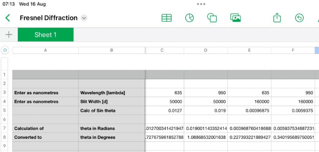
                    Regarding the slits … Could some kind soul please check my homework ?

                    .

                    4-46.jpeg

                    .

                    MichaelG.

                    #656712
                    Michael Gilligan
                    Participant
                      @michaelgilligan61133

                      This is a good overview of optical filters: **LINK**

                      https://www.edmundoptics.co.uk/knowledge-center/application-notes/optics/optical-filters

                      General warning: The clever stuff can get insanely expensive

                      MichaelG.

                      #656736
                      S K
                      Participant
                        @sk20060

                        That Olympus web site makes a false, or at least over-simplified, claim or two. It's not the case that if a slit is wider than the wavelength of light then the light passes without any diffraction. Every photographer, with their macroscopic irises, sees this in practice. In fact, even one edge (no "slit" at all) will cause diffraction.

                        #656741
                        Michael Gilligan
                        Participant
                          @michaelgilligan61133
                          Posted by S K on 16/08/2023 13:09:09:

                          That Olympus web site makes a false, or at least over-simplified, claim or two. It's not the case that if a slit is wider than the wavelength of light then the light passes without any diffraction. Every photographer, with their macroscopic irises, sees this in practice. In fact, even one edge (no "slit" at all) will cause diffraction.

                          .

                          … Which is basically what I had in mind when I suggested that your ‘slits’ might be too wide to be acting as slits angel

                          The big difficulty is choosing exactly the right few words, on a lively forum, to succinctly convey what one is thinking.

                          MichaelG.

                          #656743
                          S K
                          Participant
                            @sk20060

                            Whatever.

                            I haven't explicitly checked your math, but the results look reasonable (and of course it shows that diffraction is occurring).

                            #656750
                            Michael Gilligan
                            Participant
                              @michaelgilligan61133

                              Thanks

                              I will proceed with what I was hoping to do … and only sulk if the maths proves to be wrong after all wink

                              MichaelG.

                              #657269
                              SillyOldDuffer
                              Moderator
                                @sillyoldduffer

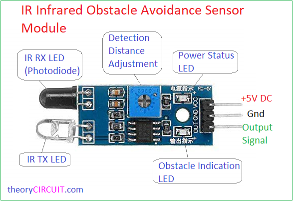
                                I set up an experiment to test the performance of the Arduino Infra-red Obstable detector I'm using to measure the period of my pendulum. One of these modules, with the photodiode and IR LED extended on leads:

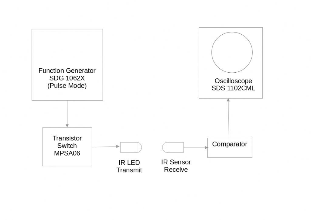
                                The test set-up is a 100MHz oscilloscope and a 60MHz Function Generator. The Function Generator is set in pulse mode, and it's output was connected to an MPSA06 transistor used to switch the IR LED on and off. To keep light out the IR LED and IR sensor were mounted inside a brass tube made on my lathe. (It's not all electronics!_

                                irtxrx.jpg

                                The arrangement lets me pulse the IR LED over a wide range of pulse widths and repetition rates and to measure how accurately the comparator responds to the detected signal.

                                Results are more complicated than expected.

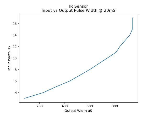
                                The shortest input pulse that can be detected depends on the repetition rate, this graph is for input pulses repeating every 20mS:

                                comparitor20.jpeg

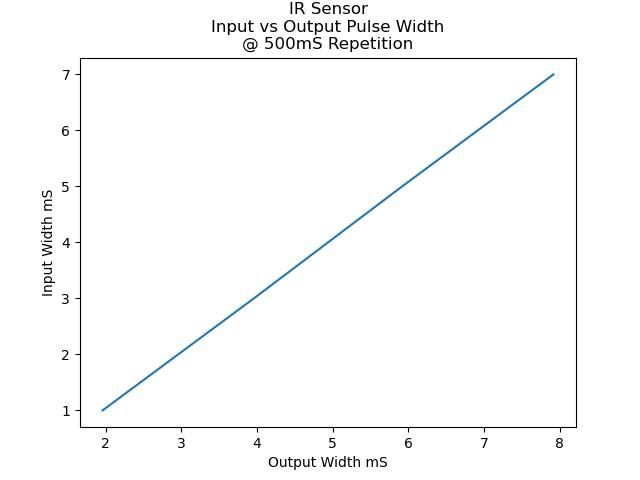
                                Although the comparator switches on quickly, 9.4uS after the transistor base is switched, it can take a long time to turn off after the input pulse ends. Next graph for slower millisecond pulses repeating every half second:

                                ir500.jpeg

                                Good news, no no sign of noise being introduced by the IR beam. Next step is to break the beam with a real bob and look for noise due to diffraction as the bob flies slowly through the beam. And to buy a Sharp opto to see how that fares.

                                Bad news, that the comparator stretches pulses means my relative amplitude calculation must be off because the sum is based on the length of time the beam is broken. Probably harmless because relative amplitude is only used to detect an arbitrary trigger point.

                                In doing the experiment I noticed yet again that sunshine causes real trouble.

                                Conclusion: the beam sensor is flawed, but not badly enough for me to rush to upgrade it. The way the beam sensor misbehaves when pulsed electronically doesn't explain why my clock rate wanders. I don't expect diffraction to explain it either, because surely any error diffraction causes must be constant?

                                I may take even more radical steps to keep sunshine out of my clock.

                                Dave

                                #657271
                                Michael Gilligan
                                Participant
                                  @michaelgilligan61133
                                  Posted by SillyOldDuffer on 20/08/2023 22:10:39:
                                  .

                                  […]

                                  I may take even more radical steps to keep sunshine out of my clock.

                                  .

                                  Don’t worry, Dave … Winter will be here before you know it angel

                                  MichaelG.

                                  #657282
                                  S K
                                  Participant
                                    @sk20060

                                    It's interesting that the detector is black or near black, presumably forming a white light filter.

                                    Since you are pulsing the transmitter, did you trigger the scope on that pulse signal and observe jitter in the delay between that and your output? That jitter is the real noise of interest, as it would directly contribute to your period measurement S.D.

                                    You want to use whichever output edge has the lowest delay / lowest jitter relative to the input signal (e.g. using your pulser). On the Sharp, that was the falling edge. Either ignore the other edge or only use it for non-critical functions.

                                    Diffraction of a single edge is probably a smaller problem than the shadow moving across the non-zero sensor width. But either may contribute to jitter due to it causing a shallower slope of the photodiode signal, i.e. worse noise performance than if you use the pulser. You have access to the photodiode directly if you are in a position to measure it.

                                    Again, I believe that your wandering in the cumulative timing error plot is substantially a random walk due to the summation of random period deviations. (Other sources will be due to temperature, etc., but that would add to the random walk.) You can simulate this very easily: Just produce a thousand (or whatever) normally-distributed numbers generated using your S.D. value and see how that wanders when accumulating them. No need to program, even: a spreadsheet can do this pretty trivially. Of course, you should re-run that a number of times to see how each run randomly differs.


                                    Edited By S K on 21/08/2023 01:14:33

                                    #657284
                                    Michael Gilligan
                                    Participant
                                      @michaelgilligan61133

                                      Whilst, obviously, we cannot be sure that all similar-looking items are identical … it is probably worth noting the description given here: **LINK**

                                      https://www.ebay.co.uk/itm/262723014158

                                      … and also the feedback:

                                      “2 out of the 5 had faulty LED emitters, would trigger from the IR from other modules though.”

                                      [ I’m guessing that’s a soldering problem ]

                                      MichaelG.

                                      Edited By Michael Gilligan on 21/08/2023 06:14:05

                                      #657285
                                      Michael Gilligan
                                      Participant
                                        @michaelgilligan61133

                                        Possible spec.for the receiver diode:

                                        **LINK**

                                        10 x 5mm LED Infrared Receiver 940nm

                                        MichaelG.

                                        .

                                        Edit: __ and, assuming that we may wish to experiment with the optics, a proper data-sheet for the Vishay one

                                        https://docs.rs-online.com/175a/0900766b80de9fc1.pdf 

                                        Edited By Michael Gilligan on 21/08/2023 06:49:43

                                        #657294
                                        Joseph Noci 1
                                        Participant
                                          @josephnoci1

                                          Maybe I missed the boat here, but seems to be a lot of messing about with opto-detectors and their 'failings'…failing I suspect mostly from sensor choices and implementation.

                                          I am using as another reference against my pendulum angle sensor a opto detector at around BDC, the OPB960-11.

                                          OPB9x0-xx

                                          It has the comparator built in.

                                          They are available with slits of 1.27mm down to 0.25mm – I used the 0.25mm both sides ( OPB960-11)

                                          This has a propagation delay of 5us with very low variance, available with open collector O/P or totem pole, the latter giving rise and fall times of 70ns. Operating about 2 meters from large windows facing out, on a bright day, I find no effects from ambient light on pulse position/jitter, referenced to the 1PPS from my GPSDO.

                                          One thing with opto sensors – esp with pendulum activities , which take a long time to evaluate ( years…) – the optoLED brightness falls with time, which will affect the sensor characteristics. This cannot be fixed with an all-in-one sensor such as the OPB series. If this is a concern, an op-amp sensing the detector DC level out when sensor is open then is used to control the drive current to the led, ie, increasing led current so the detected level remains as desired….but I think before this is needed there are a few other pendulum issues to be resolved by all of us!

                                          Edited By Joseph Noci 1 on 21/08/2023 07:58:41

                                          #657326
                                          SillyOldDuffer
                                          Moderator
                                            @sillyoldduffer
                                            Posted by Joseph Noci 1 on 21/08/2023 07:55:52:

                                            Maybe I missed the boat here, but seems to be a lot of messing about with opto-detectors and their 'failings'…failing I suspect mostly from sensor choices and implementation.

                                            I am using as another reference against my pendulum angle sensor a opto detector at around BDC, the OPB960-11.

                                            It's often hard to follow forum threads because after someone makes a point like as not many other unrelated posts intervene before it's addressed. Confusing

                                            This one touches on my wandering clock rate, which SK (who is experimenting with a laser), believes is due to my basic beam and sensor. He could be right because, as part of the experiment, I deliberately chose to repurpose an Arduino module. I assumed the module would work reasonably well, and – so far – haven't proved it's unsuitable. Rather late in the day, I've run some tests and discovered the module has shortcomings!

                                            Having wondered if I could approach the performance of a 1922 Shortt-Synchronome with a home-made pendulum and modern electronics, I decided to see what could be done with hobby technology. The idea was that anyone who wanted to copy what I was doing could do so easily. My clock isn't best practice, hence much messing about from which I've learned a lot and kept myself interested.

                                            I've got a big list of improvements. Not least the TDc7200 TDC and OPB960-11.

                                            Dave

                                            #657335
                                            Joseph Noci 1
                                            Participant
                                              @josephnoci1

                                              If you want code for the TDC7200 just shout Dave – you can hack it for your needs.

                                              These threads keep one's brain young and agile – you have to be able to multiplex seriously to just keep up..

                                              #657340
                                              S K
                                              Participant
                                                @sk20060

                                                That OPB960 is a higher-power device (hence the lower stray light sensitivity, I assume) with a much narrower aperture than the Sharp. Looks interesting!

                                                Joseph: Have you measured the RMS jitter in that 5 us delay? Or what are you getting for your pendulum as a whole?

                                                What are people using or planning to use the TDC for?

                                                #657345
                                                SillyOldDuffer
                                                Moderator
                                                  @sillyoldduffer
                                                  Posted by S K on 21/08/2023 01:10:17:

                                                  It's interesting that the detector is black or near black, presumably forming a white light filter.

                                                  Since you are pulsing the transmitter, did you trigger the scope on that pulse signal and observe jitter in the delay between that and your output? That jitter is the real noise of interest, as it would directly contribute to your period measurement S.D.

                                                  You want to use whichever output edge has the lowest delay / lowest jitter relative to the input signal (e.g. using your pulser). On the Sharp, that was the falling edge. Either ignore the other edge or only use it for non-critical functions.

                                                  Again, I believe that your wandering in the cumulative timing error plot is substantially a random walk due to the summation of random period deviations. (Other sources will be due to temperature, etc., but that would add to the random walk.) You can simulate this very easily: Just produce a thousand (or whatever) normally-distributed numbers generated using your S.D. value and see how that wanders when accumulating them. No need to program, even: a spreadsheet can do this pretty trivially. Of course, you should re-run that a number of times to see how each run randomly differs.

                                                  I think the photodiode's black colour is more a nod towards filtering than effective! Better than nothing.

                                                  Yes I looked for jitter by triggering the scope on both input and output. I couldn't detect any jitter with either arrangement except on the falling slope of the output when the comparator is rapidly triggered by a short input pulses, say 3uS wide input pulses every millisecond. A 1mS wide pulse repeating every 0.5s doesn't cause any jitter.

                                                  On this module only the RISING edge is reliable, but it seems very good. I use the RISING edge to count period, and time the FALLING edge to guesstimate relative amplitude, which, fortunately, is less critical!

                                                  Good idea about Standard Deviation and random walk – I'll have a go later.

                                                  Dave

                                                  #657346
                                                  Michael Gilligan
                                                  Participant
                                                    @michaelgilligan61133
                                                    Posted by SillyOldDuffer on 21/08/2023 14:47:38:
                                                    .

                                                    I think the photodiode's black colour is more a nod towards filtering than effective! Better than nothing.

                                                    […]

                                                    .

                                                    I can’t prove it … but I presume that the curve at Fig.6 of that Vishay data-sheet is dominated by the optical filtering.

                                                    MichaelG.

                                                    #657350
                                                    Joseph Noci 1
                                                    Participant
                                                      @josephnoci1
                                                      Posted by S K on 21/08/2023 14:11:23:

                                                      That OPB960 is a higher-power device (hence the lower stray light sensitivity, I assume) with a much narrower aperture than the Sharp. Looks interesting!

                                                      Joseph: Have you measured the RMS jitter in that 5 us delay? Or what are you getting for your pendulum as a whole?

                                                      What are people using or planning to use the TDC for?

                                                      Jitter on the 5us propagation delay is not easy to measure – what do you reference too? Sometimes one has to trust the data sheet…Jitter measured on my pendulum? – you are joking, I trust….the design and electronics is very immature at this early stage, so its a matter of elimination and improvement as we go – chucking out all LM211/311 comparators – they take a fortnight to switch, and using LT1394 zero volt detector switches – really fast and stable, but thats how it goes, measurements to come 'much' later.

                                                      The TDC – is a device that measures accurately ( to the accuracy of a reference crystal clock) the difference between a START and a STOP pulse ( down to 2ns or so resolution) – the start being my rather accurate 1Hz pulse train from my GPSDO, and the stop pulse being the pendulum seconds pulse from the comparator. That delta is used to determine how accurate and stable the pendulum is, and feeds the ADEV computation in TIMELAB.

                                                    Viewing 25 posts - 451 through 475 (of 502 total)
                                                    • Please log in to reply to this topic. Registering is free and easy using the links on the menu at the top of this page.

                                                    Advert

                                                    Latest Replies

                                                    Viewing 25 topics - 1 through 25 (of 25 total)
                                                    Viewing 25 topics - 1 through 25 (of 25 total)

                                                    View full reply list.

                                                    Advert

                                                    Newsletter Sign-up