If you want to be understood, you will have to do better. Until then, I'm just going to presume that your idea, whatever it is, will most definitely suffer from the sorts of flaws that I've described.
Over and out.
…
A logical error I think SK : where I come from ignorance of the law is no excuse!
I know what Michael means, and might try it. Or a variation. On a raspberryPi with a camera module fitted, the program libcamera-still allows long exposures. If, in the dark, I open the shutter and flash an LED at the bob once every millisecond, then close the shutter after 1 period, I should get a single exposure showing where the bob is at each flash. The frame rate doesn't matter, because the frame is only read once per beat. Should give a decent measure of actual amplitude because the bob effectively stops at the end of each swing to be photographed.
Is that what he meant, really? There was talk about how the bob is motionless at its extremity, and claimed or implied that he could capture that motionless bob (how was my question).
If you use a continuous longer exposure, you could look for the extremity of a blur (but not a frozen flag). Flashes will risk missing the extremity and/or if close enough will appear as a blur too.
Anyway, I've already done this, as I said, looking precisely for the extremity because I wanted to do a Q finding. I did it with 240 Hz frames instead of longer ones, but that's not important. With all my pixel-peeping holding the camera inches from the pendulum, I was still only confident of ~0.5mm resolution of the extremity of the pendulum's motion. Can better be achieved? Probably some, but dreams of <=10 microns won't be easy.
Is it possible that computers are not the way forward to the Utopia of pendulum timrkeeping? They seemed to offer foolproof speed-of-light control.This clearly is not so. Perhaps a separate Pi for each function may help. Electrical escapements and impulsing (without electronic help) are a help. Other problems were solved years ago with isochonous pendulums. Are computers really helping the timekeeping?
We can try to measure better, impulse better, etc., but in the end, the pendulums are in control. 😄
Does electromechanical impulsing and Hipp toggles have equal status with electromagnetic and optical means?
Is physical compensation, e.g. for temperature, more "pure" than entirely-detached measurement and computational compensation? —-
I would go with whatever works best, but look at the present discussion on " optical means "
Computers throw up their own complications. Fedchenko's sensing/impulsig coils would seem be the way to go.
dave8
Edited By S K on 14/08/2023 01:00:12
…
It's why precision pendulum technique is so interesting!
I'd be very surprised if any mechanical system outperformed a light beam or magnetic detector. The advantage of the electronics systems is they react orders of magnitude faster than a mechanical trigger, and they don't absorb any of the pendulum's energy. They're much less intrusive.
Far from perfect though! But keeping it in perspective, we're discussing noise, that is small deviations from ideal behaviour, detected by electronic methods. I'm worried not because my pendulum is obviously badly behaved, but because I don't know how much of the noise measurement is genuine pendulum misbehaviour, and how much is sensor error.
Various problems with Fedchenko for perfectionists. He used a permanent magnet on the bob to excite current in a coil as the bob flew past BDC-ish. The resulting current hump triggers an electronic circuit not much different from the optical equivalent. Not clear to me that magnetic noise performance is better than optical noise performance. And a problem having a magnet generate current is that it takes energy from the bob, and replacing it with an impulse disturbs the bob slightly, causing noise!
I don't see technologies as being more pure than others. In my view, the one that does the job most effectively is the best.
Thanks Michael for the description of the camera proposal. It may be worth putting some numbers on what can be achieved with conventional optos.
Some time back I posted here (different thread that I can't find) some results I measured on repeatability of the Sharp opto interrupters. I measured these using the CNC mill to make small slow movements and using the opto output to drive the probe input of the controller. A little macro to take repeated measurements which were exported for analysis. Basically I was getting a standard deviation of less than 0.2 microns on repeated approaches to the same position, in the dark and with constant supply voltage.
I referred earlier in this thread that Bateman's clock achieves better than 1 second of arc precision in swing amplitude, using "home made" optos. For a ~1metre pendulum this amounts to a precision of ~5 microns in estimating the peak. Noting that the velocity of the pendulum is going through zero at the maximum deflection and so the waveform seen by the detector will have very slow edges, this isn't bad at all.
Yes, the opto sensor is affected by ambient light and voltage variation but I think these results give some sort of scale to what we are trying to achieve.
Given that the sensor in an opto is in a sense a "one pixel camera" then perhaps some experiments with a webcam lens and a conventional photodiode would be useful?
Various problems with Fedchenko for perfectionists. He used a permanent magnet on the bob to excite current in a coil as the bob flew past BDC-ish. The resulting current hump triggers an electronic circuit not much different from the optical equivalent. Not clear to me that magnetic noise performance is better than optical noise performance. And a problem having a magnet generate current is that it takes energy from the bob, and replacing it with an impulse disturbs the bob slightly, causing noise!
I don't see technologies as being more pure than others. In my view, the one that does the job most effectively is the best.
Dave
I've had a reasonably close look at Fedchenko's circuit – actually it's a "blocking oscillator" that has almost zero bias most of the time so doesn't do anything. It's input impedance will be very high as the input transistor is essentially "off". The coil voltage gives it just enough forward bias, taking hardly any current, to push the transistor to conduct at which point positive feedback takes over to apply a short pulse to the coil in the same direction as it is moving. On the other swing the sense of the induced voltage is opposite and the transistor just biases off more. So I suspect the loss is negligible and the impulse as central as it practically can be. I've recently learned to use Spice so must try simulating it!
That’s a very impressive performance you recorded for the Sharp Opto, John
… I would be interested to see the the raw data, if you have it to hand.
I am embarrassed to admit that I may not have fully understood your test procedure:
Are you saying that, if we call the true position zero, almost all your individual measurements were within the range -0.0006 to +0.0006 mm ? [i.e. zero +/- three standard deviations] … if nothing else, that’s an amazing performance from your CNC system.
Regarding the camera idea: many alternative lenses and sensors are of course available … my ten micron resolution is just an example, using a very modest webcam to demonstrate the concept.
I've had a reasonably close look at Fedchenko's circuit – . . . .
And all done without a computer!
dave8
Arguable that Fedchenko's transistor circuit is a very simple computer, but all it does is keep the pendulum swinging, it doesn't monitor or control amplitude and it tells you nothing about period.
A few updates and thoughts, including about the impact of diffraction and camera resolution:
I measured my slit to be 160 um wide. Project the laser through it, and it becomes painfully clear how serious a problem diffraction can be. Of course, a single edge, e.g. a flag, experiences diffraction too. This means that a hard edge will not yield a hard cut-off of the light. Instead, there will be a soft reduction in light that depends on the distance between the flag and sensor and the speed of the flag. The bottom line is that whatever flag or slit, etc., is used, it should be positioned as close to the sensor as practical. Even a centimeter is a lot!
Also because of diffraction, the use of a lens to magnify the motion of a flag will not work as well as hoped unless the distance between the flag and sensor is similarly short.
About the camera idea: For best resolution, I'd suggest directly projecting a shadow onto the bare sensor (no lens). You will not likely find a lens that will deliver the sort of resolution you are seeking. All of them, even a "telephoto," would actually be a wide angle (relatively speaking) compared to the raw pixel resolution. For example, if a field of view of say 100 mm is projected onto a sensor 10mm wide, then each pixel views a region 10 times larger than the size of the pixel itself, e.g. instead of 10um, you only get 100um resolution. For a camera to deliver "pixel resolution," it would have to observe a total field of view no bigger than the camera chip itself.
Again due to diffraction, in the direct projection scheme, the sensor should be as close to the flag as possible.
Where can one find information about the Bateman clock? I've searched and came up pretty empty. Thanks.
Posted by Michael Gilligan on 14/08/2023 12:50:38:
…
… I would be interested to see the the raw data, if you have it to hand.
MichaelG.
On its way to you Michael, together with a write-up, by email.
.
I have read it twice this evening, John … and I remain astonished
The biggest ‘take-away’ for me is that the Sharp opto is seriously compromised by ambient light,
[quote] It quickly became apparent though that even ambient daylight has a large effect on precision, so it is best to assume that the sensor should be shaded as well as possible. [/quote]
Left to its own devices [so to speak] the performance is quite amazing; and this, of course, is using a simple IR LED that provides ‘flood-lighting’ !!
All the clever stuff must therefore be credited to the sensor itself … Mmm !!
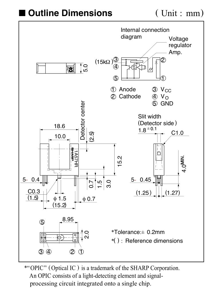
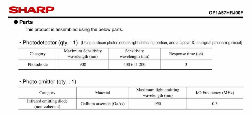
I have the package drawing, and have purchased a small quantity of these devices to play with study
… in due course [which may be a while yet] I will try to better understand the optics.
Arguable that Fedchenko's transistor circuit is a very simple computer, but all it does is keep the pendulum swinging, it doesn't monitor or control amplitude and it tells you nothing about period.
Dave, don't get me wrong . I'm not against computers, but I wonder whether the sometimes spurious results thrown up might over say a 1-year run, ruin your clocks performance. I doubt that Fedchenko's simple single transistor circuit would suffer from this too much. Maybe testing your pendulum's performance with a separate device outside of your clock might give better results? A timing of ticks over a long period is all thats needed.
I made a new, smaller slit, this time about 50 microns wide. This is not very hard to do, at least if you have access to a stereo microscope and some fine tweezers. At that scale, it's not easy to measure, though.
I attached it to half of a Sharp opto (the receiver, of course) and hit it with the laser. Unfortunately, it seems that I destroyed it, either electrically somehow or via the laser. There was a peculiar effect which looked a bit like "latchup" (a phenomena that can happen when a flash of strong light hits an IC), but I can't prove it was ever working, so I can't be sure it was the laser either.
I then rigged up a Sharp opto (the whole opto) with the slit, and ran it normally (no laser). The opto's receiver has a domed lens, and it was not difficult to align the slit such that it worked. My goal was to measure the pendulum's RMS period variation, hoping that the slit may improve timing resolution. However, this did not work either, as the RMS value actually shot up. I have to try again, with and without the slit, with all else being equal, before I can be sure. The reason I'm uncertain is that my Agilent counter is infuriatingly cranky. I don't think it likes the very long periods.
If the Sharp really delivers lower time resolution with the slit, I'd theorize that a drop in signal to noise ratio due to less light getting through may be to blame. In that case, I'll try the laser again, maybe with a pinhole instead of a slit.
Also, it occurred to me that a slit would reduce ambient light impingement on its own, in this case by more than a factor of 10. Of course, it reduces the signal too, possibly to a net disadvantage.
I made a new, smaller slit, this time about 50 microns wide. This is not very hard to do, at least if you have access to a stereo microscope and some fine tweezers. At that scale, it's not easy to measure, though.
I attached it to half of a Sharp opto (the receiver, of course) and hit it with the laser. […]
.
You have my sympathy, but …
[given what you have already demonstrated about diffraction], I have to ask why ?
Because diffraction due to the slit doesn't matter if the slit is directly in front of the opto's lens. The lens is about 1.5mm wide, while the slit is a tiny fraction of that, and is maybe 1mm in front of it. The photodetector is hard to see, but it's also about 1.5mm wide. So any light diffracted by the slit will be collected by the lens and seen by the photodiode anyway.
Diffraction due to the flag does matter (it softens the flag's light cut-off) if it's much further away, but that's a different problem.
By the way, I see you want to focus your lens very, very close. You will probably need to modify it to include an extension to be able to do that.
Please don’t worry about my lens … the optical requirements are well known to me and I was only describing adjustments that I have previously made [in the hope of attracting sufficient interest that someone might help me with the programming to make it work as a switch].
I was curious about the laser and the slit because your laser is red
The Sharp opto is an IR device and I think it reasonable to assume that the clever people at Sharp would have designed its optics accordingly.
My question was part of my general quest for understanding. … So thanks for answering.
I redid the RMS period measurements on the Sharp opto, with my 160um slit and without.
Without slit: 4.08 us RMS
With 160 um slit: 12.6 us RMS
I should retry the 50 um slit again, but it was even higher, and I'm confident in this result already: using a slit makes it worse, presumably because less light entering the photodetector results in a worse signal to noise ratio.
My pendulum is completely free, so I have to launch the pendulum by hand, and it's difficult to do so without introducing at least some wobble orthogonal to the pendulum's normal swing. Therefore, I normally wait 10 minutes or so for it to settle before taking data, and I check for any remaining wobble before data processing. However, I noted that the detector with slit appeared to show wobble of the pendulum more strongly and clearly as a decaying oscillation. I don't yet understand why this could be more evident with the slit, so if anyone has an idea, please let me know.
As for the laser color, etc.: The "lens" is just a dome of plastic with a rather rough and cloudy surface finish. It's transparent aside from the poor finish, of course, so it will transmit red light with ease. Although the sensor is almost certainly not silicon (silicon photodiodes are completely insensitive to IR light), an IR sensor will be just as sensitive if not more to red light, as the shorter wavelength (higher energy) will cause the liberation of electrons even more easily. I don't think any of this has very much to do with diffraction caused by the slit.
My next step will be to retry the laser with the Sharp receiver. I will probably use a pinhole instead of a slit this time, to reduce the net light exposure a little further, while still presumably being stronger than the IR transmitter.
Arguable that Fedchenko's transistor circuit is a very simple computer, but all it does is keep the pendulum swinging, it doesn't monitor or control amplitude and it tells you nothing about period.
Dave, don't get me wrong . I'm not against computers, but I wonder whether the sometimes spurious results thrown up might over say a 1-year run, ruin your clocks performance. I doubt that Fedchenko's simple single transistor circuit would suffer from this too much. …
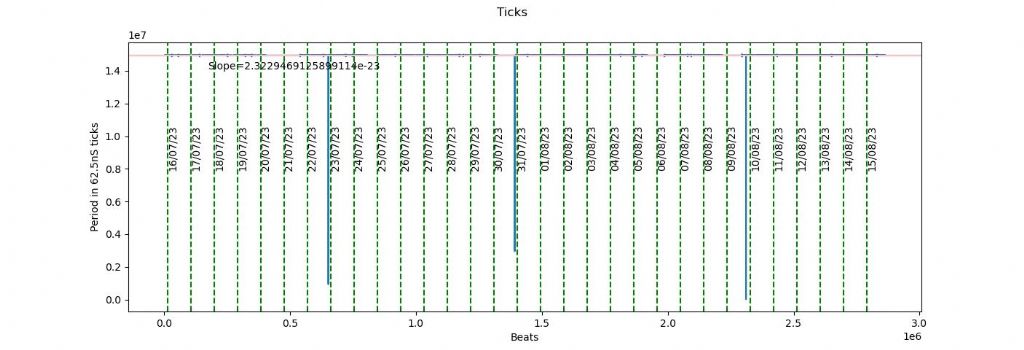
Spurious sensor readings are causing my pronblems rather than the computer as can be seen in this graph, where 3 giant errors cause the clock to jump:
I don't know what caused them. May be a coincidence they all occur just before midnight.
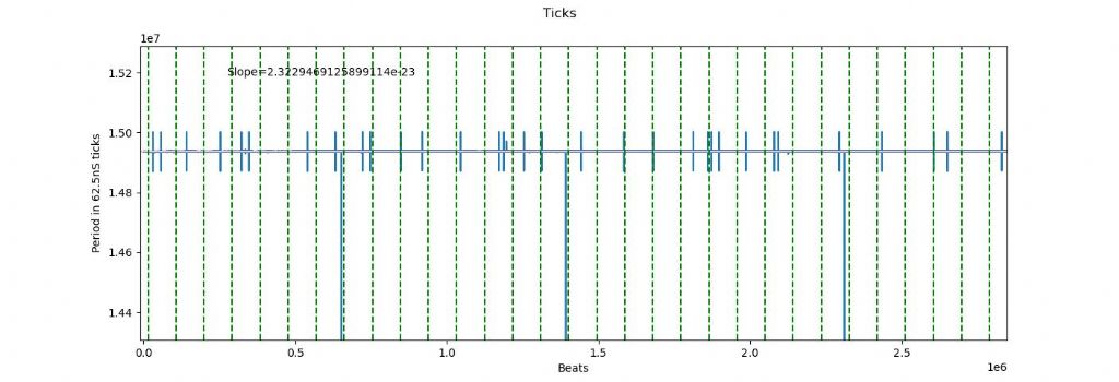
Zooming in on the data shows thirty odd more much smaller anomalies:
Although the smaller glitches balance out, they shouldn't be there. Best thing would be to find and fix the cause, but I've thought of filtering them out in software. Hard to find the cause of only 40 apparently random errors in 2.9 million readings, so it's tempting!
I can't get away from using a computer because I'm experimenting with a statistical clock. In this experiment the actual pendulum period doesn't matter provided all swings are normally distributed. Instead, detecting a swing causes the microcontroller to calculate and count what the period should be after compensating for temperature and pressure. The period calculating formula is derived from statistical analysis of a long pendulum run during which the pendulum is compared with a much better clock. (Bog standard NTP at present but I can also use GPS).
Despite progress, I'm not getting the precision I long for!
On the graph above the straight green line shows what the clock should be doing, i.e tracking NTP within about 100mS. The blue line shows my clock is wandering, and other graphs show the rate changes are not temperature or pressure related. The wandering blue line is bad news – straight lines are easy to compensate, random wandering is a horrible mystery. Roughly:
Gained 23 seconds in 7 days, then
Lost 2 seconds in 2 days, then
Gained 8 seconds in 9 days, then
Lost 1 second in 8 days, then
Gained 1 second due to a sensor error, then
Lost 14 seconds in 6 days.
After a month, never been more than 29 seconds wrong, and is currently only 17 seconds fast, not awful except I'm hoping for milliseconds per year, not half a minute per month! In theory my clock is working brilliantly: in practice it's below average. Unfortunately the experiment requires I persist with the computer!
A pretty bad trend, getting exponentially worse! I'm sure glad I didn't buy that 3um slit I was eying (well over $100)!
Dave: I don't know about the glitches, but the clock vs. NTP time plot looks a lot like a typical random walk due to the accumulation of minor random errors. My suggestion is to direct your attention to improving the period measurements. Get a few of the Sharp optos, maybe. They are pretty good and may improve things a lot.