As promised, John …
This is very simple stuff, but if I have glossed-over anything, just shout
.
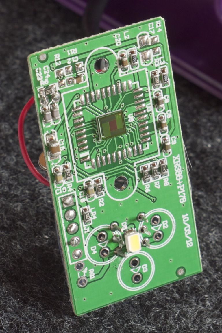
Here is the board from a little webcam:
.

.
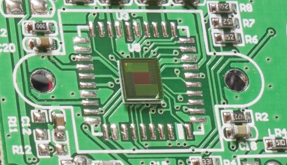
I removed the lens assembly [ you can see its footprint] to reveal the sensor chip:
.

.
The small brick-red rectangle is the active area.
I have never managed to identify the actual chip, but it appears to be a 1/9” sensor with 640×480 active pixels on a 2.5 micron pitch.
All of which is largely irrelevant, except that it means the focal length of the lens is small, and therefore it can be focussed over a wide range with only short adjustments.
The camera is UVC [Universal Video Class], which means that it will run ‘driverless’ on most any modern computer.
Conveniently, that includes the Raspberry Pi, on which it works nicely with the GUVC application.
.
Now … [assuming that we have the complete camera before us] first remove the decorative ‘trim ring’ and confirm that the lens screws freely in and out.
Plug it into your computer of choice, with whatever viewing software you have, and adjust the focus so that a -1/4” wide target just over-fills the frame-width … at which point, each of the 640 pixels is representing 10 microns.
[sorry about the mixed units, it just works out tidily that way].
You now have a microscopic view of an adequately wide field, with approximately 10 micron resolution … this could, of course, be meticulously calibrated, but I see no need in the present application.
… I can leave you to calculate how good that would be in milliradians at your chosen radius.
.
Your mission, should you decide to accept it, is to find a way to grab the data, and then apply whatever logic to trigger an impulse at the chosen point whenever the swing has decayed by whatever amount you choose.
Matthias Hipp will be honoured, I will be grateful, and this guy should be impressed:
**LINK** : http://www.rogerj.co.uk/clock.htm
MichaelG.
John Haine.


