Posted by Michael Gilligan on 06/08/2023 02:43:15:
Posted by S K on 05/08/2023 23:19:52:
[…]
if true, it seems that there's a lot of payoff to building a better opto system, especially if you are interested in short-term effects.
… spot-on [
It's the "if true" question that's captured my interest & why I'm developing an experimental pendulum.
A good way of solving problems is to copy previous work, doing better by implementing best practice in new ways. Knowing how much weight a bolt needs to support, choose a standard size and type. Don't design a new fastener or anything else unless essential. Avoid Experiment.
I'm taking an experimental approach. If I only wanted to build the best possible clock, it wouldn't have a pendulum!
My interest is in seeing how good a pendulum clock I can make with modern methods, a hobby. So far measured two prototypes & measuring is difficult in itself. The second prototype tackled flaws revealed by measurement.
An important principle is that I fix big problems first:
Basic mechanical issues, mainly in my over-simple poorly-made suspension
Changing temperature causes major errors that must be managed
A surprise, changing humidity caused significant errors in a carbon-fibre rod used experimentally as a combination rod and suspension spring. I believe humidity alters the rod's flexibility rather than its dimensions.
air-pressure causes small deviations, and has to be managed too
All that done, I still have detectable errors. In particular my pendulum is 'noisy', that is its period varies slightly beat by beat. In a mechanical clock, the escapement and impulse are likely suspects. My escapement is an Infrared beam. and the impulse is applied by an electromagnet.
Focussing on the electromagnet, it's clear from my measurements that over powerful impulsing always disturbs period. More, is it best to apply the smallest possible impulse on every beat, or to minimise shock by applying a larger impulse every 'n' beats, and letting the pendulum swing free as much as possible? My results are contradictory: first prototype was best impulsed every beat, but the second works best impulsed every 'n' beats. Don't know why.
Moving on, I believe most of the noise in my pendulum is due to a mistake! The sensor holder is too short & the IR detector isn't triggered until the bob is a few degrees past dead centre. No excuses, George Airy proved about 1830 that the impulse must be applied at dead centre, but experimented with a gentle magnetic pull at top. Having decided George was right, I messed up the 3D-CAD model so the real clock is wrong.
Next step is to rebuild the clock, hard work because I shall add the vacuum plumbing too. Delayed due to illness.
However, at this stage, I've no evidence that the IR beam in my clock is causing any trouble. As the beam uses ordinary components, wouldn't be surprised to find noise due to mismeasuring, but so far not detectable. Why not? I posit any beam outperforms a mechanical escapement simply because no force is applied to the pendulum. Also, beam noise may not matter if the electronics are reasonably consistent. Beam engineering can't be ignored – was necessary to shield the IR receiver to avoid false triggering due to light & reflections.
If the next rebuild shows the beam is causing trouble, that part of the clock will be upgraded. But I've plenty else to worry about before needing to spend time and money on it. And I want to measure just how good or bad a basic IR beam is before moving on.
FGPA and similar suggestions aren't attractive yet. At present, applying FGPA to my clock would be a lot of effort for not much return. I have to find and fix big errors first. I'll die happy if my clock performs so well that FGPA is needed to improve it.
Quick explanation of FGPA! A digital computer can emulate any logic function by applying a sequence of instructions to data. Very flexible because the instructions can be changed at any time. Not all rosy though. Though fast, the electronics in a computer have to do a lot of time consuming work – read next instruction, decode & execute. Therefore plain electronics are faster than a computer programmed to do the same job.
Unfortunately hard wired electronics only do one job and are expensive to design, build, and debug. Change very difficult.
A Field Gate Programmable Array is a good alternative: a gigantic chip stuffed full of logic circuit blocks that can be interconnected in any way. Connections between blocks are programmed, perhaps by blowing fuses to disconnect unwanted circuits, producing a configuration that does a single complex function at high speed.
Blank FGPA are mass-produced and applying them to a problem is more like computer programming than assembling conventional components. Very common now for electronics to be built from a mix of microcontrollers, FGPA, &specialised chips. The combination is fast, affordable, and mostly programmable. A few clever folk understand it all, but development is mostly done by specialist teams. I'm probably too old to tackle FGPA now, but it's good stuff.
Posted by Michael Gilligan on 06/08/2023 02:43:15:
Posted by S K on 05/08/2023 23:19:52:
[…]
if true, it seems that there's a lot of payoff to building a better opto system, especially if you are interested in short-term effects.
… spot-on [
It's the "if true" question that's captured my interest & why I'm developing an experimental pendulum.
[…]
.
More power to your elbow, Dave !!
I am truly in awe of the work you are doing, even though much of it is beyond my comprehension.
.
That said … I will try to briefly explain why I was so supportive of theremark made by S K
It is possible to analyse and to control, the behaviour of a Pendulum in the Spatial Domain or the Time Domain [treat that as an ‘inclusive OR’ for now] … but if your ambition is to get the time-keeping right, especially the short-term accuracy, then it seems intuitively obvious that anything ‘spatial’ should be as accurately monitored/controlled as it reasonably can be. Extracting spatial data by devious calculation seems a little too much like a complicated ‘self referential’ process, when it could be done directly instead.
Sorry … I’m probably not making much sense there: I don’t have the Maths to demonstrate what I am trying to say.
Lurking somewhere, there is a little demon whispering ‘Garbage in >> Garbage out’
I was intrigued by the statement above that detecting the pendulum with IR had no effect on the pendulum. It seemed to me that if photons of IR are hitting it they must exert a force (however tiny) on it. However some googling later I find that photons have no mass, but they do have momentum. This is getting too deep for me, I reckon people who claim to understand quantum theory etc should go and get treatment. Perhaps someone who understands particle physics can tell us, does impinging an IR beam exert a force on the pendulum.
I don't expect this to be high on SOD's list, by the time this matters I think even he will be satisfied with his pendulum
Posted by Michael Gilligan on 06/08/2023 15:48:57:
Posted by SillyOldDuffer on 06/08/2023 12:12:47:
Posted by Michael Gilligan on 06/08/2023 02:43:15:
Posted by S K on 05/08/2023 23:19:52:
[…]
if true, it seems that there's a lot of payoff to building a better opto system, especially if you are interested in short-term effects.
… spot-on [
It's the "if true" question that's captured my interest & why I'm developing an experimental pendulum.
[…]
.
…
Sorry … I’m probably not making much sense there: I don’t have the Maths to demonstrate what I am trying to say.
Lurking somewhere, there is a little demon whispering ‘Garbage in >> Garbage out’
MichaelG.
No need to be sorry, I have the same reservations. It's all too possible that some of the assumptions behind my ideas are wrong.
I lack the maths and evidence to prove it's all good, and, as I'm operating on the bleeding edge of my understanding, someone who knows could turn up and demolish me. I'm hoping to get more conclusive evidence.
The case is open – so far no-one is convinced, but no-one has raised a rock-solid objection either. Could go either way, but I am nervous.
A concern about measured opto-interrupter performance is that one can't quite be sure it's just the opto-interrupter being noisy, or how much more potential there may be with an improved one. Unfortunately, the Sharp module does not provide access to the photodiode, but only to the digital output.
So, I've ordered a silicon photodiode and a laser module with which to do a few tests. The photodiode is quite small, only 1mm across, and it has a low capacitance and hence a high speed . I'll probably reverse-bias the diode and just look at the signal across a load resistor on a scope.
It only cost about 100 times that of a Sharp opto. 🙄
Anyway, the parts should be here in a few days, and I can use my gravity pendulum as a test subject.
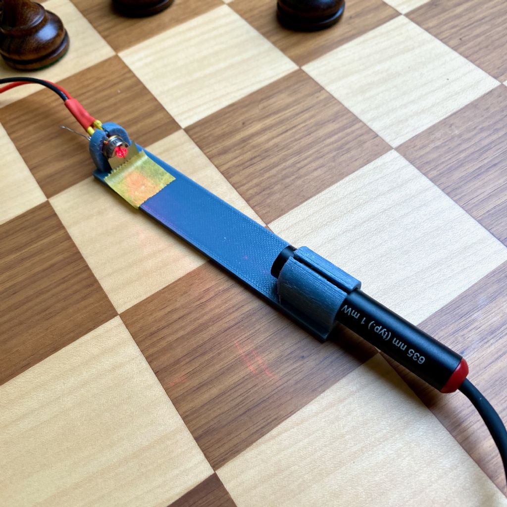
I have some results – mostly anecdotal thus far – from testing a laser and photodiode combination. The setup is seen below.
The photodiode (Thor Labs FDS010) is silicon, and was selected for its small active area of 0.8mm^2 (1mm diameter). The small area means a small capacitance and hence high speed (quoted 1ns rise/fall time, presumably with a 50 Ohm load), plus a flag should spend less time traversing the surface during a pendulum swing.
The laser is a Thor Labs PO204, 635nm, Class 2 (<=1mW), with a lens and a round beam of about 3mm across. This wavelength is somewhat close to the photodiode's peak wavelenth sensitivity of 730nm. A Class 2 laser is generally safe, and is as bright as likely needed for this application, as it is indeed very bright: absolutely do not stare into the beam (with your remaining good eye)!
I have mounted a slit, made from two razor blade shards, vertically in front of the photodiode (the mount is very cheesy, but it works for now), with explanation below.
The photodiode is being run with a 5V reverse bias purely for convenience (10-20V would be better). A 380 Ohm load resistor is used to provide a detectable voltage while still maintaining a fast speed of operation.
I used my gravity pendulum as a test vehicle, and an oscilloscope to observe the output. The combined capacitance of the photodiode and the scope probe is slightly under 20pF. In combination with the 380 Ohm load resistor, this should be a very fast sensor.
But, without the slit, the rise and fall times were about 50 ms! This is very long, and at first I was confused (also by the linear slewing that was observed), but the reason is simple: it takes about that long for the pendulum to sweep across the ~1mm detector. I predicted this effect notionally (hence the small detector), but my mistake was not calculating how bad it would be!
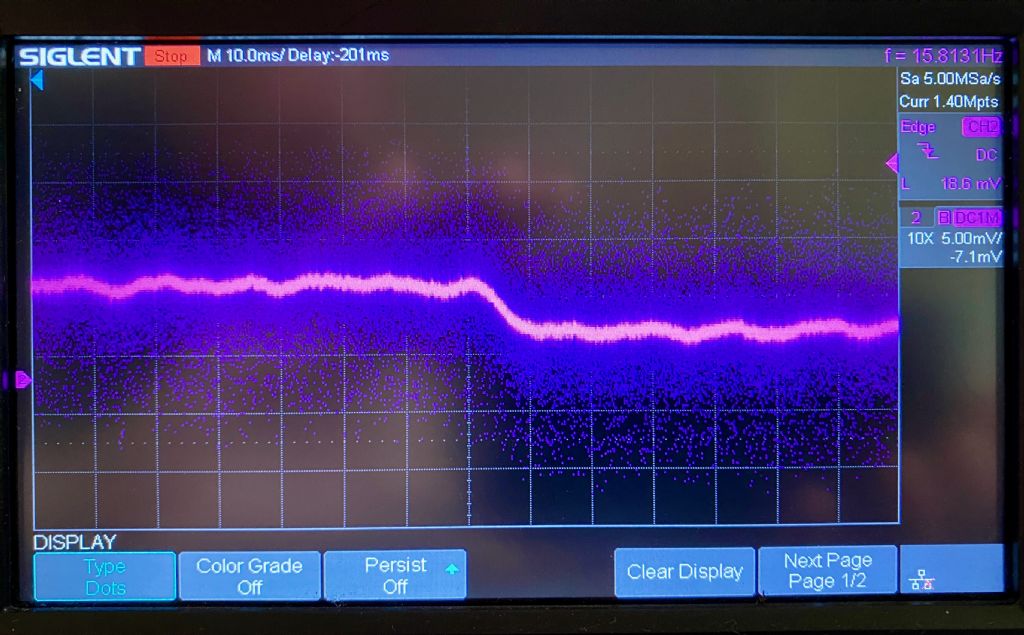
Using the slit (not measured, but it's pretty small) reduced this to ~7ms, which I still consider to be very slow. And since it blocks a lot of the light, it also reduces the signal amplitude considerably:
There's a fair amount of noise in the signal, which I should track down.
Here's the dilemma: Pendulums are just too slow for good timing! Even with a narrow slit, the rise and fall times are much slower than I was hoping. The problem is that the slope of the rise/fall times is slow enough for noise to cause a fair amount of jitter in a comparator's output.
At this point, I am not at all surprised at the ~5us RMS noise in the Sharp sensor's output, and it's not clear to me that much better can be achieved without trickery. For now, I don't recommend that people spend the money on the above sort of combination. But for those using the Sharp opto-interrupter, a slit in front of the photodiode may help. Also, it's best to detect the swing at BDC, where it's moving the fastest.
To be continued after I spend some time in thought. Some way to optically amplify the speed of the pendulum is needed. Any ideas?
…
Optically amplifying the speed of the pendulum is an interesting idea, but before attempting that is the signal from the diode being fed into a comparator or Schmitt trigger? (A Schmitt Trigger is a comparator with hysteresis, which can be advantageous.)
These electronic circuits compare two voltages. One input is a stable reference voltage typically set to 1/3rd of max signal. The other input is the signal from the detector. When the signal voltage is below reference, the comparator outputs nothing, but as soon as signal voltage exceeds reference, the comparator flips and outputs full voltage. Depending on the device, flipping from zero to maximum takes pico, nano or microseconds.
Coupled with a sharp beam the electronics detect the pendulum at a particular point in the transit, and the trigger is much faster than milliseconds.
Another possibility: I found a laser inferior to yours was much too powerful. So bright that the sensor was overloaded, causing odd results. Try attenuating the beam, perhaps massively.
If you pass a small diameter cylindrical mirror (polished stainless rod perhaps) through a beam the beam will rapidly swing through a large angle. A detector mounted at a suitable point will catch the flash as it swings through.
Ideally you need the beam constrained in width through a slit in the same orientation as the axis of the mirror. I’ve often used optical fibre to deliver the beam and catch the reflection.
I don't need a comparator yet. For now I'm looking at the analog output straight from the photodiode. What I want to know is what the photodiode's own signal is doing so I gain an understanding of what an op-amp, etc., would have to work with. (The photodiode is definitely not close to saturating.)
So: I increased the load resistor to 10k, which significantly increased the I-to-V gain, in order to compensate for the reduced illumination through the slit. I also narrowed the slit a little more. I think I could go narrower still with some care.
The net result at present is roughly 80 mV signal and about a 3 ms rise/fall time. The rise and fall times are currently dominated by the speed of the flag, which causes the voltage to rise as more of the photodiode is illuminated or fall as more is covered.
I tried to use my counter to compute an RMS value for the period, but it would not work reliably with this signal level, so an op-amp will be needed to make more progress. Adding a comparator, Schmitt trigger, etc., can speed up the edges almost arbitrarily, but while that looks good, it says basically nothing about timing resolution of everything that came before.
If the slit technique is the best improvement that can be made, I could buy a precise one. These are available down to 3um and probably lower, but they are quite expensive. With a very narrow slit, a more powerful laser might help too.
If you pass a small diameter cylindrical mirror (polished stainless rod perhaps) through a beam the beam will rapidly swing through a large angle. A detector mounted at a suitable point will catch the flash as it swings through.
I thought of this a while back, and proposed it in some thread here somewhere, but then I decided it wouldn't work. The reason is that a cylindrical mirror will widen the beam exactly as much as the lever arm extends, and the two kind of cancel each other. So yes, the beam may sweep 10x faster out at some distance, but it will be widened and dimmed by 10x too. No?
But now I feel like something along these lines could still work as long as the laser is strong enough. Maybe I'll print up another holder with an angle between the laser and sensor to just try it empirically. My flag is my rod, which is shiny enough. I wonder what an optimal angle would be? I guess 60 degrees sounds OK.
Dig a very deep hole in the floor under the pendulum. Have a flat front silvered mirror on the end of the pendulum facing down the hole. At the bottom of the hole mount your laser shining up and the sensor at its side.
Having thrown that improbable idea in, I'll retire for the night. Might work if you had a stairwell handy.
Some more thought about the cylinder idea: The beam is not uniform across its diameter, and it has a 2D Gaussian intensity profile. This doesn't matter if the beam is stationary and aimed straight at the detector. But if the beam is sweeping, and especially if it's spread out, the voltage on the PD will rise and fall as it's swept past because the intensity will be constantly changing. A pinhole or slit could constrain it, e.g. to a central area, but diffraction will just spread the beam out again into the same basic shape anyway. So I'm not sure it works again.
Duncan, are you proposing that the mirror will sweep a small angle? That has the same intensity profile problem, but it's lessened in that it doesn't spread the beam out like the cylinder does – only the laser's own divergence would occur. And you wouldn't even need to dig a hole: A vertically-mounted mirror (i.e., at the side of the rod) to reflect in the direction of swing would accomplish the same thing. Similarly, a prism or right-angle mirror could reflect the light from the side up the pendulum, too (that might be the most practical orientation). Interesting and more promising!
Having woken ‘in the middle of the night’ I need to get back to sleep … but must first thank you S K for taking the plunge and doing some practical exploration.
Another thought about Duncan's mirror idea: Unfortunately, if the baseline from the mirror to the sensor is the same as the pendulum's length, then it is no better than just flagging the end of the rod as normal. You would need a baseline much longer than the pendulum for it to make any sense. So I don't think it's very practical.
…The net result at present is roughly 80 mV signal and about a 3 ms rise/fall time. The rise and fall times are currently dominated by the speed of the flag, which causes the voltage to rise as more of the photodiode is illuminated or fall as more is covered.
…
Adding a comparator, Schmitt trigger, etc., can speed up the edges almost arbitrarily, but while that looks good, it says basically nothing about timing resolution of everything that came before.
…
This is very interesting because it challenges one of my assumptions, which is that a comparator triggers at a particular point of the bob's transit.
I assume that velocity of the bob is nearly constant. Therefore the sensor output is a regular series of voltage blips, all the same shape. It's advantageous to sharpen the blip edges and remove noise and reflections with slits, lens collimation, flags, and lasers etc, but what matters is that all the pulses are all the same shape. Then the instant that the pulse waveform rises above reference voltage occurs reliably at the same point on the slope every time, and that point relates accurately to the bob's position. Period is obtained by measuring the difference between the same point on successive pulses.
A comparator isn't just tidying up to look good, far more importantly these devices accurately detect a particular point on a voltage slope. After that, the very useful tidy up results from the comparator flipping rapidly after detection – comparators fire very quickly after being triggered, so the rest of the electronics don't have to worry about sensor characteristics.
What I'm describing isn't novel – it's how oscilloscopes work.
So I think the most important features of a beam detector are:
They detect much faster than the bob moves. (Therefore speeding the optical speed of the pendulum is unnecessary and likely to increase errors.)
The sensor output is regular, that is the shape of the pulse produced by the bob sweeping past the sensor is always the same. (This can be checked with an oscilloscope)
The trigger is reliable (Voltage regulate the comparator reference)
After triggering. the response must be fast, or at least with known delay, and the output as close to a square wave as possible (A comparator or Schmitt Trigger does this, ideally a type chosen to suit this application.)
Sharpening the shape of the sensor's output with slits, shielding, and collimation helps by improving rise time. Be interesting to set up a test rig and measure how much varying slit width moves the detection window of a comparator.
For what it's worth, not much, my efforts with slits were aimed at improving reliability. Beam systems are vulnerable to sunshine and reflections causing the apparent slope to vary, for example sunshine falling on the back of an IR sensor alters its sensitivity to IR entering properly through the front lens.
I'm looking forward to SK's next move. He's questioning things I've assumed which is always good. Entirely possible I've overestimated the performance of my beam system, and not noticed because bigger errors mask the problem. I went cheap and convenient rather than sophisticated, therefore likely better is needed. Not proven it needs fixing yet though.
Back to the flat mirror. Bouncing the beam off a mirror doubles the angular deflection, so if the mirror was fixed to the top of the pendulum and the laser and sensor were at the bottom it would double the deflection. However I wasn't being entirely hence reference to a deep hole. Something tells me that having a long optical path isn't good. The idea came from memories of ballistic galvanometer we were allowed to play with in physics lessons at school, and that's a long time ago.