Precision pendulum techniques

Advert

Precision pendulum techniques

Home Forums Clocks and Scientific Instruments Precision pendulum techniques

Viewing 25 posts - 226 through 250 (of 502 total)
  • Author
    Posts
  • #637585
    david bennett 8
    Participant
      @davidbennett8

      Dave, if you are using usb power for your coil, I am told the voltage can be very "noisy" Could this explain some of the results you see?

      dave8

      Advert
      #637595
      david bennett 8
      Participant
        @davidbennett8

        I believe the possible usb power problems only occur with mains powered units. Using a re-chargeable battery power pack with usb output should guarantee clean power.

        dave8

        Edited By david bennett 8 on 14/03/2023 06:14:32

        Edited By david bennett 8 on 14/03/2023 06:15:08

        #637610
        Martin Kyte
        Participant
          @martinkyte99762

          I’m not sure that noise in the usual sense would be a problem for impulse coil driving. The inductance of the winding and the magnetic circuit is going to filter out any higher frequency components. What I would be more concerned about is the stability of the 5V. Maybe a short test using a chunky battery and a 5V regulator would be more n order just to see if it makes any difference.

          If it turns out that USB power is an issue I would be inclined to have a go at driving the coil current with a current output buck regulator.(The ones developed for driving LED’s)

          Peak current is programmable by either a sense resistor if you build your own or by a trimmer pot. They do control current by switching techniques but the frequencies are in the 10s to 100s of kHz so should not be a bother.
          Once the output current has been set the output is controlled by a logic level pulse.
          For more sophisticated operation you could pulse shape the current control voltage so you get soft turn on and off.

          regards Martin

          Edited By Martin Kyte on 14/03/2023 09:29:49

          #637629
          John Haine
          Participant
            @johnhaine32865

            Just on the question of pulse shape. If you impulse with infinitely short pulses at the centre of swing, for any pendulum with reasonable Q the effect of the "higher harmonics" of the impulse waveform is completely negligible. In fact the fractional change in period produced by the higher harmonics is 1/8Q^2. For a Q of 10,000 this is 1.25 parts in 10^9. For a less spiky waveform, i.e. practical square-ish pulses, it is lower as the harmonics are smaller. So I doubt there is much benefit to be had from shaping the pulse.

            Anything but a pure sine wave though may excite higher-order vibrations in the pendulum which might or might not be a problem. I've seen this with my Synchronome-type clock and I believe that other people who have made high resolution time measurements on Nomes also have.

            On my latest clock I've realised that the impulsing arrangement is especially troublesome as the rod diameter is only 6mm and it's also very bendy. The diameter is small to reduce windage losses, but if you "pluck" the rod it can be seen vibrating like a double-bass string, must be at a few hertz, and it doesn't damp very quickly. Since my impulsing is by twisting a magnet embedded at the top of the rod it will directly excite this mode and I am pretty sure that's why my timing measurements are so noisy. Also, the bob is being driven not directly but through a spring (i.e. the rod) so I doubt that the impulse phase is correct. So I'm abandoning the impulse method and adopting an arrangement that will apply the impulse just at the top of the bob.

            #637648
            SillyOldDuffer
            Moderator
              @sillyoldduffer

              Yes, I wondered if USB power might be a problem ages ago, and checked it out. Doubly likely to be a problem when my clock is in measurement mode (as opposed to just keeping time), because then it's powered by a USB port plugged into a RaspberryPi 3b, and the Pi is powered by a 3A switched-mode wall-wart.

              An oscilloscope shows high frequency noise on the 5V rail, but not much, probably because the Pi has a linear regulator plus a few electrolytic capacitors. It's not obviously horrid.

              I couldn't see any blips on the 5V rail or at the sensor electronics when the electromagnet is pulsed. Probably because the amount of energy needed to keep a 40g pendulum going is tiny, and my impulses are only about 160 microseconds long, which are easy to smooth out with a capacitor.

              The evidence suggested suspension problems rather than power noise, and it's not surprising because I didn't do a first rate job even by my standards. It was a length of safety razor blade crudely clamped between cheeks that weren''t squared off properly.

              Worse, when I reassembled the clock after trying to fix a beam break problem, I managed to bend the spring, which explained why the Q dropped from nearly 10,000 to just over 1000. The bent spring was discovered when I took the clock apart to redesign it.

              Keeping an open mind though! When the suspension is fixed, it's likely that I will see noise that was previously swamped by the bigger problem. Electrical supply noise could well emerge from the fog as the next challenge.

              Feels never ending. So far improving the clock has always revealed there's more to do, and although each improvement only has to tackle smaller errors, they get harder to do.

              I am planning to run the clock with a battery but only to keep it going during power cuts.

              Dave

              #637652
              Martin Kyte
              Participant
                @martinkyte99762

                Feels never ending. So far improving the clock has always revealed there's more to do, and although each improvement only has to tackle smaller errors, they get harder to do.


                It’s Turtles all the way down mate.

                regards Martin

                Edited By Martin Kyte on 14/03/2023 13:40:22

                #637684
                S K
                Participant
                  @sk20060

                  Except for sheer convenience, I'd avoid USB power supplies, including battery-based ones, as they are all "switching" supplies (for cost and efficiency reasons). These are very noisy.

                  You want a nice, quiet linear supply with good regulation, like a decent laboratory bench supply, but those are somewhere around the $300-500+ U.S. mark.

                  A suitable battery followed by a common "LM"-type regulator would be quiet too, though long-term regulation would be an issue as the battery runs down, temperature changes, etc.

                  It's not impossible that a mechanical drive (a falling weight) could be more consistent over the long term than all but very well regulated electronic drives.

                  #637688
                  david bennett 8
                  Participant
                    @davidbennett8

                    I was also concerned about the physical construction of the coil itself. If the coil former is held rigid, are the windings rigidly fixed to the former?

                    dave8

                    #637693
                    david bennett 8
                    Participant
                      @davidbennett8

                      ps A simple soaking in shellac could be enough.

                      dave8

                      #638426
                      Michael Gilligan
                      Participant
                        @michaelgilligan61133

                        Humour me for a few moments, folks … this could just possibly be relevant to some of Dave’s mysterious ‘jumps’

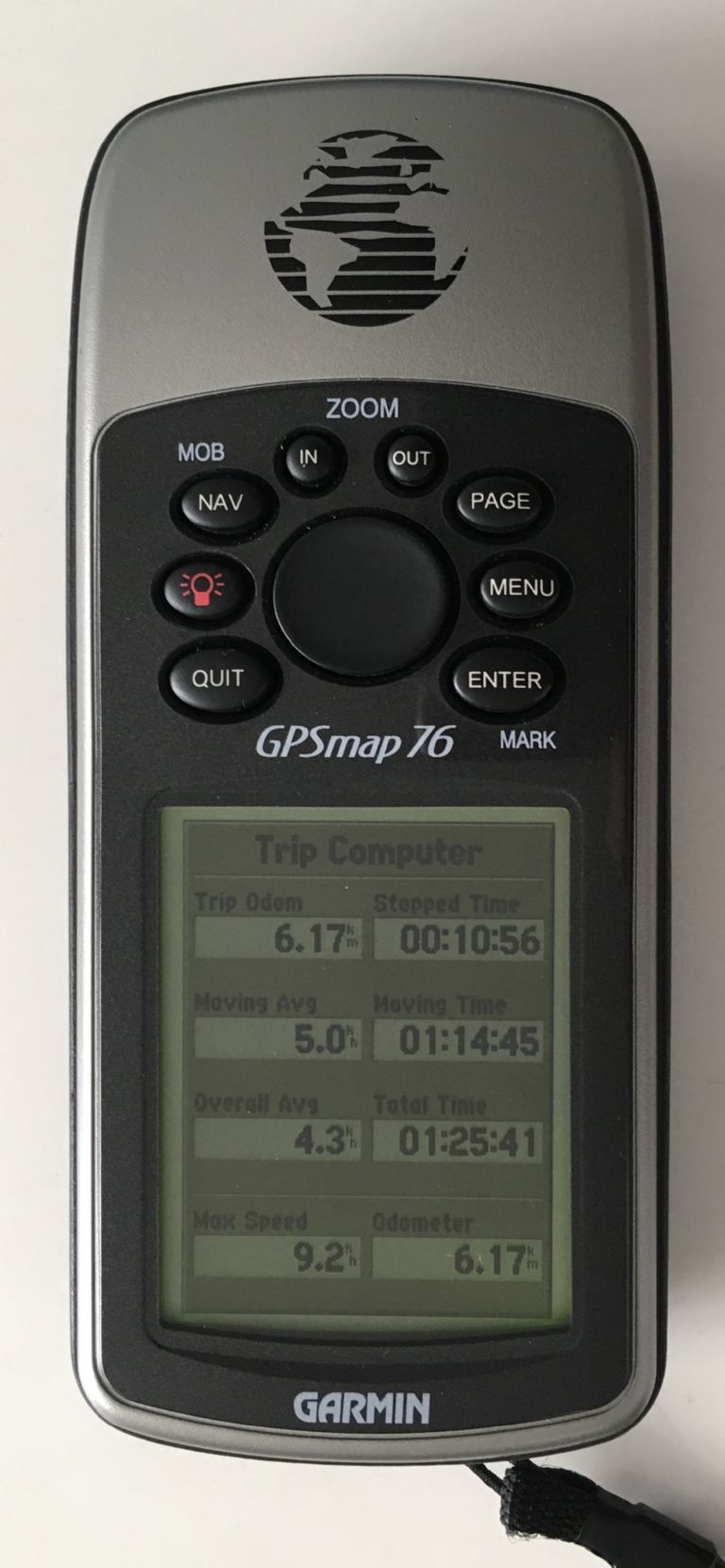
                        This morning, I went for a brisk walk and took the GPS with me [zeroing the trip computer just before I departed]

                        a6ad4076-468c-4977-89a5-3d62ef5cad8b.jpeg

                        .

                        All the numbers look credible … except for Max Speed

                        I would hypothesise that at some point on the walk there was a momentary change in GPS accuracy, or even a brief loss of signal [no, I did not hear any warning beeps] … this would introduce a step change in my apparent location.

                        Not sure how [if at all] this might relate to Dave’s module, static on his window-sill … any thoughts ?

                        MichaelG.

                        #638439
                        John Haine
                        Participant
                          @johnhaine32865

                          As GPS estimates speed from the doppler shift of the received signals, not from differentiating position w.r.t. time, I suspect that the max speed glitch has a different source.

                          #638441
                          SillyOldDuffer
                          Moderator
                            @sillyoldduffer
                            Posted by Michael Gilligan on 20/03/2023 12:47:45:

                            Humour me for a few moments, folks … this could just possibly be relevant to some of Dave’s mysterious ‘jumps’

                            .

                            All the numbers look credible … except for Max Speed

                            I would hypothesise that at some point on the walk there was a momentary change in GPS accuracy, or even a brief loss of signal [no, I did not hear any warning beeps] … this would introduce a step change in my apparent location.

                            Not sure how [if at all] this might relate to Dave’s module, static on his window-sill … any thoughts ?

                            MichaelG.

                            Yes, it's a good hypothesis, but it doesn't explain this particular bug. I'm certain the GPS is innocent because it wasn't turned on! Stepping occurred when the clock was keeping its own time whilst being checked against NTP, not GPS.

                            The log revealed the actual error, which was false bob detection, probably due to my too-simple IR beam sensor. Once in a blue moon the sensor reports the same swing twice. In the rebuild the beam will be tightened with tubes, and if that doesn't work, I'll replace the Arduino module with a much more suitable Sharp sensor.

                            (The Arduino module is a collision detect device. It sprays IR out at 38° and a simple receiver shapes pulses with a comparator. It's crude compared with the Sharp device preferred by John Haine and others, which sends a tight beam and has a Schmitt trigger.)

                            GPS receivers depend on a good clear view of the sky and are upset by reflections and shadows caused by buildings and other ground-level clutter. Portable units have small antenna that don't help. Satellites going in and out of view for any reason can cause stationary receivers to believe they've suddenly changed position, which can show up as a weird max speed. Poor reception can effect second time pulses as well, not that they become inaccurate, but the unit won't emit them unless it's getting good signals from several satellites.

                            The Ublox GPS recommended by Joe Noci performs better than the Adafruit Ultimate GPS I started with. It picks up Russian and European satellites as well as GPS, and is more likely to always have enough satellites in view. The Ublox still doesn't work properly inside my house – the antenna has to be in a window, more sky the better.

                            So GPS is always a suspect, just not guilty this time.

                            Slow progress at this end: got a sort of cold that made me more woolly headed than normal over the weekend. Well enough today to go out and buy the 4" drainpipe needed, but no coconut. The store were only taking cash because their internet was down and my wallet was empty. Rarely spend cash these days, its becoming a bygone…

                            Dave

                            #638471
                            John Haine
                            Participant
                              @johnhaine32865

                              The ubx device has a "survey in" function I think, especially for fixed timing applications. I haven't sussed it out yet but if you leave its antenna in a fixed location for 24 hours at least it can then start deriving accurate time even if there is only one visible satellite.

                              #638482
                              SillyOldDuffer
                              Moderator
                                @sillyoldduffer
                                Posted by John Haine on 20/03/2023 17:47:34:

                                The ubx device has a "survey in" function I think, especially for fixed timing applications. I haven't sussed it out yet but if you leave its antenna in a fixed location for 24 hours at least it can then start deriving accurate time even if there is only one visible satellite.

                                That's good! I'll have to read the manual again – it does lots of interesting things.

                                #638659
                                Michael Gilligan
                                Participant
                                  @michaelgilligan61133

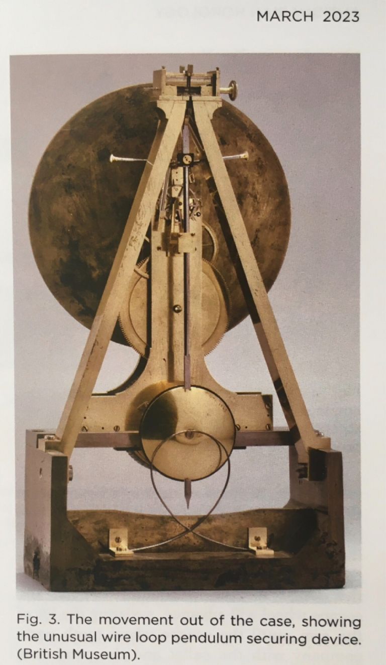
                                  ‘Antiquarian Horology’ arrived in today’s post, and I thought I must share this:

                                  cb205145-3850-45b6-a8db-d3e4042f1119.jpeg

                                  [ treat it as advertising for both theBritish Museum and the Antiquarian Horological Society ]

                                  .

                                  One of two ‘precision clocks’ by William Nicholson [this ‘table regulator’ is dated 1793] featured in a typically excellent article by Jonathan Betts.

                                  That base is cast-iron and there are many interesting features.

                                  MichaelG.

                                  #638850
                                  SillyOldDuffer
                                  Moderator
                                    @sillyoldduffer

                                    Can I have the team's thoughts on how to set a pendulum clock from an accurate time source please?

                                    I've had a go at this on my Experimental Clock this week, and found it harder than expected. It's trivially easy to set my clock within a second of NTP, but doing better is proving tricky.

                                    • I'm aiming for better than 1mS, ideally within 1µS
                                    • There are lots of delays and error sources
                                    • As the pendulum swings don't start at a particular time, the pendulum will be mid swing when the time set message arrives. Somehow the two have to be aligned.

                                    My first attempt goes like this:

                                    • On receipt of a synchronise command, a Raspberry pi enters a loop reading NTP time until the next whole second is reached. There will be a slight overshoot error
                                    • The value of the next whole second is sent to the clock (as the number of seconds and microseconds since 00:00:00 01/01/1970.) Transmission and processing add a not quite constant delay of about 0.0001s,
                                    • The clock sets its seconds counter as ordered, and the microseconds part to zero. If the pendulum was synchronised, the clock would be running somewhat over 0.0001s behind. However, it's not. Instead, because the pendulum will deliver an out of phase tick, special tick is generated
                                    • Although not used for time-keeping, my clock measures the length of each beat with a hardware counter/timer fed continuously with approx 16MHz pulses. As the counter value can be read by the clock at any time, I can calculate the time position of the pendulum with fair accuracy (say ±20µS). So next beat will occur in (period – bobPosition)µS, and this value is counted rather than a full period. Thereafter the clock counts periods as normal.

                                    Works OK, setting the clock to within about 0.025s of NTP time, and I might be able to improve it by compensating for the more or less constant setting delays. But this still won't be good enough! A 5x improvement is needed to hit the 1mS target, and getting with 1µS needs a 5000x improvement.

                                    I'm thinking of adding a second phase, in which the result of setting the clock is compared with NTP, and the difference reported back as a correction. Not thought it through.

                                    This is just one way of doing it, and it feels overcomplicated. Might be better to set the clock by comparing it to NTP at the raspberry without worrying where the bob is, and then sending a few difference corrections until the two align. Or maybe calculate how much it's necessary to temporarily speed up or slow down the period until the clock aligns after 'n' beats.

                                    I think observatories set their their clocks to accurate star time by advancing and locking the hands correctly just before the star passed the transit point. Then a button would be pressed to release the hands at the right moment. Although attempts were made to compensate for human reaction time, I'm not sure how accurate this could be. And my clock doesn't have hands!

                                    Advice, ideas, comments and criticism all welcome.

                                    Thanks,

                                    Dave

                                    #638852
                                    Martin Kyte
                                    Participant
                                      @martinkyte99762

                                      Is it really necessary to synchronise the pendulum with the ref. I may be misunderstanding your requirements though.

                                      Could you use the pendulum sensor to set an offset value in your hardware. You then know the initial phase offset from NTP. “You may have already said that”.

                                      The other way is possibly using the hit and miss synchroniser as per Shortt Synchronome style. Possibly you could use a modified impulse to achieve the same thing.

                                      Just vague thoughts really. Ignore me if you think it’s all a non starter.

                                      regards Martin

                                      #638861
                                      S K
                                      Participant
                                        @sk20060

                                        I'm a bit confused about what you wish to do, including what you mean when you write "clock" or "pendulum clock."

                                        Is your pendulum an accurate seconds one? Or does the "clock" convert its beats to seconds via math? Do you mean a clock circuit driven by the pendulum, meaning that the pendulum is the thing that actually needs to be synchronized? If so, obviously the pendulum will start out of phase and it may take considerable effort over time to coax it into synchronization, if that's even possible.

                                        A possible approach for initial synchronization would be to capture the bob with an electromagnet or some other sort of electro-mechanical trigger, and release it electronically on a beat. One would want to move the electromagnet, etc., out of the way after the release. (I thought about trying that for starting a genuinely-free pendulum's swing at a fixed amplitude for repeatable tests.)

                                        Or do you mean you just wish to synchronize the "clock" (sans pendulum) to reset simultaneously with the external time source without a significant delay, but thereafter be incremented by an out-of-phase (and possibly not even seconds) pendulum? If so, you may need a faster circuit (e.g. an FPGA) or else yes, a repetitive correction in the fashion of a PLL sounds needed.

                                        #638878
                                        SillyOldDuffer
                                        Moderator
                                          @sillyoldduffer
                                          Posted by S K on 23/03/2023 18:24:27:

                                          I'm a bit confused about what you wish to do, including what you mean when you write "clock" or "pendulum clock."

                                          Of course confusing, unless you've read the other threads describing what I'm up to! Life is too short. Briefly a high accuracy pendulum clock, built with modern techniques, designed to run in a vacuum with various novel features. The pendulum period is arbitrary and I only need to know it accurately. A good chunk of the project is about accurately measuring the pendulum, happened to be a noisy 0.823456s in the last iteration.

                                          The oscillator is a pendulum, and the counter/impulser is an Arduino. Together they are a clock, specifically a pendulum clock.

                                          What needs to be synchronised is time, and there are various ways of doing that, including building a fixed seconds pendulum and releasing it to coincide with GPS seconds. Not attempting that, not least because my Mark 1 pendulum took over 15 minutes to settle after a cold start!

                                          So, I have an Arduino counting pulses, and doing the maths needed to increment a counter which can be converted into human time. The counter keeps Unixtime, (ie UTC seconds since 00:00:00.0 1 Jan 1970) which the Arduino can decode into yyyy mm dd hh mm ss.s

                                          The problem is how to get the pendulum clock's counter aligned accurately with NTP (or GPS).

                                          I mentioned the possibility of applying a second phase correction to the complicated method I described and Martin asking 'Is it really necessary to synchronise the pendulum with the ref' crystallised my thinking. As the answer to Martin's question is 'no', I added the code necessary to correct the counter by comparison. Basically, the clock sends it's notion of time to a raspberryPi on every tick. It's a unix timestamp that the pi compares with NTP, and then sends the difference in microseconds back to the clock, which tweaks the counter as required. This looks to be setting my clock to within 20 to 100uS of NTP, hurrah. Difficult to tell exactly how well it's working because my test clock uses the Arduino's ceramic resonator, which drifts quickly and isn't compensated.

                                          I'm rebuilding the pendulum support and vacuum chamber and can't test the software with a real pendulum at the moment.

                                          Dave

                                          #638882
                                          Martin Kyte
                                          Participant
                                            @martinkyte99762
                                            Posted by SillyOldDuffer on 23/03/2023 20:03:06:

                                            Posted by S K on 23/03/2023 18:24:27:

                                            I'm a bit confused about what you wish to do, including what you mean when you write "clock" or "pendulum clock."

                                            Of course confusing, unless you've read the other threads describing what I'm up to! Life is too short. Briefly a high accuracy pendulum clock, built with modern techniques, designed to run in a vacuum with various novel features. The pendulum period is arbitrary and I only need to know it accurately. A good chunk of the project is about accurately measuring the pendulum, happened to be a noisy 0.823456s in the last iteration.

                                            The oscillator is a pendulum, and the counter/impulser is an Arduino. Together they are a clock, specifically a pendulum clock.

                                            What needs to be synchronised is time, and there are various ways of doing that, including building a fixed seconds pendulum and releasing it to coincide with GPS seconds. Not attempting that, not least because my Mark 1 pendulum took over 15 minutes to settle after a cold start!

                                            So, I have an Arduino counting pulses, and doing the maths needed to increment a counter which can be converted into human time. The counter keeps Unixtime, (ie UTC seconds since 00:00:00.0 1 Jan 1970) which the Arduino can decode into yyyy mm dd hh mm ss.s

                                            The problem is how to get the pendulum clock's counter aligned accurately with NTP (or GPS).

                                            I mentioned the possibility of applying a second phase correction to the complicated method I described and Martin asking 'Is it really necessary to synchronise the pendulum with the ref' crystallised my thinking. As the answer to Martin's question is 'no', I added the code necessary to correct the counter by comparison. Basically, the clock sends it's notion of time to a raspberryPi on every tick. It's a unix timestamp that the pi compares with NTP, and then sends the difference in microseconds back to the clock, which tweaks the counter as required. This looks to be setting my clock to within 20 to 100uS of NTP, hurrah. Difficult to tell exactly how well it's working because my test clock uses the Arduino's ceramic resonator, which drifts quickly and isn't compensated.

                                            I'm rebuilding the pendulum support and vacuum chamber and can't test the software with a real pendulum at the moment.

                                            Dave

                                            As a lift once said “Pleased to be of service”

                                            regards Martin

                                            #638884
                                            Michael Gilligan
                                            Participant
                                              @michaelgilligan61133
                                              Posted by SillyOldDuffer on 23/03/2023 17:12:34:

                                              Can I have the team's thoughts on how to set a pendulum clock from an accurate time source please?

                                              […]

                                              I think observatories set their their clocks to accurate star time by advancing and locking the hands correctly just before the star passed the transit point. Then a button would be pressed to release the hands at the right moment. Although attempts were made to compensate for human reaction time, I'm not sure how accurate this could be. And my clock doesn't have hands!

                                              Advice, ideas, comments and criticism all welcome.

                                              Thanks,

                                              Dave

                                              .

                                              I may have touched on this before, Dave … but I think the important underlying difference between a traditional observatory clock and yours is the short-term stability. They are demonstrably very stable, whereas your is like a nervous race-horse.

                                              As you have clearly discovered, It is much easier to check the relatively long-term rate of a conventional clock than the short-term rate of yours … and even checking at the most granular level; a given star only transits once per sidereal day.

                                              If the observatory clock is within [say] one second in ten days, then it is reasonably safe to interpolate that accuracy down to short durations … but what is the comparable ‘reasonably safe’ thing you can do with yours ?

                                              … I don’t know.

                                              MichaelG.

                                              #638894
                                              S K
                                              Participant
                                                @sk20060
                                                The problem is how to get the pendulum clock's counter aligned accurately with NTP (or GPS).

                                                I think part of my confusion is due to the lack of context; the "why" part. Why is it important to you to synchronize the two clocks? Just don't want to be off by up to a second? Do you expect to hold accuracy of <1s for very long?

                                                #638903
                                                SillyOldDuffer
                                                Moderator
                                                  @sillyoldduffer
                                                  Posted by S K on 23/03/2023 21:47:33:

                                                  The problem is how to get the pendulum clock's counter aligned accurately with NTP (or GPS).

                                                  I think part of my confusion is due to the lack of context; the "why" part. Why is it important to you to synchronize the two clocks? Just don't want to be off by up to a second? Do you expect to hold accuracy of <1s for very long?

                                                  I want to set my pendulum clock to UTC from NTP so that my clock starts within 1mS of UTC or better. Not unusual – as I write almost all the clocks round here are set to UTC, more or less inaccurately. Millions of them!

                                                  Yes it has to hold accuracy – my target is to approach the performance of a Shortt-Synchronome which kept time to within 8mS per year.

                                                  My clock steps in units of pendulum period, so it's not continually synchronised with NTP, but on each tick my clock and NTP should be in close agreement.

                                                  Dave

                                                  #638911
                                                  S K
                                                  Participant
                                                    @sk20060

                                                    Seems to me you know how to calculate most of the correction and are just worrying about getting the system delay offset right. You need to find a way to measure that accurately, including the jitter, preferably in hardware. If it's solid, then no problem. Otherwise, it will limit the accuracy. Perhaps running a PID for a while would help dial it in, but you can't leave it running or it will subvert the reason for the pendulum.

                                                    Edited By S K on 24/03/2023 00:38:22

                                                    #638919
                                                    John Haine
                                                    Participant
                                                      @johnhaine32865

                                                      Do you really need to do this? Sounds a bit like trying to synch the OCXO of a gpsdo to utc at switch on. Surely what you need to do is know the period of your pendulum oscillator and its dependence on any environmental variables you want to compensate for. But it's the counter that converts frequency to phase (time) that needs synchronising to ntp surely? One thing you can guarantee is that even if you synchronise the pendulum to an ntp tick it's phase will immediately start to drift away. Unless of course you phase lock it, but that's cheating!

                                                    Viewing 25 posts - 226 through 250 (of 502 total)
                                                    • Please log in to reply to this topic. Registering is free and easy using the links on the menu at the top of this page.

                                                    Advert

                                                    Latest Replies

                                                    Viewing 25 topics - 1 through 25 (of 25 total)
                                                    Viewing 25 topics - 1 through 25 (of 25 total)

                                                    View full reply list.

                                                    Advert

                                                    Newsletter Sign-up