I'm getting very frustrated with my 'controller' for the power drive. I'm writing this hoping for inspiration from the collective brains, or perhaps just to clear my thoughts.
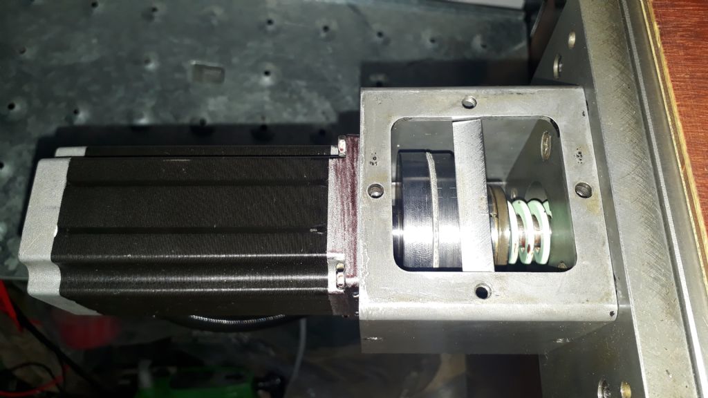
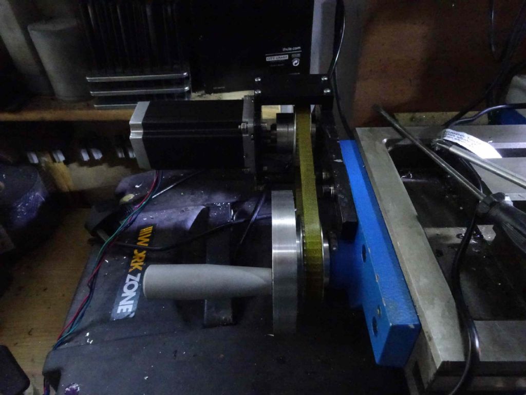
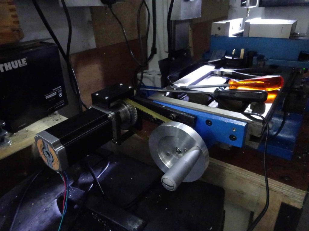
To recap. I've got the hardware and electronics built for the power feed. Using an Arduino nano, I have a program which can drive the power drive, with commands from a PC (other serial terminals are available).
Last I wrote, I'd been working out how to get a nice user interface. What I want to do is to a) have some presents which will cut at various speeds and (optionally) return to the original place. b) allow me to manually control speed, c) generate aforementioned presets and d) have it respect some limit switches in case I muck up my settings.
My other constraints are that I don't want to spend much, I want the user interface to be easy to use. and it shouldn't be too big.
My software skills should be decent (after 40 years man and boy), but are basically limited to microsoft tech.
I was expecting to be able to use one of several android tablets/phones I have, but that proved challenging as none of them can talk to attached devices (SB OTG apparently).. When I found something which would (e.g. my current phone or an el-cheapo), it wasn't obvious how to power the phone whilst it was talking elsewhere.
MY Pis are all early generation and have similar restrictions.I do have an old laptop and an old windows tablet which would do the job, the the laptop is far too big (and XP) and the tablet is too valuable – it's my only portable 'business' device.
What I'm trying at the moment is to use an Arduino mega with an LCD shield.. The software support is very low level and I've spent a bit of time starting to build a windowing system, but I find the touch screen access not terribly reliable – and I don't trust it much.
I've rousted out some rotary encoders I bought a while back and got those working (so I can have input with a rotary switch and output on the LCD). These (really) need to run off some of the interrupt pins on the mega.
Now, the LCD module sits on top of and covers nearly the whole of the top of the mega, using most of the interrupt pins, and leaving very little space to connect to the 3 unused interrupt pins (19, 20, 21). I would have to solder to the board. Which, of course is doable.
So the thing is, every stop forward I take results in two steps back – or so it seems. I can't help but feel that I'm going about this the wrong way – that there's an easier or more obvious way to do it. If pressed, I would confess I'm a little tempted to spend a little more to make my life a little easier – the bits and bobs for prototyping are adding up as a start and discard various approaches.
So I throw myself on your mercy! Any ideas for how to make this a little easier would be most welcome!
Iain
Iain Downs.


