Postman Cometh Part 2

Advert

Postman Cometh Part 2

Home Forums Work In Progress and completed items Postman Cometh Part 2

Viewing 25 posts - 26 through 50 (of 111 total)
  • Author
    Posts
  • #202863
    JasonB
    Moderator
      @jasonb

      Sounds like you need to get yourself an edge finder or a centre finder/sticky pin to pick up the joint

      J

      PS have you sorted out your DRO problem yet?

      Advert
      #202864
      Nick_G
      Participant
        @nick_g
        Posted by JasonB on 01/09/2015 19:23:20:

        Sounds like you need to get yourself an edge finder or a centre finder/sticky pin to pick up the joint

        J


        PS have you sorted out your DRO problem yet?

        .

        My thoughts are that if I use the 12mm PGB that I could also check the vertical alignment of both bearings is good. I don't think my edge finders are long enough to do that with the lower mounted one. Suppose I could use the laser one.

        Yes, DRO problem sorted. That was down to the idiot that installed it not doing a finished job. – Now I wonder who that was. blushblush i.e. the sensor to magnetic scale was not tightened. Ooooops.! surprise

        Nick laugh

        Edited By Nick_G on 01/09/2015 19:34:24

        #202865
        JasonB
        Moderator
          @jasonb

          If you don't have a decent angle plate to mount the casting to then thats probably your best bet of getting the two bearings vertical.

          J

          #202868
          Gas_mantle.
          Participant
            @gas_mantle

            Nice work Nick, I'll look forward to following this thread

            Peter.

            #202930
            Nick_G
            Participant
              @nick_g

              .

              Thank you Peter.

              Work on the bearings has had to take a break for a couple of days. This is due to me being a numptie and not being in possession of a 4BA tap to hold the caps down. So I hope Messers Chronos dispatch the ordered one pronto.

              Nick

              #202967
              mechman48
              Participant
                @mechman48

                M3.5 / M4 would've been the nearest equivalent taps if you were stuck… ?

                thread conversion.jpg

                George.

                #202970
                JasonB
                Moderator
                  @jasonb

                  Probably best to stick with 4BA then you can use the supplied nuts & studs, Nice chart, where have I seen that beforewink 2

                  #202981
                  mechman48
                  Participant
                    @mechman48

                    Hmmm let me think … thinking … gadzooks sir twer it not yours… dont know

                    #202994
                    Nick_G
                    Participant
                      @nick_g

                      .

                      Cheers mechman,

                      But as Jason says I have the studs and I have ordered the HSS taps now.

                      I also really need to replace the existing BA taps I have with HSS ones also. I was very lucky I did not snap the cheep carbon steel ones I bought when building the James Coombes off in castings a couple of times.

                      Nick

                      #203460
                      Nick_G
                      Participant
                        @nick_g

                        .

                        I have been waiting for some tools to be delivered. (still not arrived today sad)

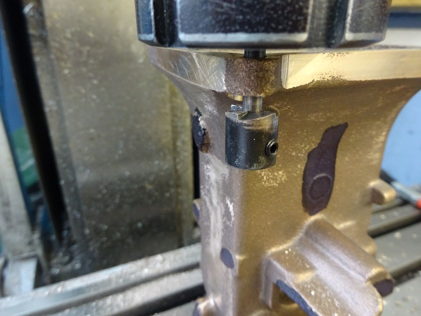
                        So I spent a bit of time over the weekend making a few tools that I will need. I need at some point to drill and face off the standard. This is quite close to other parts of the casting so I would not be able to do it with standard bits of kit. I therefore turned some scrap drilled and reamed the ends to accept such. These were locktited in as they will not be required to be a long lasting service item.

                        The milling bit and drill were held in the tailstock to ensure they went in reasonably straight.

                        This is what they are needed for. :-

                        Also made some T nuts to take some M8 fixings that will be required later. (the ones I already have take M10)

                        The fly wheel is 5in dia (or hopefully will be wink) In order to mount it on the faceplate I would have to drill extra tapped holes into the hub of the D1-3 section. It's not the best of quality faceplates anyway and I am aware that before too long and many projects it would end up looking like the backstop wall after a Mafia firing squad had been active. So on the recommendation of another member I purchased a 20mm thick piece of aluminium. This I will drill and tap onto the plate. (and hopefully stiffen it up a bit) I can then drill and tap fixing holes when ever and where ever I want in the best position for many years to come. Well I hope for many years anyway the price of the damn stuff. sadlaugh

                        Nick

                        #203462
                        JasonB
                        Moderator
                          @jasonb

                          You may find that milling cutter gets a bit lively when you try to use it that far out of the chuck, what you really need to make is a reverse spot facer, easily filed up from a bit of Silver steel, hardened and then clamped onto your drill bit.

                          Can you not use the 4-jaw to hold the flywheel by the inside of the rim? You can usually fit a six spoke in OK

                          #203511
                          Nick_G
                          Participant
                            @nick_g

                            .

                            Hi Jason,

                            That is an inovative way of doing it by reversing the casting. I would never have thought of that. I have though done it before I posted that image and your response.

                            I was mindful of possible chatter but I just had to spot face not cut into a fillet of the casting as you have done. It went OK, but if I had material at an angle to remove I would I think have had problems. Your method is going into filing cabinet in my bonce for future use though.

                            I did consider the 4 jaw for the fly wheel as you suggest, but I think I will be more confident with the faceplate method.

                            Thanks, Nick

                            #203514
                            JasonB
                            Moderator
                              @jasonb

                              Same cutter can be used the right way round fixed to an extended drill or bit of rod so you have a spigot that locates in the hole much like an off the shelf counterbore.

                              I'd also slip a bit of MDF or ply between your ali plate and the flywheel, that way you can machine right across the rim without scoring that nice shiny new plate

                              Edited By JasonB on 08/09/2015 07:47:41

                              #209967
                              Nick_G
                              Participant
                                @nick_g

                                .

                                Hello again folks. smiley

                                It's been a while since I did any work on the No.4. Hopefully I can now get back into the swing of it after my little interlude of making some parts for my mates motorbike turbo conversion. Work has also got in the way of things amongst other distractions.

                                I don't know how others drop straight back into a project. But I find it takes me a few sessions to remember where I was and my plan of attack.

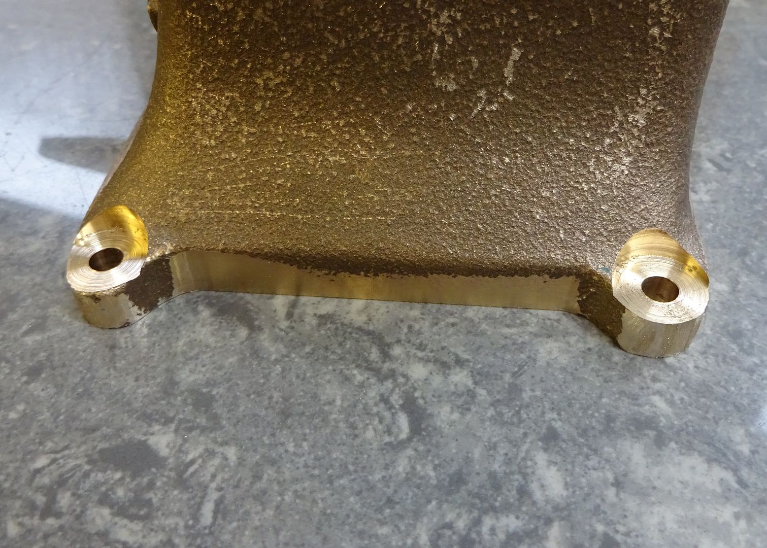
                                Anyway. Decided to finish the main bearings. So they were mounted onto the milling table and drilled out in stages.

                                I did ream to final size but forgot to photograph.

                                Then onto machining the flywheel. I decided to use the faceplate method.

                                I drilled and tapped some holes to fix the flywheel and mounted it with some ali spacers behind.

                                There was an inconsiderate blow hole that reared it's ugly head while facing one of the sides. sad So I had to machine a bit more off than I would have liked. There is still a little bit visible though Grrrrrrr.! But I suppose I can live with that.

                                Resharpened the tool for the final cuts and while it was in the lathe gave it a polish that if had been witnesses by the safety Nazi's would have caused outrage. wink

                                Flipped it over and skimmed and polished the other side face.

                                In the morning I will decide what part I shall puzzle with next.

                                Cheerio, Nick

                                #210144
                                Nick_G
                                Participant
                                  @nick_g

                                  .

                                  Con rod time I think.

                                  I have made a sort of split collet out of aluminium so that I can 'hopefully' hold the rod for the rest of the machining jobs. Any other ways of doing such would of course be welcome. smiley

                                  Nick

                                  #210695
                                  Nick_G
                                  Participant
                                    @nick_g

                                    .

                                    The bearing was sliced with a slitting saw and then faced each side.

                                    It was then fastened back together with solder and machined into thus :-

                                    Another blast of heat to separate the halves again.

                                    Which just leaves a tad of final dressing and a polish.

                                    Nick

                                    #211111
                                    Nick_G
                                    Participant
                                      @nick_g

                                      .

                                      Onto the crankshaft.

                                      This is the supplied casting.

                                      However.! I propose to alter the design slightly as I hope for this engine to actually do some work.

                                      1) Beef the diameter up slightly.

                                      2) Add additional extra outboard bearing making 3 in total on a pedistal (similar in style to the James Coombes and Victoria but slightly bigger) as I feel this will reduce 'whip' on the shaft and provide extra lateral support upon it at the point of the pulley.

                                      3) Increase the length of the shaft to facilitate the extra bearing.

                                      4) Make the webb of the crankshaft so that it has counterweights for hopefully smoother running. (and look 'prettier' wink . )

                                      Avante' :-

                                      Nick


                                      Edited By Nick_G on 08/11/2015 12:38:09

                                      #212526
                                      Nick_G
                                      Participant
                                        @nick_g

                                        .

                                        Next onto the parts that will make the crank web.

                                        I turned some bar down to 2 1/4" and faced it off. I would really have liked to have used the flange jaws in the chuck. But I would not have been able to then get the parting tool in.

                                        Formed a recess and drilled and reamed the center out.

                                        Parted off a bit on the fat size to allow me to reverse in the chuck and make an accurate width.

                                        Obviously 2 need to be made.

                                        I can now split the size by 1/2 ( plus a smidgin ) to give me the final width for each side of the web.

                                        I now need a hole for the big end and to carve out chunks from each side to form the counterweight. The look of each I am yet to decide upon. Think it may be best to temp bond the 2 together when making the holes for the big end.??

                                        Also undecided if to bond and pin the sections with 638 or to silver solder. ??

                                        Nick

                                        Edited By Nick_G on 15/11/2015 21:51:05

                                        #212536
                                        mal webber
                                        Participant
                                          @malwebber91786

                                          Hi Nick nice work, your builds are very interesting to follow thanks

                                          Mal.

                                          #212552
                                          JasonB
                                          Moderator
                                            @jasonb
                                            Posted by Nick_G on 15/11/2015 21:49:48:

                                            . Think it may be best to temp bond the 2 together when making the holes for the big end.??

                                            Ideally the hole could have been done while you had one lump of metal, If your DRO is now working and you can accurately locate centre then no real reason to do them as one, if you are not sure of being able to set them up for equal offset then stick together. Solder construction for me.

                                            Looking good, smashing, super work, etc now you should not be feeling depressed.wink 2

                                            #212559
                                            Nick_G
                                            Participant
                                              @nick_g
                                              Posted by JasonB on 16/11/2015 07:29:03:

                                              Looking good, smashing, super work, etc now you should not be feeling depressed.wink 2

                                              .

                                              lol laugh. So when do you want Belmarsh 'Belinda' to call. surprisedevilwink

                                              Nick

                                              #213489
                                              Nick_G
                                              Participant
                                                @nick_g

                                                .

                                                Work on the webs continues.

                                                Deciding which back rake angle to go for. – On the advice of Jason I went for 30 degrees.

                                                Getting there now. smiley

                                                Then a blip of heat to break the loctite bond.

                                                So it will soon be time for me to have a go at silver soldering for the first time. If it goes pear shaped at least I can sniff the tipex. surprisewink

                                                Nick

                                                #213495
                                                JasonB
                                                Moderator
                                                  @jasonb

                                                  What flux are you using Nick? the HT5 or Tenacity No5 is better for big lumps as it stays lively for longer.

                                                  J


                                                  PS did you have a problem drilling out those holes? wink 2

                                                  Edited By JasonB on 21/11/2015 17:12:09

                                                  #213554
                                                  Nick_G
                                                  Participant
                                                    @nick_g

                                                    .

                                                    Morning Jason. smiley

                                                    Thanks for the advice. I shall order some Tenacity No.5 as you suggest. With this being the first silver soldering I have done I suppose I will not have the 'feel' of it totally. So a flux that stays in the zone longer will be of a good help.

                                                    The holes.? – I presume you mean because they do not look smooth in the bore.? They are. It's just that they have crud in them from dressing the rest of the webs.

                                                    I have had a mail from another member asking how I got rid of the tool machining marks. – I used a fine file, emery paper and a Dremil with the following abrasive in. :- **LINK**

                                                    Nick

                                                    #213571
                                                    JasonB
                                                    Moderator
                                                      @jasonb
                                                      Posted by Nick_G on 22/11/2015 09:09:02:

                                                      The holes.? – I presume you mean because they do not look smooth in the bore.? They are. It's just that they have crud in them from dressing the rest of the webs.

                                                      No, I saw a photo you uploadedcrook

                                                    Viewing 25 posts - 26 through 50 (of 111 total)
                                                    • Please log in to reply to this topic. Registering is free and easy using the links on the menu at the top of this page.

                                                    Advert

                                                    Latest Replies

                                                    Viewing 25 topics - 1 through 25 (of 25 total)
                                                    Viewing 25 topics - 1 through 25 (of 25 total)

                                                    View full reply list.

                                                    Advert

                                                    Newsletter Sign-up