Much depends on what the supply is for.
Older car battery chargers consist of a fuse, small 50hz step-down transformer (30W maybe), and a rectifier. My oldest charger has a single multi-finned copper oxide rectifier, so the output is DC half-wave pulses. The voltage is too high for electroplating, it's hopeless for electronics, and doesn't light 12v bulbs to full brilliance. Good for rough work only, like charging car batteries. Not ideal for that either, because the owner has to disconnect them before they damage batteries by overcharging them. A later model is much the same except it has a moving iron ammeter, and a silicon bridge rectifier. Much better because the ammeter indicates when the battery is charged, more-or-less!
Modern chargers tend to have a switched-mode power supply and electronics that adjust the charge to suit the battery. Not much good for anything else unless perchance the load looks like a battery, which it might. How clean the DC is depends on the unit – anything between spikes and a steady current.
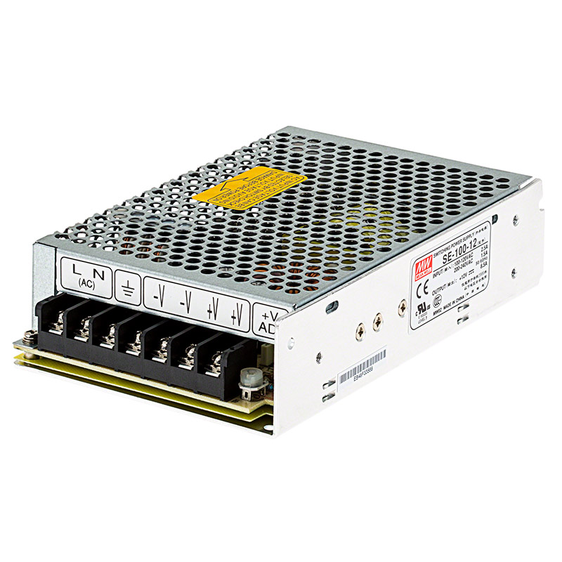
As already said, computer power supplies are probably the best cheap source of clean DC power. However, I prefer cheap readily available LED power-supplies because they come with terminals in a neat rectangular steel box. (They're a nicht-gerfinger poken component, and need to inside a user provided enclosure.)

This type provide well regulated fairly clean DC, and – even though not ideal for the purpose – will power a stepper motor.
For electronic experimentation, it's better to invest in a purpose made bench power supply that provides the voltages needed, with clean metered well-regulated DC and over-current protection. Ideally one with a big 50Hz transformer for low noise, but the switch-mode type are usually satisfactory. Picture is just an example – I don't own one!

I snoop round Aldi/Lidl whenever I get the chance – picked up a few repurposing opportunities, and a pair of just-the-job steel toe-capped trainers.
Dave
Nigel Graham 2.


