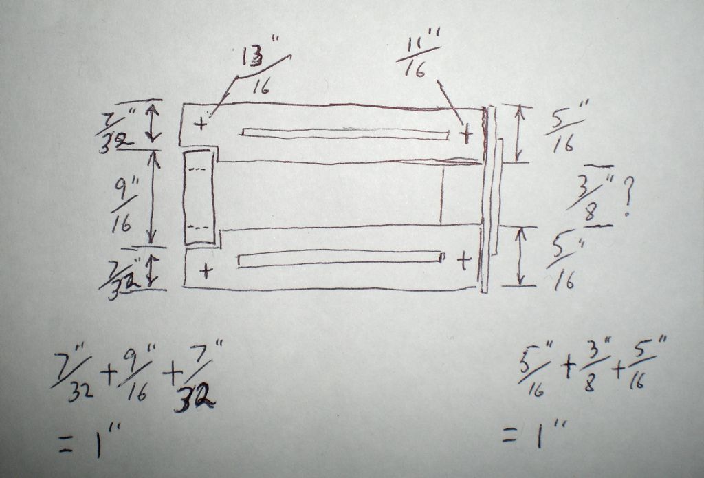
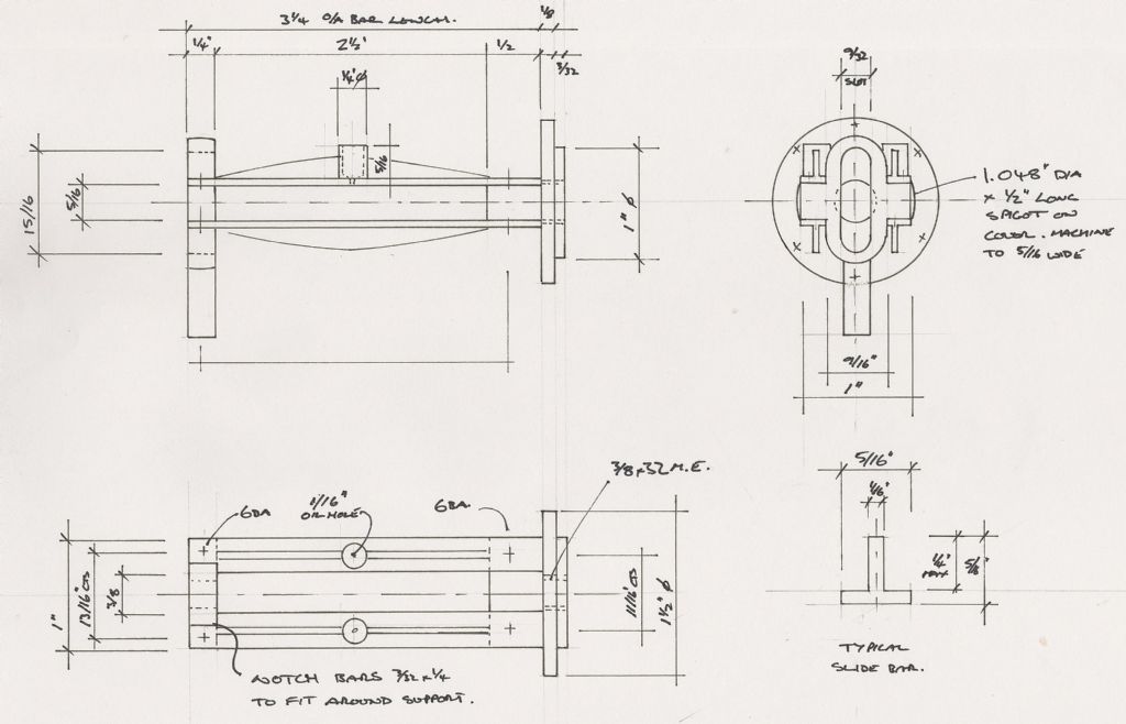
Hi David & Jason, with regards to the slide bar sketch and the question of the 13/16 and 11/16 centres, I believe are being misinterpreted. My understanding of the cross marks these two measurements are referring to are centres of the fixing holes and not of the bars. I do agree that a 3/8 gap makes more sense, in that it makes the 13/16 measurement to be more realistic.
Forgive my rubbish sketch below, but this is how I have interpreted it. At the end where it is shown the 13/16 measurement, there has to be at least 3/32 cut out of the edge of each slide bar to accommodate the loop structure and this would leave 7/32 to accommodate the fixings. If the fixings were to be put in the middle of these 7/32 portions, you would end up with 25/32 centers for the fixings. By adding 1/32 to 25/32 you would arrive at 13/16, which would be a more sensible figure to work to and will give a little more clearance between the loop structure and the fixings.
Nick thats just about the same as the sketch I did back on page 2 or 3. Great minds think alike
Several of Tony's replys specifically say "bars at 11/16" cts" so its not just teh screw holes nearest the cylinder that are at this spacing. I'm going to show a few of the other parts assembled to the bars and this will show when compared to a photo of the engine that the 1" overall width is the most likely correct, off to work now so will do it tonight.
Looking at the next part of the portable, it looks like there are many more errors.
The question is, do I drop the whole series or wait for Tony Webster to correct everything?
It will help me to decide if I know how many people have actually started to build this engine.
Please let me know if you have started this engine ASAP.
Its a shame if it comes to that, maybe ask in the mag as well just incase there are builders who don't visit the website. I know we did have a set of finished wheels posted by one member but they have gone a bit quiet lately.
I'm happy to look over any drawings in advance if it helps. Or even resurect it using the boiler and wheels that we have at the moment and rehash what you have of Tonys drawings so far if there is any demand. As I have said its has the potential to be a good model and the next step from stationary engines upto traction engines.
I have not started to build this model but have been interested in the series and it would be something i would try in the future. If you do scrap the series could you them publish the complete set of drawings so anyone who wants to could try to make the model and check the drawings at the same time.
I had considered doing a significantly scaled down version of this engine and would appreciate eventuallly getting the full set.
The basis of my consideration was to try and scale to a point where I could use a 2" boiler and so fit within the sub-minature AMSBC code (no boiler certificate required). I have not seen a horisontal valve engine at this scale, and suspect it will be somewhat trick to get it looking right.
I made the wheels last year and have been waiting for the whole project the publish before starting the rest, so if you do decide to drop it a full set of the drawings would be good. May be just have a download off the main site.
It would be a shame to pull it. I've just got hold of 12" of 2 5/8" copper boiler tube. I'm considering making a small portablethough i woudln't follow tony's design exactly, more likely roughly following one of the ones John Haining featured over the years.
I'm more interested in Tony's construction methods than his measurements.
It would be a great shame if this project was pulled from the magazine at this stage. Although I have not started to build one I have been following the articles. It is a model that I would consider seriously in the future.