Before fixing the skirt length (see below) check that the lower tubes will fit the lower holes in the firebox tubeplate, clear of the inside of the barrel.
The important dimension, when setting out the tube positions on the firebox tubeplate, is that the top row of tubes should be 11/32in. from the inside of the flange, (or 15/32in. from the outside of the flange if marking out on the other side of the tubeplate). Do not drill the 7/16in.dia holes until the flanges have been made.
When the drawing was redrawn for publication the firebox tubeplate thickness of 3/32in was not transferred.
The 'skirt' i.e. the firebox inner wrapper should be 5/16 inch below the outer wrapper. The foundation ring should be 1/4 inch square all round but you may be only able to obtain 6mm square which will be fine.
The outer door plate (backhead/front plate) and the firebox doorplate should be parallel to each other and vertical.
The firedoor and the water gauge bush should be on the same horizontal centre line and the stays should be equally above and below this centre line and maintain the 11/16in vertical centres. They are offset 1/8in. from the lower ones to place them nearer the centre of the area alongside the firehole.
Get the blowdown bush as low down as you can, i.e. 7/32 inch above the foundation ring.
The drawing says two off regulator bushes, as far as I can see one fits the top of the barrel and the other goes on the backhead.
Q. Should there be any thickening pad inside the boiler to mount the crankshaft bearings? A. The Crankshaft is mounted around the boiler by a strap so no thickening plate should be needed.
Q. Should there be blind bushes to mount the firedoor Hinge
Q. Confirmation of an available thickness for copper in substitution for the 3/32 inch and 1/8 inch thickness shown on drawing. A. Go slightly thicker not thinner.
Q. Will the cylinder stud holes be detailed on the valve chest drawing? A. The positions for the 10 off valve chest stud holes are detailed with the valve chest.
Q. For the cylinder drawing the text says machine the valve face back to lines 1 and 2 but drawing shows it at least 1/32 inch away from them. A. Machine to the line as the text says.
Q. The length of cylinder and protrusion of end faces are not shown on the drawing? A. They can be found in the text.
Q. There is no depth for the steam port slots. A. They must not beak into the cylinder bore.
Q. Width of valve chest given as 3/8 inch? A. This should be 1 3/8 inches.
Q. No length is given for the piston rod. A. I am awaiting the length.
The 1/4in piston rod dia. should be stepped down to 3/16 inch and threaded 3/16 x 40. To save creating a stress point at such a step, taper at 60 degrees inclusive and 'countersink' the piston with a combination centre drill before drilling tapping size for 3/16 x 40.
Q. Crosshead has no thickness given. A. 3/8 inch should be fine.
Q. No depth for piston ring groove. A. Make deep enough to take packing or alternatively use O ring charts to fit an O ring.
Q. No length of 1/4 x 40 thread on piston rod. A. Make to a length to screw into the crosshead as far as the slot, approximately 5/16 inch.
Q. No depth for cut out in crosshead. A. 9/16 inch will be OK to clear little end.
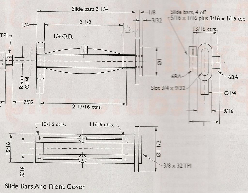
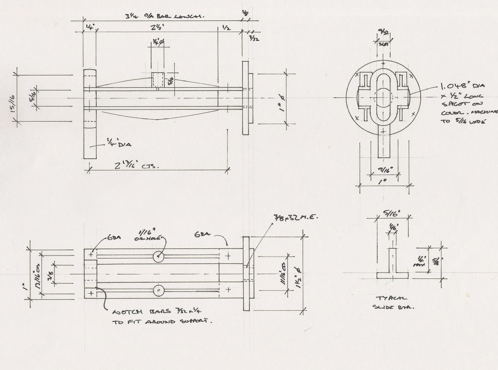
Slide bar drawing
Q. The plan view gives width over the outside of the bars and bracket as 15/16 inch. A. This is correct.
Q. The plan view gives one end of the bars at 13/16 inch centres and the other end at 11/16 inch centres? A. This is correct; you will have to relieve the slide bars at the left-hand end, as drawn, to clear the oval section.
Q. The end elevation gives the bracket as 1 inch wide and the bars project beyond the bracket. A. The bars should not project outside the 1 inch dimension. I think the 1 inch is also related to the 1 inch diameter that enters the cylinder.
Q. The oil cup does not show the hole carried through the slidebar. A. It goes right through the top slidebar.
The valve chest
The blind valve end is shown with a 3/16 x 40 male thread, if you look back at issue 4427 the valve chest that this is meant to screw into is shown with a plain 3/16 inch hole at each end. That is why I said that I hope no one has made the chest as it should obviously have had one end threaded 3/16×40 for the bush to screw into.
While correcting the valve chest it’s worth pointing out that there is no form of gland shown on the rod side either so may be worth sorting that out at the same time.
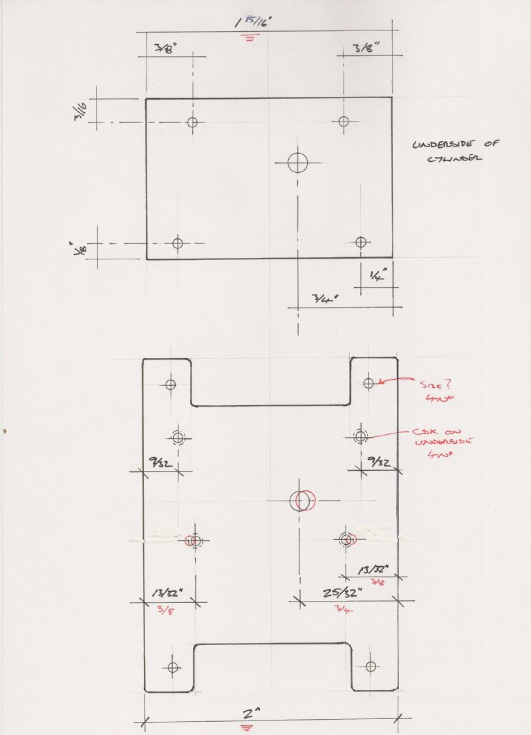
Cylinder saddle.
Q. Is this the actual view of a developed shape of the curved part.
Q. The 1/8in. dimension at the bottom left is wrong, it should probably be ¼ inch.
Q. The two 9/32 inch dimensions on the left seem wrong as the hole will break through the edge, 11/32 inch would be nearer what is right.
I feel this drawing is wrong, the reason being that the position of the 1/4 inch steam feed hole and two of the four mounting holes are dimensioned at 3/4 inch and 3/8 inch in from the edge respectively. They also have the same dimension in from the end of the inverted cylinder plan that was in issue 4426. The problem is that the base of the cylinder is only 1 15/16 inch long but the saddle is 2 inches long so no allowance has been made for the 1/32 inch difference at this end but it has at the other because the holes are shown at 9/32 inch which is the 1/4 inch + 1/32 inch.
continued below
Edited By David Clark 1 on 11/05/2012 19:08:05
Keith.


